
 Open Access Article
 This Open Access Article is licensed under a
 Creative Commons Attribution 3.0 Unported Licence
Li2ZnTi3O8/graphene nanocomposite as a high-performance anode material for lithium-ion batteries†
Song Wanga,
Lijuan Wang *ab,
Zhaohui Meng*b and
Baomin Luob
*ab,
Zhaohui Meng*b and
Baomin Luob
aSchool of Chemistry and Material Science, Liaoning Shihua University, Fushun 113001, Liaoning, China. E-mail: lijuanw123@163.com; Fax: +86-24-56861709; Tel: +86-24-56861711
bCollege of Chemistry and Pharmaceutical Engineering, Nanyang Normal University, Nanyang 473061, Henan, China
First published on 10th September 2018
Abstract
An Li2ZnTi3O8/graphene (LZTO/G) anode is successfully synthesized by a two-step reaction. The results show that LZTO particles can be well dispersed into the graphene conductive network. The conductive structure greatly improves the electrochemical performance of LZTO/G. When cycled for 400 cycles, 76.4% of the capacity for the 2nd cycle is maintained at 1 A g−1. Also, 174.8 and 156.5 mA h g−1 are still delivered at the 100th cycle for 5 and 6 A g−1, respectively. The excellent cyclic performance and the large specific capacities at high current densities are due to the good conductive network of the LZTO active particles, large pore volume, small particle size, low charge-transfer resistance and high lithium diffusion coefficient.
Introduction
Spinel Li2ZnTi3O8 (LZTO) is highly competitive as an anode material for lithium-ion batteries (LIBs) due to its environment-friendly raw materials, good safety and simple synthetic process.1–11 The insertion/deinsertion reaction for Li+ ions in LZTO can be expressed as follows:| Li2ZnTi3O8 + 3Li+ + 3e− ↔ Li5ZnTi3O8 | (1) |
As seen in eqn (1), Ti4+ can be reduced to Ti3+ when discharged to 0 V in LZTO with relatively large theoretical capacity of 227 mA h g−1. However, its electronic conductivity and rate capability need to be greatly improved.
The preparation of conductive carbon coating on nanosized LZTO is considered as an effective approach to improve its electrochemical performance.12–16 The conductive carbon coating can enhance the electronic conductivity of LZTO, and nano-sized particles improve the diffusion of Li+ ions. Recently, graphene (G), an ideal carbon source with high electronic conductivity, has been widely used to modify cathode and anode materials for LIBs to improve their electrochemical performance.17–23 However, to the best of our knowledge, no research on the synthesis of nanosized LZTO/G using G as the conductive carbon has been reported.
In this paper, we report for the first time, the preparation of LZTO/G nanocomposite with excellent high rate capability and cyclic performance. LZTO nanoparticles are enwrapped in a conductive network of G layers. The existence of G greatly improves the electrochemical performance of LZTO.
Experimental
Synthesis of graphene oxide (GO) sheets
GO sheets were prepared via a modified Hummers method24,25 and our previously reported method.26 The synthesis process is shown in the ESI.†Synthesis of Li2ZnTi3O8/graphene (LZTO/G)
The LZTO/G anode was synthesized by the molten-salt method similar to our previous method.15 TiO2 (anatase, A.R.), LiOH·H2O (A.R.), LiNO3 (A.R.) and ZnO (A.R.) were ball-milled for 5 h with Li/Zn/Ti = 2.4![[thin space (1/6-em)]](https://www.rsc.org/images/entities/char_2009.gif) :1:3. The molar ratio of LiOH·H2O to LiNO3 was 0.38:0.62. The mixture was dried at 80 °C for 12 h in air, pre-heated at 250 °C for 3 h and then at 600 °C for 4 h in air, mixed with GO sheets by ultrasonically treating for 2 h, stirred for 24 h using ethanol as the dispersing medium, dried at 80 °C in air and finally sintered at 700 °C for 3 h in N2/H2 (v/v = 93:7). The obtained material was denoted as LZTO/G. For comparison, LZTO was also fabricated by the same method without GO sheets.
:1:3. The molar ratio of LiOH·H2O to LiNO3 was 0.38:0.62. The mixture was dried at 80 °C for 12 h in air, pre-heated at 250 °C for 3 h and then at 600 °C for 4 h in air, mixed with GO sheets by ultrasonically treating for 2 h, stirred for 24 h using ethanol as the dispersing medium, dried at 80 °C in air and finally sintered at 700 °C for 3 h in N2/H2 (v/v = 93:7). The obtained material was denoted as LZTO/G. For comparison, LZTO was also fabricated by the same method without GO sheets.
Physical and electrochemical performance measurements
The related physical and electrochemical performance measurements are shown in the ESI† in detail.Results and discussion
Fig. 1 exhibits a schematic of the two-step reaction for the synthesis of the LZTO/G nanocomposite. In the first step, LZTO is prepared by preheating the precursors of LiOH·H2O, LiNO3, ZnO and TiO2 at 250 °C for 3 h and then at 600 °C for 4 h in air (Fig. S1a and b†). In the second step, the mixture of LZTO and GO is ultrasonicated, stirred and sintered in N2/H2. The LZTO nanoparticles can be completely absorbed on and combined with GO sheets due to the existence of carboxyl, hydroxyl and epoxy groups27 on the surfaces of GO sheets (Fig. S1c†), which can subsequently be converted to G at a high temperature in reductive atmosphere. Then, a conductive G network enwrapping the LZTO particles is formed. The structure is beneficial to the insertion and deinsertion of Li+ ions. In addition, G has outstanding electronic behavior and makes the electronic conductivity of LZTO/G reach 0.3767 S cm−1, which is greatly larger than that of LZTO (7.7 × 10⁻⁶ S cm−1) (Table S1†).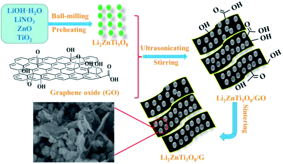 | ||
| Fig. 1 Schematic illustration for the synthesis process of the LZTO/G nanocomposite. | ||
The XRD patterns of GO and G are shown in Fig. S2a.† The (002) reflection peak of GO (2θ = 8.9°) shifts to a higher value (2θ = 26.2°) in G. Based on the Bragg's equation 2dsinθ = nλ, where d is the interlayer spacing, θ is the diffraction angle, n is the diffraction order, and λ is the wavelength of Cu Kα, the interlayer spacings of GO and G are determined as 0.982 and 0.339 nm, respectively. The expansion of d indicates the formation of oxygen-containing groups between the GO layers. The decrease in d verifies the removal of oxygen functional groups in G.
The Raman spectra of GO and G are shown in Fig. S2b.† The spectrum displays two bands at 1357 cm−1 (D band, disorder-induced phonon mode) and 1605 cm−1 (G-band, graphite band) for each sample. The ID/IG intensity ratio indicates the degree of disorder and can be used to confirm the reduction process. The ID/IG ratio values are 0.945 and 0.988 for GO and G, respectively. It can be seen that the value increases after reduction, indicating that oxygen moieties are removed during the reduction process.28
The morphologies of GO and G are characterized by SEM and TEM (Fig. S2c–f†). GO displays typically rippled and crumpled surfaces (Fig. S2c†). G has sheet-like structures (Fig. S2d†). It can be seen from the TEM images (Fig. S2e and f†) that the multilayered GO sheets evolve into single or several layered G after reduction at 700 °C.
The XRD patterns of LZTO and LZTO/G anode materials are depicted in Fig. 2. For each sample, the diffraction peaks can be assigned to the cubic spinel structure of LZTO (JCPDS#44-1037). For the LZTO/G sample, the diffraction peak related to G is detected. The G content in LZTO/G composite is 8.67 wt% (Fig. S3†). XPS and Raman results further confirm that GO is reduced to G. (Fig. S4†). The lattice parameters are listed in Table S2.† Compared with LZTO, LZTO/G has larger lattice parameters, which may originate from the creation of oxygen vacancies due to the incomplete crystallinity of LZTO with the existence of G;29,30 this is suitable for rapid transportation of Li+ ions.29
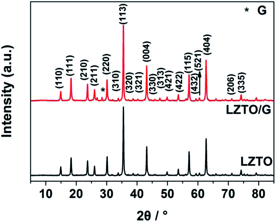 | ||
| Fig. 2 X-ray diffraction patterns of the LZTO and LZTO/G anode materials. | ||
SEM images of the LZTO and LZTO/G anode materials are shown in Fig. 3. Compared with LZTO, the LZTO/G sample has a smaller particle size; it is looser as well as more porous due to the existence of G. The introduction of G greatly enhances the specific surface area and the total pore volume of LZTO (Fig. S5 and Table S3†). The large specific surface area and pore volume are beneficial for fast diffusion of Li+ ions.
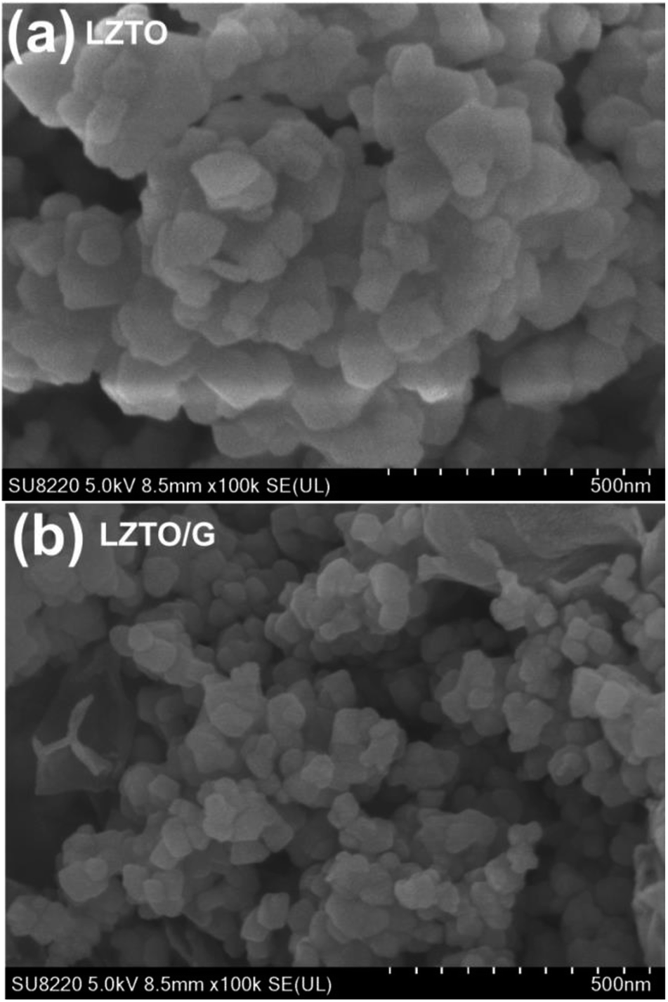 | ||
| Fig. 3 SEM images of (a) LZTO and (b) LZTO/G. | ||
TEM images of LZTO and LZTO/G are provided in Fig. 4. It is clear that there is a thin G layer coating on LZTO particles (Fig. 4b). The energy dispersive spectroscopy (EDS) results (Fig. S6b†) indicate that O, Ti, Zn and C exist in the LZTO/G composite. The elemental mappings (Fig. S6c–f†) suggest that the elements are uniformly dispersed.
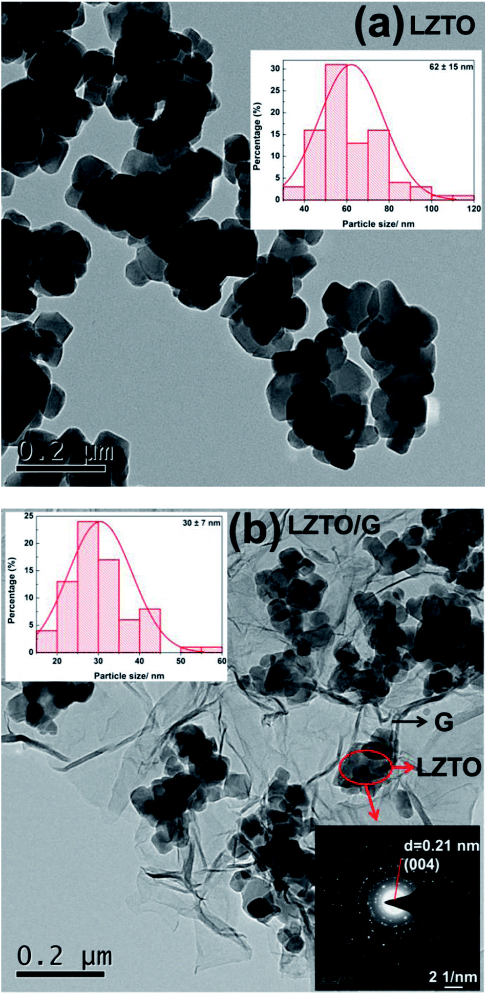 | ||
| Fig. 4 TEM images, histograms of particle size distribution (inset, top) and selected area electron diffraction (SAED) pattern (inset, bottom) of (a) LZTO and (b) LZTO/G. | ||
Compared with LZTO, LZTO/G has a smaller particle size of 30 nm, further verifying that the existence of G can prohibit particle growth. Small particle size benefits the rate capability of LZTO/G. Selected-area electron diffraction (SAED) pattern shows that the LZTO particles are polycrystalline in the LZTO/G composite.
Fig. 5a exhibits the initial charge–discharge curves of LZTO and LZTO/G at 1 A g−1 in the range of 0.02–3.0 V. For each sample, a charge plateau (1.48 V) and a corresponding discharge plateau (0.37 V) are observed, which indicate the typical electrochemical reaction of LZTO;1–11 this is further confirmed by the results of the CV technique (Fig. S7 and Table S4†). Compared with LZTO, LZTO/G has larger specific capacity of 275.0 mA h g−1 (Table 1) due to its larger specific surface area and the existence of G. However, the larger specific surface area of LZTO/G can also result in more side reactions and lower coulombic efficiency of 72.0% (Table 1). After several cycles, the coulombic efficiencies are close to 100% for the two samples, which indicates that large reversible capacities can be obtained (Fig. 5b). The cyclic performances of LZTO and LZTO/G at 1 A g−1 are shown in Fig. 5b. Also, 182.3 and 221.4 mA h g−1 are delivered at the 2nd cycle for LZTO and LZTO/G, respectively. When cycled for 400 cycles, 75.8% and 76.4% of the capacities for the 2nd cycle are maintained. When the current densities increase, LZTO/G still has better electrochemical performance. For instance, at 2 A g−1, 213.9 mA h g−1 is delivered at the 2nd cycle with the capacity retention of 72.3% at the 300th cycle (Fig. 5c and Table 2); at 3 A g−1, 150.7 mA h g−1 is obtained with the capacity retention of 72.7% at the 300th cycle (corresponding to that at the 2nd cycle) (Fig. 5d and Table 2). The large capacity or good cyclic performance of LZTO/G exceeds many previously reported values (Table S5†).
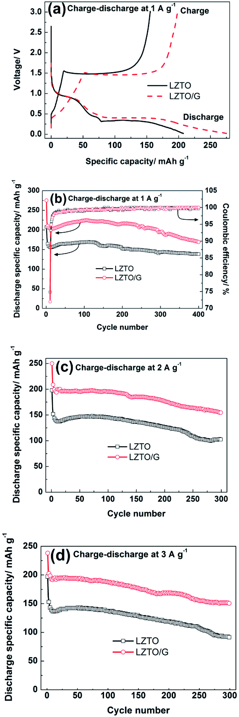 | ||
| Fig. 5 (a) Initial charge–discharge curves and (b) cyclic performances (inset, the corresponding columbic efficiency) of LZTO and LZTO/G at 1 A g−1 from 0.02 to 3.0 V (vs. Li/Li+); cyclic performances of LZTO and LZTO/G at (c) 2 A g−1 and (d) 3 A g−1 from 0.02 to 3.0 V (vs. Li/Li+). | ||
| Samples | Specific capacity at the 1st cycle (mA h g−1) | Coulombic efficiency | Specific capacity at the 400th cycle (mA h g−1) | Capacity retention for the 2nd cycle |
|---|---|---|---|---|
| LZTO | 207.5 | 74.9% | 182.3 | 75.8% |
| LZTO/G | 275.0 | 72.0% | 221.4 | 76.4% |
| Current density (A g−1) | LZTO, specific capacity at the 2nd cycle (mA h g−1) | Capacity retention for the 2nd cycle | LZTO/G, specific capacity at the 2nd cycle (mA h g−1) | Capacity retention for the 2nd cycle |
|---|---|---|---|---|
| 2 | 162.4 | 63.1% | 213.9 | 72.3% |
| 3 | 91.5 | 56.4% | 150.7 | 72.7% |
In addition, the electrode kinetics of LZTO and LZTO/G were investigated. Compared with LZTO, LZTO/G exhibited smaller charge transfer resistance of 187.6 Ω and higher lithium-ion diffusion coefficient of 3.65 × 10⁻¹⁵ cm2 s−1 (Fig. S8 and Table S6†), which indicated good rate capability of LZTO/G. Also, 174.8 and 156.5 mA h g−1 were still delivered at the 100th cycle for 5 and 6 A g−1, respectively (Fig. 6). The capacities were larger and the cyclic performance was better than many previously reported results (Table S5†).
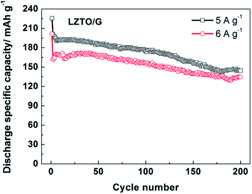 | ||
| Fig. 6 Cyclic performance of the LZTO/G electrode at high current densities of 5 and 6 A g−1 in the range of 0.02–3.0 V. | ||
To further clarify different electrochemical behaviors of LZTO and LZTO/G, the two electrodes were extracted from the cells after cycling for 200 cycles at 1 A g−1. The surface of the LZTO electrode was severely damaged with clear cracks (Fig. S9a†), which could worsen its cyclic performance. However, the active material layer stayed integrated for the LZTO/G electrode (Fig. S9b†), which can form a good conductive layer. Moreover, compared with that observed for the LZTO electrode, there was better adhesion between the LZTO/G active material coating and the Cu current collector (Fig. S9c and d†), which could help maintain a whole conductive network.
Conclusions
An LZTO/G nanocomposite has been successfully synthesized by a two-step reaction. LZTO particles can be well dispersed into the G conductive network. The structure is beneficial for the insertion and deinsertion of Li+ ions. G having outstanding electronic behavior can improve the electronic conductivity of LZTO/G, which exhibits large specific capacities and good cycling performance at high current densities. This method is simple as well as efficient and can be extended to the preparation of other electrode materials.Conflicts of interest
There are no conflicts to declare.Acknowledgements
We acknowledge financial support from the Henan Joint Funds of the National Natural Science Foundation of China (U1504532 and U1504531) and the Henan Province Project Education Fund (17A150042).Notes and references
- C. Chen, C. Ai, X. Liu and Y. Wu, Electrochim. Acta, 2017, 227, 285 CrossRef.
- Y. Ren, P. Lu, X. Huang, J. Ding and H. Wang, RSC Adv., 2016, 6, 49298 RSC.
- W. Chen, H. Liang, W. Ren, L. Shao, J. Shu and Z. Wang, J. Alloys Compd., 2014, 611, 65 CrossRef.
- Z. Hong, X. Zheng, X. Ding, L. Jiang, M. Wei and K. Wei, Energy Environ. Sci., 2011, 4, 1886 RSC.
- F. Qie and Z. Tang, Mater. Express, 2014, 4, 221 CrossRef.
- H. Yang, X. Wang, Y. Qi, N. Lun, Y. Cao and Y. Bai, ACS Sustainable Chem. Eng., 2017, 5, 6099 CrossRef.
- H. Tang, Q. Weng and Z. Tang, Electrochim. Acta, 2015, 151, 27 CrossRef.
- H. Li, Z. Li, Y. Cui, C. Ma and Z. Tang, New J. Chem., 2017, 41, 975 RSC.
- L. Wang, L. Wu, Z. Li, G. Lei, Q. Xiao and P. Zhang, Electrochim. Acta, 2011, 56, 5343 CrossRef.
- B. Chen, C. Du, Y. Zhang, R. Sun, L. Zhou and L. Wang, Electrochim. Acta, 2015, 159, 102 CrossRef.
- T. Yi, J. Wu, J. Yuan, Y. Zhu and P. Wang, ACS Sustainable Chem. Eng., 2015, 3, 3062 CrossRef.
- C. Chen, C. Ai, Y. He, S. Yang and Y. Wu, J. Alloys Compd., 2017, 705, 438 CrossRef.
- Y. Xu, Z. Hong, L. Xia, J. Yang and M. Wei, Electrochim. Acta, 2013, 88, 74 CrossRef.
- H. Tang and Z. Tang, J. Alloys Compd., 2014, 613, 267 CrossRef.
- L. Wang, B. Chen, Z. Meng, B. Luo, X. Wang and Y. Zhao, Electrochim. Acta, 2016, 188, 135 CrossRef.
- Z. Meng, L. Wang, X. Li, G. Zhang and H. Li, Int. J. Hydrogen Energy, 2017, 42, 2177 CrossRef.
- X. Tian, Y. Zhou, X. Tu, Z. Zhang and G. Du, J. Power Sources, 2017, 340, 40 CrossRef.
- B. Chen, Y. Meng, F. He, E. Liu, C. Shi, C. He, L. Ma, Q. Li, J. Li and N. Zhao, Nano Energy, 2017, 41, 154 CrossRef.
- B. Luo and L. Zhi, Energy Environ. Sci., 2015, 8, 456 RSC.
- P. Xiong, J. Zhu, L. Zhang and X. Wang, Nanoscale Horiz., 2016, 1, 340 RSC.
- L. Shi and T. Zhao, J. Mater. Chem. A, 2017, 5, 3735 RSC.
- Y. Zhong, M. Yang, X. Zhou and Z. Zhou, Mater. Horiz., 2015, 2, 553 RSC.
- M. Zhen, S. Guo, G. Gao, Z. Zhou and L. Liu, Chem. Commun., 2015, 51, 507 RSC.
- Y. Xu, H. Bai, G. Lu, C. Li and G. Shi, J. Am. Chem. Soc., 2008, 130, 5856 CrossRef PubMed.
- N. Kovtyukhova, P. Ollivier, B. Martin, T. Mallouk, S. Chizhik, E. Buzaneva and A. Gorchinskiy, Chem. Mater., 1999, 11, 771 CrossRef.
- D. Pan, S. Wang, B. Zhao, M. Wu, H. Zhang, Y. Wang and Z. Jiao, Chem. Mater., 2009, 21, 3136 CrossRef.
- H. Wang, L. Cui, Y. Yang, H. Casalongue, J. Robinson, Y. Liang, Y. Cui and H. Dai, J. Am. Chem. Soc., 2010, 132, 13978 CrossRef PubMed; X. Zhu, Y. Liu, L. Geng and L. Chen, J. Power Sources, 2008, 184, 578 CrossRef.
- S. Stankovich, D. Dikin, R. Piner, K. Kohlhaas, A. Kleinhammes, Y. Jia, Y. Wu, S. Nguyen and R. Ruoff, Carbon, 2007, 45, 1558 CrossRef.
- X. Zhou, Y. Liu and Y. Guo, Electrochim. Acta, 2009, 54, 2253 CrossRef.
- T. Liu, H. Tang, L. Zan and Z. Tang, J. Electroanal. Chem., 2016, 771, 10 CrossRef.
Footnote |
| † Electronic supplementary information (ESI) available. See DOI: 10.1039/c8ra05893h |
| This journal is © The Royal Society of Chemistry 2018 |