 Open Access Article
Surface characterization and degradation behavior of polyimide films induced by coupling irradiation treatment
Shan-Shan Donga,
Wen-Zhu Shao *a,
Li Yanga,
Hui-Jian Yeb and
Liang Zhena
aSchool of Materials Science and Engineering, Harbin Institute of Technology, Harbin, 150001, China. E-mail: wzshao@hit.edu.cn; Fax: +86-451-86413921; Tel: +86-451-86412133
bInstitute of Polymer Materials and Engineering, College of Materials Science and Engineering, Zhejiang University of Technology, Hangzhou, 310001, China
First published on 6th August 2018
Abstract
The degradation behavior of polyimide in extreme environments, especially under coupling treatment, directly determines the service life of several key components in spacecraft. In this research, the combined effect of a high energy electron beam (1.2 MeV), heavy tensile stress (50 MPa) and constant high temperature (150 °C) was taken into account to study the surface modification and degradation behavior of polyimide films. By analyzing surface morphology, microstructural evolution and mechanical behavior of polyimide films after coupling treatment, the results indicated that the coupling treatment led to severe breakage of chemical bonds and decrease of surface quality. Meanwhile, new chemical bonds of C–C, CH2–O and C![[triple bond, length as m-dash]](https://www.rsc.org/images/entities/char_e002.gif) N formed after coupling treatment. Additionally, a high dose of electron beam during coupling experiments contributed to the formation of an oxide layer, surface defects and even volatile gases in the outer layer of the polyimide film. This was attributed to the significant scissioning of molecular chains in polyimide films and corresponding chemical reactions between free radicals and oxygen in air. Consequently, the irradiation-load-heating coupling treatment led to a remarkable drop in viscoelastic properties and mechanical performance of polyimide films.
N formed after coupling treatment. Additionally, a high dose of electron beam during coupling experiments contributed to the formation of an oxide layer, surface defects and even volatile gases in the outer layer of the polyimide film. This was attributed to the significant scissioning of molecular chains in polyimide films and corresponding chemical reactions between free radicals and oxygen in air. Consequently, the irradiation-load-heating coupling treatment led to a remarkable drop in viscoelastic properties and mechanical performance of polyimide films.
1. Introduction
In recent decades, polyimide has been widely applied as structural materials under extreme environments, such as in spacestations and nuclear installations.1–3 The applications include shielding materials, thermal blankets, solar sails and arrays that depend on its reliable thermal stability and performance.4–6 When exposed to damaging environments with effects of protons, electrons, solar ultraviolet radiation or thermal cycling, the microstructure and properties of polyimide will strongly be affected and tends to degrade gradually, which will lead to reducing the reliability of components in spacecraft or even mission failure.7–13 Consequently, it is important to figure out the degradation behavior and mechanism of polyimide under these threatening environments.There have been thorough investigations of space's environmental effects on polyimide degradation behaviors and performances. It was believed that the energized particles would lead to variation in chemical structure through scissioning and crosslinking among polyimide molecular chains.13 In this process, the original chemical bonds in polyimide tended to be broken and new chemical bonds formed simultaneously. In the meantime, the free radicals might be induced during irradiation and react with oxygen in polyimide, which would facilitate to the formation of oxide layer in polyimide surface or even volatile gases.14–16 These chemical reactions and corresponding microstructural transformations during irradiation would lead to significant changes in performance of polyimide, such as mechanical properties, insulating properties, optical performances, surface quality and thermal stability.17–19 Investigations indicated that tensile strength and elongation of polyimide dropped significantly after high dose of irradiation.20 It was reported that heavy ions with high energy could even lead to progressive carbonization and graphitization of polyimide, which dramatically dropped the sheet resistance of polyimide films with increasing ion fluence.21 Researchers also believed that the increase of surface roughness and optical degradation were mainly caused by the scissioning and then carbonization of the molecular chains in the polyimide.17,22 Therefore, the polyimide samples tend to degrade after different kinds of irradiation and then result in reduced reliability of space components or even huge economic loss.
When polyimide components are placed in space, the irradiation by high energy particles is not the only factor to be considered with regard to degradation behavior of polyimide. For instance, the solar panels and sail are not only irradiated by high energy particles, but also in a state of tensile stress, which might result in creep and plastic deformation. Hence, the coupling effect by combination of tensile stress and irradiation could be unneglectable when analyzing degradation behavior of polyimide. It was reported that the low energy (0.2 MeV) electron beam and tensile stress (<7 MPa) coupling treatment had little effect on the mechanical properties of polyimide.11,20 When heavy load over 40 MPa was applied, however, the tensile stress might initiate rapid degradation in irradiated polyimide, which mainly caused by the acceleration of molecular chains' scissioning in polyimide films.8,23 Our previous research also confirms that irradiation-load coupling treatment will lead to more severe breakage of chemical bonds, surface erosion and drop of mechanical properties, comparing with the only irradiated polyimide samples. Therefore, the stress state has effect on the microstructure, surface morphology and mechanical performance of polyimide under irradiation environment, which has to be considered in process of failure analysis tests.
Additionally, orbital extreme temperature and thermal cycling might lead to thermal degradation of polymer materials, which are also potential causes of fractures. According to the mission profile and simulated results, the surface temperature of solar arrays in space varied from −150 °C to more than 120 °C.24,25 In spite of the excellent thermal stability of polyimide, the long-term high temperature would bring about thermal stress which caused unrecoverable damage microstructure and potential dangers.26–28 Investigations indicated that when polyimide samples were treated by high temperature isothermal aging treatment, the surface roughness and weight loss tended to grow.7,29,30 Meanwhile, when oxygen existed, the aging dramatically degraded the tensile strength of polyimide due to the formation of oxide layer.31 In this case, the influence of temperature should be taken into account when analyzing the effect of coupling treatment in space environment.
It can be concluded from previous researches that the high temperature, heavy load or high energy irradiation could lead to significant degradation of polyimide in specific conditions; while few of the published studies have attempted to consider the coupling effect, especially combining the factors of high temperature and heavy load during electron beam irradiation. In order to comprehensive analyzing the degradation behavior of polyimide in extreme environment, the effect of coupling treatment by combination of high energy electron (1.2 MeV), heavy tensile stress (50 MPa) and constant high temperature (150 °C) is introduced in this research. And the aim of this work is to get an in-depth understanding of the degradation mechanisms in polyimide films under irradiation-load-heating coupling treatment.
2. Experimental
2.1 Sample preparation and self-designed coupling equipment
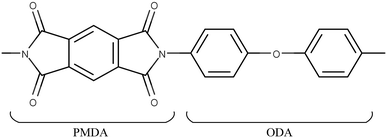
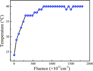
Polyimide films (PMDA-ODA, pyromellitic dianhydride-co-4,4′-oxydianiline) of 50 μm thick were supplied by China Academy of Space Technology. A schematic of the polymeric repeat unit of PMDA-ODA is shown in Fig. 1. The polyimide film was anisotropic, which was manufactured by tape casting process and then stored in rolls. In order to fit the following irradiation-load-heating coupling experiment, the samples were cut from the center with dog-bone shaped. The longitudinal direction of the polyimide sample, namely the loading direction in following tensile tests, was in accordance with machine direction of the film in order to prevent anisotropy effects.The electron beam irradiation was carried out in a ground-based simulation facility in Technical Physics Institute of Heilongjiang Academy of Sciences. The irradiations were carried out in air and the dimension of the effective electron beam area are about 100 mm × 500 mm. The electron fluence in this research varied from 5 × 10¹⁴ to 1 × 1016 cm−2 with an accelerative voltage of 1.2 MeV. During irradiation, the energy accumulation effect induced by electron beam will lead to temperature acceleration of polyimide films and the result is shown in Fig. 2. It can be seen that the temperature of polyimide films will increase gradually and then remain stable with the rising electron fluence. And the maximum temperature rise of polyimide films is about 15 °C. In order to further increase the temperature, extra heating device should be considered combined with electron beam irradiation.
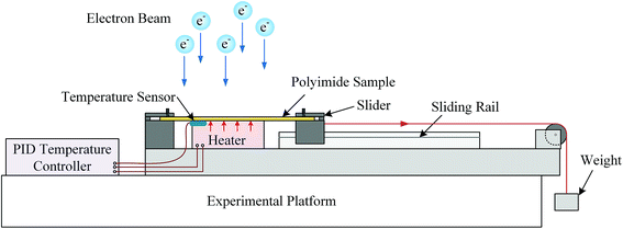
The irradiation-load-heating coupling experiment was conducted by self-designed equipment as shown in Fig. 3. The loading stress was controlled by the weight and sliding system, which was calibrated by force sensor before irradiation. The heating part was composed of temperature sensor, heater and PID controller. During coupling treatment, the temperature of the sample could be controlled by the feedback of temperature sensor attached to the polyimide film. Meanwhile, the wires connected with heater and temperature sensor were protected by ceramic tubes from electron beam irradiation. At the beginning of coupling treatment, the heater started firstly and the temperature of sample would reach target temperature before irradiation. In this work, the tensile stress and heating temperature were set as 50 MPa and 150 °C, respectively.
2.2 Characterization
The surface morphology of coupling treated polyimide films was observed by scanning electron microscope (SEM, SUPRA 55 SAPPHIRE, Zeiss). The phases of treated samples were identified by Panalytical Empyrean X-ray diffraction (XRD) with copper target. The scan step was 0.05° and the counting time was 0.4 s. The composition and chemical states after treatment were evaluated by X-ray photoelectron spectroscopy (XPS, ESCALAB250Xi, Thermo Fisher Scientific).Dynamic mechanical analysis was performed using a TA Instruments Q800. Storage and loss modulus (E′, E′′) were measured in temperature sweep mode (1 Hz, 3 °C min−1) at the temperature ranging from 40 to 450 °C. All measurements were performed under nitrogen atmosphere. The mechanical properties of the coupling treated polyimide films were measured at ambient temperature on tensile tester (INSTRON 5569) according to GB/T 1040-2006 standard. Before testing, the thickness of pristine and treated polyimide films was measured by thickness gauge to calculate cross-sectional area, which was in order to prevent the influence of creep effect during irradiation process. The strain rate was set to 3 mm min−1. The tensile strength and elongation were determined by the maximum stress and the strain, respectively; and the average values were calculated from the stress–strain curves for five polyimide samples at each treated parameter.
3. Results and discussion
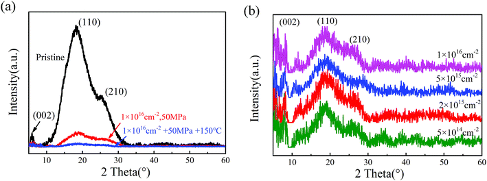
The results of X-ray diffraction patterns of the pristine polyimide film are presented in Fig. 4(a). It could be found that there are three Bragg's peaks at 5.8°, 18.2° and 25.3°, which could be indexed as (002), (110) and (210), respectively.32,33 It can be inferred that the semicrystalline structural pristine polyimide are still regularly ordered in certain degrees. When tensile stress of 50 MPa is applied, the molecular chains in polyimide tend to be stretched and much easier to be broken during high energy electron beam irradiation. Meanwhile, according to Arrhenius equation, the extra heating source increases the activating energy of molecular which lead to more severe chemical reaction in polyimide. Consequently, the coupling treatment contributes to the decline of crystallinity and disordering microstructure in polyimide samples. When irradiation-load-heating coupling treatment is applied, as shown in Fig. 4(b), the position of three strongest peaks have no change and the intensity of XRD patterns gradually decreased as the growing electron fluence. However, the relative intensity of (002) and (110) peak are much stronger than that in pristine polyimide, which indicates that there is a preferred orientation on (002) planes after irradiation-load-heating coupling treatment.The atomic ratio of C, O and N, calculated based on the XPS data, are shown in Fig. 5. The summation of C, O and N is set at 100% by neglecting the ratio of H in calculations. It can be seen that the contents of C and N drop dramatically after the irradiation-load-heating coupling treatment. Conversely, the O content significantly increases from 17.37% to 43.96%. It can be inferred that the process of severe oxidation, which is induced by coupling treatment, occurs in outer layer of polyimide films with increasing electron fluence. Eventually, the oxide layer is formed on polyimide films.
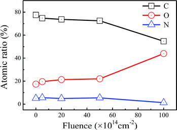 | ||
| Fig. 5 Atomic ratio of C, O and N in polyimide samples after irradiation-load-heating coupling treatment. | ||
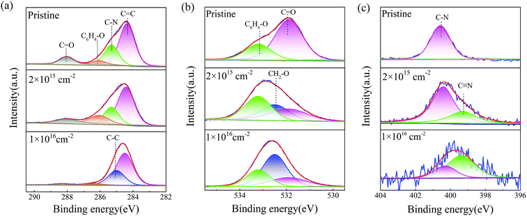
In order to investigate the chemical bonding states in polyimide samples after irradiation-load-heating coupling treatment, the analysis of core-level XPS spectra is introduced in Fig. 6. For C1s spectrum of the pristine sample as shown in Fig. 6(a), the prominent peak located at 284.5 eV corresponds to phenyl C![[double bond, length as m-dash]](https://www.rsc.org/images/entities/char_e001.gif) C bonds of ODA structure and the peak at 285.5 eV is related to C–N bonds in PMDA structure. The other two peaks at 286.3 eV and 288.4 eV are attributed to ether group C6H4–O in ODA unit and carbonyl group C
C bonds of ODA structure and the peak at 285.5 eV is related to C–N bonds in PMDA structure. The other two peaks at 286.3 eV and 288.4 eV are attributed to ether group C6H4–O in ODA unit and carbonyl group C![[double bond, length as m-dash]](https://www.rsc.org/images/entities/char_e001.gif) O in imide systems of PDMA unit, respectively.34 After irradiation-load-heating coupling treatment, the peak positions of C1s spectra have no modification. However, the relative intensities of these peaks have changed significantly. The detailed relative component ratios of different bonds are shown in Table 1. As electron fluence increases, the relative intensities of C
O in imide systems of PDMA unit, respectively.34 After irradiation-load-heating coupling treatment, the peak positions of C1s spectra have no modification. However, the relative intensities of these peaks have changed significantly. The detailed relative component ratios of different bonds are shown in Table 1. As electron fluence increases, the relative intensities of C![[double bond, length as m-dash]](https://www.rsc.org/images/entities/char_e001.gif) C, C–N and C
C, C–N and C![[double bond, length as m-dash]](https://www.rsc.org/images/entities/char_e001.gif) O bonds decrease. Meanwhile, new chemical bond, which is confirmed as aliphatic C–C bonds,35 forms when electron fluence rises up to 5 × 1015 cm−2. Moreover, the C
O bonds decrease. Meanwhile, new chemical bond, which is confirmed as aliphatic C–C bonds,35 forms when electron fluence rises up to 5 × 1015 cm−2. Moreover, the C![[double bond, length as m-dash]](https://www.rsc.org/images/entities/char_e001.gif) C and C–C bonds become the dominating components in C1s spectrum after coupling treatment with fluence of 1 × 1016 cm−2, and the ratios are 66% and 29.28%, respectively. However, the ratios of C6H4–O and C
C and C–C bonds become the dominating components in C1s spectrum after coupling treatment with fluence of 1 × 1016 cm−2, and the ratios are 66% and 29.28%, respectively. However, the ratios of C6H4–O and C![[double bond, length as m-dash]](https://www.rsc.org/images/entities/char_e001.gif) O peaks decrease significantly, and the peak of C–N bonds even totally disappears.
O peaks decrease significantly, and the peak of C–N bonds even totally disappears.
| Peaks | Bonds | Ebind (eV) | Proportion (%) | ||||
|---|---|---|---|---|---|---|---|
| Pristine | 5 × 1014 cm−2 | 2 × 1015 cm−2 | 5 × 1015 cm−2 | 1 × 1016 cm−2 | |||
| C1s | C![[double bond, length as m-dash]](https://www.rsc.org/images/entities/char_e001.gif) C C |
284.5 | 60.21 | 62.97 | 57.13 | 40.36 | 66 |
| C–C | 285.0 | — | — | — | 19.08 | 29.28 | |
| C–N | 285.5 | 25.95 | 25.96 | 21.83 | 20.25 | — | |
| C6H4–O | 286.3 | 4.65 | 3.49 | 13.79 | 13.26 | 2.94 | |
C![[double bond, length as m-dash]](https://www.rsc.org/images/entities/char_e001.gif) O O |
288.4 | 9.19 | 7.58 | 7.25 | 7.05 | 1.78 | |
| O1s | C![[double bond, length as m-dash]](https://www.rsc.org/images/entities/char_e001.gif) O O |
531.9 | 72.82 | 86.65 | 30.38 | 28.32 | 22.89 |
| CH2–O | 532.5 | — | — | 29.71 | 41.26 | 51.42 | |
| C6H4–O | 533.2 | 27.18 | 13.35 | 39.91 | 30.42 | 25.69 | |
| N1s | C![[triple bond, length as m-dash]](https://www.rsc.org/images/entities/char_e002.gif) N N |
399.4 | — | — | 30.28 | 43.43 | 70.06 |
| C–N | 400.3 | 100 | 100 | 69.72 | 56.57 | 29.94 | |
In Fig. 6(b), two deconvoluted signals are detected at 531.9 eV and 533.2 eV associated with carbonyl group (C![[double bond, length as m-dash]](https://www.rsc.org/images/entities/char_e001.gif) O) and ether group (C6H4–O), respectively. It can be seen that the ratio of C
O) and ether group (C6H4–O), respectively. It can be seen that the ratio of C![[double bond, length as m-dash]](https://www.rsc.org/images/entities/char_e001.gif) O decreases significantly with increasing electron fluence after coupling treatment, which is also confirmed by Table 1. Meanwhile, the ratio of C6H4–O relatively remains stable. When the fluence is over 2 × 1015 cm−2, a new bond detected at 532.5 eV, which can be assigned to ether group bonds CH2–O.35 Moreover, the ratio of CH2–O bonds reaches 51.42% as the fluence increasing to 1 × 1016 cm−2, which become the dominant role in O1s spectra. It can be inferred that there are several stages of the chemical bonds breakage. In the first stage, the carbonyl group (C
O decreases significantly with increasing electron fluence after coupling treatment, which is also confirmed by Table 1. Meanwhile, the ratio of C6H4–O relatively remains stable. When the fluence is over 2 × 1015 cm−2, a new bond detected at 532.5 eV, which can be assigned to ether group bonds CH2–O.35 Moreover, the ratio of CH2–O bonds reaches 51.42% as the fluence increasing to 1 × 1016 cm−2, which become the dominant role in O1s spectra. It can be inferred that there are several stages of the chemical bonds breakage. In the first stage, the carbonyl group (C![[double bond, length as m-dash]](https://www.rsc.org/images/entities/char_e001.gif) O) and ether group (C6H4–O) are more easily to break after coupling treatment. And the scissioning of carbonyl group might lead to formation of C–O· with free radical, which might be incorporate with other free radical such as C–C·. With increasing electron fluence, there are severe chemical bonds breakage of benzene ring in PMDA and ODA during coupling treatment, which facilitates to the increase of aliphatic C–C bonds and corresponding aliphatic ether group. Further, the increasing fluence during coupling treatment might also contribute to the formation of free radicals, which might be incorporated with each other or oxygen. Therefore, the coupling treatment leads to formation of new chemical bonds and oxide layer in outer layer polyimide films.
O) and ether group (C6H4–O) are more easily to break after coupling treatment. And the scissioning of carbonyl group might lead to formation of C–O· with free radical, which might be incorporate with other free radical such as C–C·. With increasing electron fluence, there are severe chemical bonds breakage of benzene ring in PMDA and ODA during coupling treatment, which facilitates to the increase of aliphatic C–C bonds and corresponding aliphatic ether group. Further, the increasing fluence during coupling treatment might also contribute to the formation of free radicals, which might be incorporated with each other or oxygen. Therefore, the coupling treatment leads to formation of new chemical bonds and oxide layer in outer layer polyimide films.
Fig. 6(c) shows the N1s spectra of untreated polyimide sample where only one symmetric peak at 400.3 eV (C–N) is detected. After the electron fluence rises up to 2 × 1015 cm−2, a new peak located at 399.4 eV is detected, which is assigned to C![[triple bond, length as m-dash]](https://www.rsc.org/images/entities/char_e002.gif) N bond arising from scissoning in imide structure and crosslinking between nitrogen and carbon under high dose of electron fluence irradiation, external tensile stress and high temperature. The ratio of C
N bond arising from scissoning in imide structure and crosslinking between nitrogen and carbon under high dose of electron fluence irradiation, external tensile stress and high temperature. The ratio of C![[triple bond, length as m-dash]](https://www.rsc.org/images/entities/char_e002.gif) N bonds rises up to 70.06% when samples treated with the fluence of 1 × 1016 cm−2. Moreover, the formation of C
N bonds rises up to 70.06% when samples treated with the fluence of 1 × 1016 cm−2. Moreover, the formation of C![[triple bond, length as m-dash]](https://www.rsc.org/images/entities/char_e002.gif) N bonds has been also observed when polyimide were irradiated by high energy beam.6,36,37
N bonds has been also observed when polyimide were irradiated by high energy beam.6,36,37
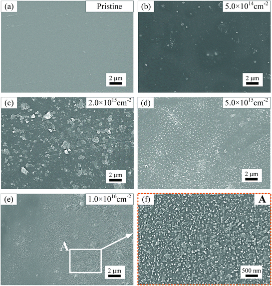
Fig. 7 shows SEM images of polyimide film surfaces after irradiation-load-heating coupling treatment with different electron fluences. Overall, the degree of surface degradation rises gradually with increasing fluence of electron. The surface of pristine polyimide film, as shown in Fig. 7(a), is quite smooth and there are no obvious defects on polyimide surface. When coupling treatment with electron fluence of 5 × 1014 cm−2 is applied, a small amount of round-shaped defects form on the surface of polyimide samples in Fig. 7(b). As electron fluence rises up to 2 × 1015 cm−2, the density and size of defects increase (Fig. 7(c)). With increase of fluence, however, the size of defects drops significantly. Meanwhile, there is a rapid growth of the amount of defects in Fig. 7(d) and the defects tend to be in round shape. When the electron fluence reaches 1 × 1016 cm−2, shown in Fig. 7(e) and corresponding enlarged area A in Fig. 7(f), the average diameter of defects further decreases to less than 100 nm, which uniformly distributed on polyimide surface. It can be inferred that electron fluence has a significant influence on surface morphology and quality of polyimide films during irradiation-load-heating coupling treatment. According to XPS results and SEM images, it can be confirmed that these defects are oxide products after coupling treatment.
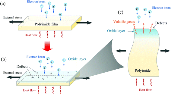
In process of coupling experiment, as shown in Fig. 8(a), the polyimide film is treated by high energy electron beam, external tension stress and high temperature. The irradiation of electron beam may lead to severe chemical reaction and thus scissioning of bonds in polyimide films, which may lead to the generation of volatile gases such as CO2, CO, nitrogen and hydrogen in polyimide matrix.30,38,39 Meanwhile, the reaction between free radicals induced by electron beam irradiation and oxygen in the air leads to formation of oxide products in the outer layer, which might be responsible for the formation of surface defects and oxide layer in the outer polyimide film.40 When tensile stress is applied, the free volume (the volume that is not occupied by polyimide chains) tends to increase, which would help to diffusion of oxygen into polyimide matrix, especially at the position of micro-cracks and defects.41,42 Consequently, the probability of free radical reactions increases, which might lead to an increased rate of degradation in the out layer of polyimide films.23 Moreover, heating help to increase its crosslinking in polyimide matrix and accelerate the process of oxidation via activating energy enhancement.43 Combining the effect of electron beam, tensile stress and heating, it can be concluded that the coupling treatment might lead to formation of oxide layer, surface defects and even volatile gases, just as illustration in Fig. 8(b) and corresponding enlarged cross-sectional schematic in Fig. 8(c). Moreover, the products of oxide layer and defects are confirmed by results XPS and SEM results, respectively. Based on these results, it can be inferred that the mechanical performance might tend to degrade after irradiation-load-heating coupling treatment due to the formation of defects and oxide layer.
The thermal–mechanical properties of PI films after coupling treatment are characterized by storage modulus (E′), loss modulus (E′′) and loss factor (tan![[thin space (1/6-em)]](https://www.rsc.org/images/entities/char_2009.gif) δ) from dynamic mechanical analysis measurements, as illustrated in Fig. 9. As the temperature increases, E′ of the pristine sample decreases gradually but distinctly from 375 to 425 °C as shown in Fig. 9(a), which is related with energy dissipation involving cooperative motions of the polymer chains with temperature.44 By comparison with pristine and coupling treated polyimide samples, the E′ curve drops with increasing electron fluence. When the sample is irradiated by fluence of 1 × 1016 cm−2, E′ of the treated sample produces a significant decrease of 61% from 2570 to 1012 MPa at 40 °C. It can be inferred that the degradation effects of the coupling treatment lead to decreased stiffness of polyimide films.45
δ) from dynamic mechanical analysis measurements, as illustrated in Fig. 9. As the temperature increases, E′ of the pristine sample decreases gradually but distinctly from 375 to 425 °C as shown in Fig. 9(a), which is related with energy dissipation involving cooperative motions of the polymer chains with temperature.44 By comparison with pristine and coupling treated polyimide samples, the E′ curve drops with increasing electron fluence. When the sample is irradiated by fluence of 1 × 1016 cm−2, E′ of the treated sample produces a significant decrease of 61% from 2570 to 1012 MPa at 40 °C. It can be inferred that the degradation effects of the coupling treatment lead to decreased stiffness of polyimide films.45
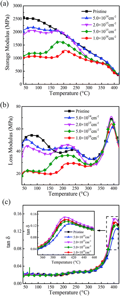 | ||
| Fig. 9 Dynamic mechanical properties of polyimide films after irradiation-load-heating coupling treatment with different electron fluence. (a) Storage modulus; (b) loss modulus; (c) loss factor. | ||
In Fig. 9(b), the broad peaks of E′′ at 250 and 390 °C in pristine polyimide are known as transitions due to the rotation of aromatic rings (β-transition) and the segmental motion of the backbone (α-transition), respectively.43 It can be seen that the intensity of E′′ curve tends to decrease for coupling treated polyimide films with increasing electron fluence. Moreover, β-transition shifts to lower-temperatures when the polyimide films are irradiated by fluence more than 2 × 1015 cm−2. As the decreased loss modulus is caused by the drop of friction between molecular chains, it can be concluded that the coupling treatment contributes to the scissioning of chemical bonds in polyimides samples as electron fluence increases.
Fig. 9(c) shows the loss factor of polyimide samples, which is the ratio of E′′ to E′. Tg, which is taken from the peak temperature of the tan![[thin space (1/6-em)]](https://www.rsc.org/images/entities/char_2009.gif) δ curve and also known as glass transition temperature, provides direct insight into the segmental mobility of macromolecular chains.45 After the coupling treatment by the fluence of 5 × 1014 cm−2, Tg increases from 405.4 °C to 412.5 °C and the rise in the glass transition temperature could be attributed to an increasing crosslinking in polyimide.31 After that, Tg decreases gradually with the increase of electron fluence. When the electron fluence is 1 × 1016 cm−2, the value of Tg reaches 404.5 °C, which drops 0.9 °C comparing with the pristine one. Consequently, when the electron fluence is low, the scissioning effect is relatively weak and crosslinking effect dominates after coupling treatment, which contribute to the increase of Tg. As electron fluence increases, however, the scissioning effect plays a key role and thus enhances the mobility of molecular chains in polyimide films.
δ curve and also known as glass transition temperature, provides direct insight into the segmental mobility of macromolecular chains.45 After the coupling treatment by the fluence of 5 × 1014 cm−2, Tg increases from 405.4 °C to 412.5 °C and the rise in the glass transition temperature could be attributed to an increasing crosslinking in polyimide.31 After that, Tg decreases gradually with the increase of electron fluence. When the electron fluence is 1 × 1016 cm−2, the value of Tg reaches 404.5 °C, which drops 0.9 °C comparing with the pristine one. Consequently, when the electron fluence is low, the scissioning effect is relatively weak and crosslinking effect dominates after coupling treatment, which contribute to the increase of Tg. As electron fluence increases, however, the scissioning effect plays a key role and thus enhances the mobility of molecular chains in polyimide films.
The mechanical properties after irradiation-load-heating coupling treatment with different electron fluence are shown in Fig. 10. From the comparison of stress–strain curves between pristine and coupling treated polyimide samples in Fig. 10(a), it can be clearly observed that the treated polyimide samples exhibit a higher tensile strength than that of pristine one after low fluence of electron irradiation. As shown in Fig. 10(b), when the electron fluence is 5 × 1014 cm−2, the tensile strength and elongation of irradiated polyimide sample reach 196.1 MPa and 89.4% respectively. After that, the mechanical properties decrease gradually with the increase of electron fluence. When the electron fluence is 1 × 1016 cm−2, the tensile strength and elongation of irradiation-load-heating treated polyimide sample drop 5.9% and 23.6%, respectively, comparing with the pristine one. The behavior of mechanical performance may be caused by the microstructural variation during coupling treatment. When low electron fluence is applied, there is a slight increase of tensile strength, which mainly caused by the fact that crosslinking has a dominant effect during this period. As the fluence increase, the molecular chains tend to be broken easily after high dose of irradiation and the effect of scissioning plays a key role. Besides, the formation of oxide layer and defects illustrated in Fig. 8(c) might facilitate the initiation of crack propagation and thus decrease the mechanical properties. Therefore, the irradiation-load-heating coupling treatment accelerates the degradation process.
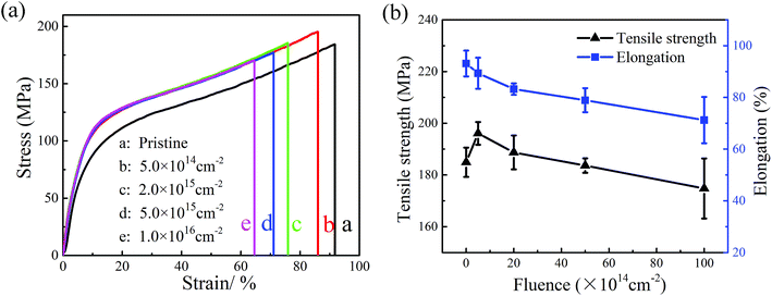 | ||
| Fig. 10 Mechanical properties of the polyimide films after irradiation-load-heating coupling treatment with different electron fluence. (a) Stress–strain curves; (b) tensile strength and elongation. | ||
4. Conclusions
In the present work, the degradation behavior of polyimide films induced by coupling treatment using self-designed equipment, combined with different doses of high energy electron (1.2 MeV), heavy tensile stress (50 MPa) and high temperature (150 °C), has been investigated. When coupling treatment is applied, there is a significant decline of crystallinity in polyimide films. Meanwhile, new chemical bonds of C–C and CH2–O and C![[triple bond, length as m-dash]](https://www.rsc.org/images/entities/char_e002.gif) N formed after coupling treatment. Moreover, the coupling treatment might contribute to the formation of an oxide layer, surface defects and even volatile gases. This is caused by the significant scissioning of molecular chains in polyimide films and corresponding chemical reactions between free radicals and oxygen in the air. Consequently, the irradiation-load-heating coupling treatment led to a remarkable drop in viscoelastic properties and mechanical performance of polyimide films, thereby accelerating the degradation of polyimide films.
N formed after coupling treatment. Moreover, the coupling treatment might contribute to the formation of an oxide layer, surface defects and even volatile gases. This is caused by the significant scissioning of molecular chains in polyimide films and corresponding chemical reactions between free radicals and oxygen in the air. Consequently, the irradiation-load-heating coupling treatment led to a remarkable drop in viscoelastic properties and mechanical performance of polyimide films, thereby accelerating the degradation of polyimide films.
Conflicts of interest
The authors declare that they have no conflicts of interest.Acknowledgements
The authors warmly thank Dr Dian Luo for the help of SEM tests and data analysis.References
- D.-J. Liaw, K.-L. Wang, Y.-C. Huang, K.-R. Lee, J.-Y. Lai and C.-S. Ha, Prog. Polym. Sci., 2012, 37, 907–974 CrossRef.
- N. Atar, E. Grossman, I. Gouzman, A. Bolker, V. J. Murray, B. C. Marshall, M. Qian, T. K. Minton and Y. Hanein, ACS Appl. Mater. Interfaces, 2015, 7, 12047–12056 CrossRef PubMed.
- T. Steckenreiter, E. Balanzat, H. Fuess and C. Trautmann, J. Polym. Sci., Part A: Polym. Chem., 1999, 37, 4318–4329 CrossRef.
- V. Svorcık, K. Proskova, V. Hnatowicz, E. Arenholz and A. Kluge, Polym. Degrad. Stab., 1999, 65, 131–135 CrossRef.
- N. Mathakari, V. Jadhav, D. Kanjilal, V. Bhoraskar and S. Dhole, Surf. Coat. Technol., 2009, 203, 2620–2624 CrossRef.
- S. K. Gupta, R. Gupta, P. Singh, V. Kumar, M. K. Jaiswal, S. Chakarvarti and R. Kumar, Nucl. Instrum. Methods Phys. Res., Sect. B, 2017, 406, 188–192 CrossRef.
- G. Schoeppner, G. Tandon and E. Ripberger, Composites, Part A, 2007, 38, 890–904 CrossRef.
- R. Verker, N. Atar, F. Quero, S. Eichhorn and E. Grossman, Polym. Degrad. Stab., 2013, 98, 997–1005 CrossRef.
- L. Yue, Y. Wu, C. Sun, Y. Shi and Y. Zhang, Radiat. Phys. Chem., 2016, 119, 130–135 CrossRef.
- M. Lv, F. Zheng, Q. Wang, T. Wang and Y. Liang, Wear, 2014, 316, 30–36 CrossRef.
- H. Shimamura and T. Nakamura, Polym. Degrad. Stab., 2010, 95, 21–33 CrossRef.
- T. Seidl, A. Plotnikov, E. Mustafin, R. Lopez, D. Severin, E. Floch, C. Trautmann, A. Golubev, A. Smolyakov and D. Tommasini, Polym. Degrad. Stab., 2012, 97, 2396–2402 CrossRef.
- N. L. Mathakari, V. N. Bhoraskar and S. D. Dhole, Mater. Sci. Eng., B, 2010, 168, 122–126 CrossRef.
- K. Vanherck, G. Koeckelberghs and I. F. Vankelecom, Prog. Polym. Sci., 2013, 38, 874–896 CrossRef.
- C. Sun, Y. Wu, L. Yue, Y. Shi and J. Xiao, Nucl. Instrum. Methods Phys. Res., Sect. B, 2012, 271, 61–64 CrossRef.
- C.-C. Lin, L.-J. Ming, C.-C. Lee and S. Lee, Polymer, 2008, 49, 3987–3992 CrossRef.
- D. P. Engelhart, E. Plis, S. Humagain, S. Greenbaum, D. Ferguson, R. Cooper and R. Hoffmann, IEEE Trans. Plasma Sci., 2017, 45, 2573–2577 Search PubMed.
- S. Kucheyev, T. Felter, M. Anthamatten and J. Bradby, Appl. Phys. Lett., 2004, 85, 733–735 CrossRef.
- J. Shi, C. Gong, X. Tian, S. Yang and P. K. Chu, Appl. Surf. Sci., 2012, 258, 3829–3834 CrossRef.
- H. Shimamura and T. Nakamura, Polym. Degrad. Stab., 2009, 94, 1389–1396 CrossRef.
- T. Chen, S. Yao, K. Wang, H. Wang and S. Zhou, Surf. Coat. Technol., 2009, 203, 3718–3721 CrossRef.
- Y. Wu, C. Sun, J. Xiao, R. Li, D. Yang and S. He, Polym. Degrad. Stab., 2010, 95, 1219–1225 CrossRef.
- R. Verker, E. Grossman, I. Gouzman and N. Eliaz, High Perform. Polym., 2008, 20, 475–491 CrossRef.
- J. D. Johnston and E. A. Thornton, J. Spacecr. Rockets, 2000, 37, 604–613 CrossRef.
- A. De Luca, Architectural design criteria for spacecraft solar arrays, InTech, 2011 Search PubMed.
- X. Lu, X. Wang, Q. Li, X. Huang, S. Han and G. Wang, Polym. Degrad. Stab., 2015, 114, 72–80 CrossRef.
- L. Li, C. Guan, A. Zhang, D. Chen and Z. Qing, Polym. Degrad. Stab., 2004, 84, 369–373 CrossRef.
- K. Pramoda, T. Chung, S. Liu, H. Oikawa and A. Yamaguchi, Polym. Degrad. Stab., 2000, 67, 365–374 CrossRef.
- G. Tandon, K. Pochiraju and G. Schoeppner, Mater. Sci. Eng., 2008, 498, 150–161 CrossRef.
- R. Khazaka, M. Locatelli, S. Diaham and P. Bidan, Polym. Degrad. Stab., 2013, 98, 361–367 CrossRef.
- M. Ruggles and J. Broeckert, J. Appl. Polym. Sci., 2009, 111, 228–236 CrossRef.
- T. J. Shin, B. Lee, H. S. Youn, K.-B. Lee and M. Ree, Langmuir, 2001, 17, 7842–7850 CrossRef.
- J. Wang, X. Zhao, E. B. Berda, C. Chen, K. Wang, S. Chen, B. Zou, B. Liu, Q. Zhou and F. Li, Polymer, 2016, 90, 1–8 CrossRef.
- A. Ektessabi and S. Hakamata, Thin Solid Films, 2000, 377, 621–625 CrossRef.
- G. Beamson and D. Briggs, High Resolution XPS of Organic Polymers, 1992, pp. 92–178 Search PubMed.
- R. Li, C. Li, S. He, M. Di and D. Yang, Radiat. Phys. Chem., 2008, 77, 482–489 CrossRef.
- L. Novikov, E. Voronina, V. Chernik, L. Zhilyakov and N. Chirskaya, Nucl. Instrum. Methods Phys. Res., Sect. B, 2017, 410, 60–67 CrossRef.
- R. Verker, E. Grossman, I. Gouzman and N. Eliaz, Polymer, 2007, 48, 19–24 CrossRef.
- Z. Iskanderova, J. Kleiman, V. Issoupov, S. Naumov, S. Sokolova, A. Kurilenok, L. Novikov, V. Chernik, A. Grigorevskiy and L. i. Kiseleva, Critical Evaluation of Testing Results for Russian and Western Space Materials in Ground-Based Simulator Facilities and in Space Experiments, Springer, 2013 Search PubMed.
- T. K. Tsotsis, S. Keller, J. Bardis and J. Bish, Polym. Degrad. Stab., 1999, 64, 207–212 CrossRef.
- M. Klopffer and B. Flaconneche, Oil Gas Sci. Technol., 2001, 56, 223–244 CrossRef.
- D. R. Tyler, J. Macromol. Sci., Part C: Polym. Rev., 2004, 44, 351–388 CrossRef.
- M. Pecht and X. Wu, IEEE Trans. Compon., Packag., Manuf. Technol., Part B, 1994, 17, 632–639 CrossRef.
- X. Wang, L.-X. Gong, L.-C. Tang, K. Peng, Y.-B. Pei, L. Zhao, L.-B. Wu and J.-X. Jiang, Composites, Part A, 2015, 69, 288–298 CrossRef.
- C. Shi, S. Liu, Y. Li, Y. Yuan, J. Zhao and Y. Fu, Compos. Sci. Technol., 2017, 142, 117–123 CrossRef.
| This journal is © The Royal Society of Chemistry 2018 |

