 Open Access Article
Synthesis of ZSM-5/KIT-6 with a tunable pore structure and its catalytic application in the hydrodesulfurization of dibenzothiophene and diesel oil
Qi Gaoa,
Yan Zhang†
a,
Kangdi Zhoua,
Huadong Wu *a,
Jia Guo*a,
Linfeng Zhanga,
Aijun Duan
 b,
Zhen Zhao
 b,
Fuqing Zhanga and
Yuxin Zhoua
aKey Laboratory of Green Chemical Process of Ministry of Education, Hubei Key Laboratory of Novel Chemical Reactor and Green Chemical Technology, Wuhan Institute of Technology, Wuhan 430073, P. R. China. E-mail: wuhuadong@wit.edu.cn; guojia@wit.edu.cn; Tel: +86-027-87194980
bState Key Laboratory of Heavy Oil Processing, China University of Petroleum, Beijing, P. R. China
First published on 14th August 2018
Abstract
Porous support materials were prepared by assembling primary and secondary ZSM-5 structural units into a well-ordered mesoporous framework. The materials possessed both ZSM-5 microporous building units and mesoporous structure were used as supports for the preparation of hydrodesulfurization (HDS) catalysts. The materials and their corresponding catalysts were characterized by XRD, FTIR, 27Al MAS NMR, TEM, N2 adsorption–desorption, Py-FTIR, H2-TPR, Raman, and HRTEM techniques. The pore structures of the composite materials were modulated by adjusting the molar ratio of butanol/P123 (BuOH/P123) and then, the influences of BuOH/P123 on the catalytic performance in the HDS of dibenzothiophene (DBT) and diesel oil were systematically studied. The results showed that butanol has a big influence on the structure of the micro–mesoporous material, whereby different micro–mesoporous structures, such as the p6mm hexagonal structure or Ia![[3 with combining macron]](https://www.rsc.org/images/entities/char_0033_0304.gif) d cubic structure, were formed with different butanol addition amounts. The composite ZK-3 (BuOH/P123 = 100) possessed the best surface area and pore structure. Therefore, the NiMo/ZK-3 catalyst showed the highest catalytic activity in the HDS of DBT with a BP selectivity of 72.1% due to its excellent textural property, moderate MSI, relatively high B/L ratios, and highly dispersed NiMoS active phases. Moreover, the NiMo/AZK-3 catalyst exhibited excellent catalytic performance in the HDS of diesel oil.
d cubic structure, were formed with different butanol addition amounts. The composite ZK-3 (BuOH/P123 = 100) possessed the best surface area and pore structure. Therefore, the NiMo/ZK-3 catalyst showed the highest catalytic activity in the HDS of DBT with a BP selectivity of 72.1% due to its excellent textural property, moderate MSI, relatively high B/L ratios, and highly dispersed NiMoS active phases. Moreover, the NiMo/AZK-3 catalyst exhibited excellent catalytic performance in the HDS of diesel oil.
1. Introduction
Along with the increased attention being paid to environmental pollution worldwide, most countries have enacted laws or regulations to restrict the sulfur content in transportation fuel. In order to fulfill the strict fuel standards set by the government regarding the sulfur content (<10 ppm), the removal of some sulfides with a benzene ring, especially intractable heterocyclic organic sulfides, like dibenzothiophene (DBT) and 4,6-dimethyldibenzothiophene (4,6-DMDBT), from transportation fuel is crucial.1–6 Until now, hydrodesulfurization (HDS) technology has been an effective method utilized for the large-scale production of clean oil. Thus, the preparation of highly active catalysts is of much significance for an efficient HDS process.7–10It is well known that the open pore structure can promote the diffusion of reactants and the accessibility of active sites, which can greatly improve the desulfurization performance of a catalyst.11,12 Therefore, many mesoporous materials are applied as catalyst supports, such as MCM-41,13,14 MCM-36,15 SBA-15 (ref. 16–20), KIT-6.21 Kim et al.22,23 successfully synthesized KIT-6 (6–12 nm) mesoporous material with an Ia![[3 with combining macron]](https://www.rsc.org/images/entities/char_0033_0304.gif) d cubic structure by employing P123 together with n-butanol (BuOH) as mixed templating agents. The material was demonstrated to have connecting pores (∼1.7 nm) besides two sets of three-dimensional (3D) helical main channels. An interactive net-like structure was formed between the main channel, which evidently promoted the diffusion and reaction of large molecules. This novel kind of material KIT-6 with thick pore walls, high hydrothermal stability, and a high specific surface area has aroused great attention for its potential applications in different catalysis processes.24
d cubic structure by employing P123 together with n-butanol (BuOH) as mixed templating agents. The material was demonstrated to have connecting pores (∼1.7 nm) besides two sets of three-dimensional (3D) helical main channels. An interactive net-like structure was formed between the main channel, which evidently promoted the diffusion and reaction of large molecules. This novel kind of material KIT-6 with thick pore walls, high hydrothermal stability, and a high specific surface area has aroused great attention for its potential applications in different catalysis processes.24
However, the lack of B acid cites has limited the wide application of pure mesoporous materials. In order to promote the acidity, on the one hand, mesoporous zeolite Y, Beta, and ZSM-5 were synthesized.8 Fu et al. prepared different kinds of mesoporous material-supported HDS catalysts; the resulting catalysts all exhibited high activities in the HDS of 4,6-DMDBT compared with γ-Al2O3-supported Pd catalysts.8 On the other hand, building units of microporous zeolite were introduced into the framework of the mesoporous wall, thus they are named micro–mesoporous composite materials. Different varieties of these kinds of materials have been used as supports to prepare HDS catalysts, including MFI/MCM-41,25 Beta-KIT-6 (BK),26 and L-KIT-6 (LK).27 Österholm et al. prepared the micro–mesoporous composite material MFI/MCM-41 by a nano-assembly method.28 The results showed that with increasing the Al content in the composite, the total acid and B acid were increased at the same time, and the degree the mesostructure was retained was higher than that of pure MCM-41 when the composite material was calcined at 1173 K, which indicated that the introduction of micropores into the mesoporous composite improved the stability of the material.28 Zhang26 synthesized the micro–mesoporous material BK, which contained both a Beta and KIT-6 bimodal pore distribution. The catalytic performance of NiMo/BK over DBT was much better than that of both NiMo/Beta and NiMo/KIT-6. CoMo/LK prepared by Duan et al.27 possessed a similar mesoporous structure of CoMo/KIT-6, and it was found that the HDS efficiency of benzothiophene (BT) over the CoMo/LK catalyst was higher than that of CoMo/KIT-6 at all liquid hourly space velocities (LHSVs), and about twice that of CoMo/L. All of this indicated that micro–mesoporous materials, which combine the advantage of a porous structure and acidity, were beneficial to the diffusion of sulfides with a large molecular size and enhanced the HDS catalytic performances of catalysts. Among the different kinds of zeolites, nanocrystalline ZSM-5 is a versatile material due to its excellent hydrogenation and isomerization performance. In our previous work, we found that mesoporous KIT-6 silica-enwrapped nano-sized ZSM-5 zeolite crystals were an efficient HDS catalyst support,29 and that the acidities and diffuse properties of the composites were much stronger than those of the mechanical mixtures of ZSM-5 and KIT-6. Therefore, the micro–mesoporous material ZSM-5/KIT-6 (ZK), prepared by assembling the ZSM-5 primary and secondary building units into the framework of the KIT-6 mesoporous structure, may have better performance than the composite we prepared before.
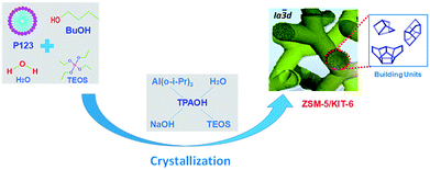
Though KIT-6 based micro–mesoporous materials of Beta-KIT-6 and L-KIT-6 have previously been synthesized successfully, the role of mixing in a structure-directing template has not yet been studied deeply, to the best of our knowledge, especially the molar ratio of BuOH/P123. Specifically, as far as we know, there are no reports about how to change the pore structure of the novel micro–mesoporous material ZK by changing the ratio of BuOH/P123. Consequently, we synthesized the composite material ZK using a two-step hydrothermal crystallization method by assembling the nano-sized ZSM-5 precursor into a well-ordered Ia![[3 with combining macron]](https://www.rsc.org/images/entities/char_0033_0304.gif) d cubic mesoporous structure in this work. In order to modulate the physicochemical properties of the micro–mesoporous material ZK to ensure that the novel material has an open pore structure, a series of composites were prepared with different amounts of n-butanol. The as-synthesized ZK materials were then employed as supports to prepare different NiMo-supported catalysts, notably, a series of catalysts were evaluated over DBT and diesel oil for the first time. NiMo supported on ZSM-5, KIT-6, and Al2O3 catalysts were also prepared for comparison.
d cubic mesoporous structure in this work. In order to modulate the physicochemical properties of the micro–mesoporous material ZK to ensure that the novel material has an open pore structure, a series of composites were prepared with different amounts of n-butanol. The as-synthesized ZK materials were then employed as supports to prepare different NiMo-supported catalysts, notably, a series of catalysts were evaluated over DBT and diesel oil for the first time. NiMo supported on ZSM-5, KIT-6, and Al2O3 catalysts were also prepared for comparison.
2. Experimental
2.1. Synthesis of the supports
![[thin space (1/6-em)]](https://www.rsc.org/images/entities/char_2009.gif) :
:![[thin space (1/6-em)]](https://www.rsc.org/images/entities/char_2009.gif) Al2O3 molar ratio of 90) was prepared in the same way as described above, but the crystallization temperature and time were extended to 170 °C and 48 h, respectively. Mesoporous silica KIT-6 was prepared based on the reported literature.22,31
Al2O3 molar ratio of 90) was prepared in the same way as described above, but the crystallization temperature and time were extended to 170 °C and 48 h, respectively. Mesoporous silica KIT-6 was prepared based on the reported literature.22,312.2. Preparation of the NiMo-supported catalysts
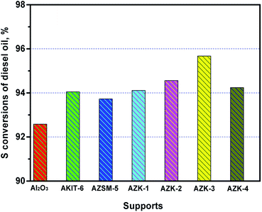
The NiMo-supported catalysts were prepared by a two-step incipient-wetness impregnation method. First, the obtained ZK materials were ion exchanged with 1.0 M ammonium chloride solution at 80 °C for 2 h, and then the composites were filtered, washed, dried, and calcinated in the same way as described above. Mo and Ni were then impregnated, respectively. Calcination was carried out after each impregnation. Finally, catalysts with 10 wt% MoO3 loading and 3.5 wt% NiO loading were prepared. Meanwhile, NiMo/Al2O3, NiMo/ZSM-5, and NiMo/KIT-6 catalysts with the same loading of active metals were also prepared as reference catalysts. In addition, a part of the synthesized materials was mixed with Al2O3, whereby the weight of Al2O3 was four times that of the synthesized materials. Those Al2O3-doped mixtures were also used as supports to prepare NiMo-supported catalysts, which were only used for the HDS of diesel oil, and these mixtures of supported NiMo catalysts were denoted as NiMo/AZK-1, NiMo/AZK-2, NiMo/AZK-3, NiMo/AZK-4, NiMo/AZSM-5, and NiMo/AKIT-6.2.3. Characterization of the supports and catalysts
Wide-angle X-ray diffraction (XRD) patterns of the supports and catalysts were tested using an X-ray diffractometer (D8 ADVANCE and DAVINCI DESIGN) using CuKα (40 kV, 40 mA) radiation in the 2θ range from 5–90° at a scanning rate of 1° min−1. For small-angle XRD, the samples were tested on a diffractometer of PANalytical B.V. (X'Pert PRO) using CuKα (60 kV, 55 mA) radiation. Here, 2θ ranged from 0.5–5°. FTIR absorbance spectra were recorded using a Nicolet 6700 spectrometer (American Thermo Electron) with the wavenumber range 1200–400 cm−1. The detected slices were handled by KBr tabletting with a weight ratio of 100 KBr:1 sample. 27Al MAS NMR spectra were recorded with a Bruker Avance III 500 MHz spectrometer at 130 MHz with a 0.9 μs pulse width, 6 μs delay time, and 12 kHz spinning speed. TEM images were detected on a JEOL JEM 2100 electron microscope with a testing voltage of 200 kV, Cs = 0.5 mm. Before testing, the materials were ground in an agate mortar, and subsequently dispersed in absolute ethanol under ultrasonic conditions for about 20 min. After that, two drops of the supernatant liquid were dripped on to an ultrathin copper grid coated with a sputtered carbon polymer. The textural properties of the synthesized materials were obtained by nitrogen adsorption–desorption with ASAP 2020 at −196 °C. The specific surface areas of these materials were calculated by the BET model. The pore size distribution (PSD) was acquired from the desorption branch of the isotherms using the BJH method. The total pore volumes were gained from the amounts of nitrogen absorbed at a relative pressure P/P0 of 0.98. The acidity of the catalysts were taken from pyridine-FTIR (Py-FTIR) spectroscopy on a MAGNAIR 560 FTIR instrument (Nicolet Co., US) with a resolution of 1 cm−1. The samples were pretreated under 500 °C for 5 h with a vacuum of 1.33 × 10⁻³ Pa, and subsequently absorbed pyridine vapor at room temperature for 20 min. Then, the system was degassed at 473 K and 623 K respectively, and the IR spectra were recorded at the same time. H2-TPR analyses were performed on a Quantachrome apparatus (Autosorb-iQ, USA). Here, 100 mg sample was pretreated under air atmosphere by calcination at 300 °C for 1 h and subsequently cooled to 30 °C. Then, 10% H2/Ar flow (40 ml min−1) was passed over the catalyst bed while the temperature was ramped from 30 °C to 600 °C at a heating rate of 10 °C min−1. The hydrogen consumption signal was recorded by a TCD detector. The Raman shift spectra were performed on a Raman spectrometer (Renishaw Micro-Raman System 2000) operating at a laser wavelength of 325 nm. The wave number ranged from 1600 to 200 cm−1. The size of the laser spot was about 1–2 mm with a power of 8 mW. The HRTEM images were observed through a Philips Tecnai G2 F20 S-TWIN system. The catalysts were presulfided in a flow of cyclohexane containing 2.5 wt% CS2 at 340 °C for 4 h to make sure that the molybdenum oxide was exchanged to NiMoS. After that, the sulfided catalysts were collected and sealed in cyclohexane to prevent oxidation.2.4. Catalyst evaluation
The catalytic performances of the different NiMo/ZK catalysts were investigated using DBT (dissolved in cyclohexane with 600 ppm S) as the reactant molecule. The catalysts were presulfided first under a H2 flow at 320 °C, 4 MPa. The presulfided process lasted for about 4 h. The catalyst weight was 0.5 g; then the particle size of the catalysts and quartz sand were all crushed to 40–60 mesh. HDS reactions were carried out at 4 MPa and 340 °C with a H2/oil ratio of 200 ml ml−1. The reaction products were analyzed by offline Finnigan Trace GC-MS with a Trace Ultral gas chromatograph using a HP-5MS (60 m × 0.25 mm × 0.25 μm) capillary column and a pulsed flame photometric detector (PFPD).In addition, the HDS activities evaluation of diesel oil over the prepared NiMo/Al-ZK catalysts were further investigated on a high-pressure hydrogenation micro-reactor using 2.5 wt% CS2 in cyclohexane for presulfidation. Here, 2.00 g of the catalysts (40–60 mesh) blended with quartz sand were loaded in a reaction tube with a pipe diameter of 8 mm and length of about 400 mm. The catalysts were presulfided first and then the pressure and temperature were raised to 5 MPa and 350 °C, respectively. The raw diesel oil was injected into the reactor through a SZB-2 double-piston pump. Then the reaction was carried out at 5 MPa, 350 °C, and a H2/oil ratio of 300 ml ml−1. When the reaction reached a steady state, the product samples were collected every 2 h. All the liquid samples were collected after the reaction reaching the stable state and were measured by a RPP-2000 SN sulfur and nitrogen analyzer (Taizhou Central Analytical Instruments Co. Ltd. P. R. China).
3. Results and discussion
3.1. XRD results
In order to control the formation of the building units of ZSM-5 seeds in the preparation process of the ZK composite material, the crystallization process of ZSM-5 was investigated. ZSM-5 samples were synthesized at different crystallization times from 12 h to 72 h. Their relative crystallinities, which is defined as the area ratio of the characteristic peaks of as-synthesized ZSM-5 with different crystallization times and standard ZSM-5, were calculated. XRD patterns in wide-angle (A) and the relative crystallinity (B) of ZSM-5 are shown in Fig. 2. The ZSM-5 seed obtained at the crystallization time of 12 h exhibited a relatively weak diffraction peak, indicating that the primary and secondary structural units were beginning to form. The intensities of the diffraction peaks increased as the crystallization time increased, suggesting that nanocrystalline particles of the ZSM-5 crystals were being generated. Therefore, a ZSM-5 crystalline emulsion with the crystallization time of 24 h could be easily assembled using a mesoporous structure-directing agent suitable for the synthesis of ZK composite material. With the increasing crystallization time, the ZSM-5 zeolite particles became bigger, and could hardly be assembled in the mesoporous wall. The crystallinity degrees of ZSM-5 with the crystallization time of 48 h and 72 h were relatively high, with many sharp peaks clearly observable at 2θ = 7.9°, 8.8°, 20.3°, 23.1°, 23.9°, and 29.9°, corresponding to the (101), (200), (103), (501), (303), and (303) planes.23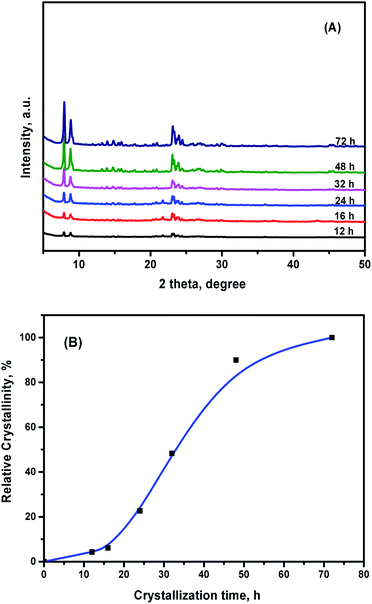 | ||
| Fig. 2 XRD patterns in wide-angle (A) and the relative crystallinity (B) of ZSM-5 obtained at different crystallization times. | ||
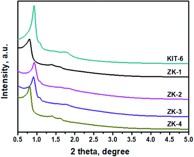
XRD patterns of the ZK materials in a small-angle domain with a crystallization time of 24 h for the ZSM-5 emulsion are shown in Fig. 3. These materials exhibit different characteristic peaks when the amount of n-butanol is varied. The results show that different micro–mesoporous structures, such as p6mm hexagonal or 3D cubic, were formed with the different butanol addition amounts. ZK-1 and ZK-4 display typical SBA-15 characteristic peaks relating to its (100), (110), and (200) planes,16 while ZK-2 and ZK-3 exhibit the characteristic peaks of KIT-6. The results indicate that the composites ZK-1 and ZK-4 may possess the p6mm mesostructure of SBA-15, while ZK-2 and ZK-3 may own the cubic Ia![[3 with combining macron]](https://www.rsc.org/images/entities/char_0033_0304.gif) d structure of KIT-6. The obvious peaks at 2θ ≈ 0.9° refers to the reflection of (211), while a slightly recognizable hump at around 1.1° refers to the reflection of (220). In addition, several small uplifts of spectra lines between 1.3° and 1.9° under amplification conditions were considered responsible for the lattice planes of (321), (400), (420), and (332). The results indicate that the as-synthesized materials ZK-2 and ZK-3 may own the characteristic structure of KIT-6 with the body-centered cubic Ia
d structure of KIT-6. The obvious peaks at 2θ ≈ 0.9° refers to the reflection of (211), while a slightly recognizable hump at around 1.1° refers to the reflection of (220). In addition, several small uplifts of spectra lines between 1.3° and 1.9° under amplification conditions were considered responsible for the lattice planes of (321), (400), (420), and (332). The results indicate that the as-synthesized materials ZK-2 and ZK-3 may own the characteristic structure of KIT-6 with the body-centered cubic Ia![[3 with combining macron]](https://www.rsc.org/images/entities/char_0033_0304.gif) d space structure.32
d space structure.32
3.2. FTIR results
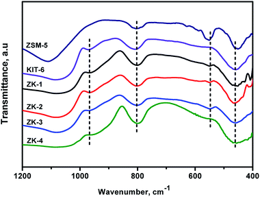
The FTIR spectra of ZSM-5, KIT-6, and the ZK composites in the domain of 400–1200 cm−1 are displayed in Fig. 4. The framework vibration spectra of ZK samples exhibit the obvious vibration patterns of KIT-6 centered at ∼460, 805, 970, and 1080 cm−1.29 The adsorption band around 460 cm−1 represents the Si–O–Si bending vibrations, while the band at 805 cm−1 represents the symmetric stretching vibrations of Si–O–Si bonds.33 In addition, the adsorption peak at 1080 cm−1 could be assigned to the asymmetric stretching vibrations of Si–O–Si bonds. The band at 970 cm−1 was ascribed to the defective Si–OH group.17Noteworthily, the ZK samples also displayed weak bands at ∼570 cm−1, which were a little red-shifted compared with the ZSM-5 characteristic band at 550 cm−1, and these represent the typical vibration bands of five- or six-membered rings of X–O–X, where X can be Al or Si. Because the Si or Al atoms in X–O–X are not as stable as those in the zeolite ZSM-5, the energy required for X–O–X vibration decreases, so the absorption peak at 550 cm−1 was hence red-shifted.34 These results demonstrate that the primary and secondary structural units of the ZSM-5 zeolite were assembled in a mesoporous structure, thus, a micro–mesoporous ZK material with the characteristic structure of mesoporous KIT-6 and zeolite ZSM-5 was formed. The FTIR results were consistent with the XRD results.
3.3. 27Al MAS NMR
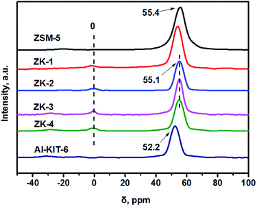
27Al MAS NMR was carried out to investigate the coordination of Al atoms in the as-synthesized ZK series supports. As shown in Fig. 5, the sharp peak at about 55 ppm was due to tetrahedrally coordinated Al atoms in the zeolite framework,35 while the weak peak at 0 ppm could be assigned to extra-framework aluminum with octahedrally coordinated (AlO6 structural unit). Zeolite ZSM-5 only showed one peak at 55.4 ppm, illustrating that all the Al atoms were in main framework. A similar phenomenon was observed for the ZK series supports, which exhibited an intense peak at about 55.1 ppm rather than 52.2 ppm as Al-KIT-6 (a kind of aluminosilicate) after the incorporation of Al atoms into KIT-6.26 The results prove the Al coordinations in ZK materials are the same as that in zeolite ZSM-5, indicating that the mesoporous framework of ZK is assembled by zeolite ZSM-5 primary and secondary building units.3.4. TEM results
Some typical TEM images of the as-synthesized materials are exhibited in Fig. 6. The ZSM-5 particles show a good dispersion and possess a uniform particle size of ∼150 nm.29 The representative images of KIT-6 and ZK materials exhibit well-regulated arrays of mesoporous channels. No obvious ZSM-5 particles could be observed in the TEM images of the ZK samples, indicating that no ZSM-5 particle was formed in the ZK composites. From Fig. 6, it can be seen that ZK-1 and ZK-4 exhibit well-ordered hexagonal mesopores with a p6mm hexagonal structure, while ZK-2 and ZK-3 show a cubic Ia![[3 with combining macron]](https://www.rsc.org/images/entities/char_0033_0304.gif) d mesoporous structure similar to KIT-6.16,22 The images show that the structure of the as-synthesized composites depends on the addition amount of BuOH. A high or low molar ratio of BuOH/P123 (BuOH/P123 = 120 or 80) leads to the formation of a hexagonal cylindrical porous structure. The TEM images agree well with the XRD results.
d mesoporous structure similar to KIT-6.16,22 The images show that the structure of the as-synthesized composites depends on the addition amount of BuOH. A high or low molar ratio of BuOH/P123 (BuOH/P123 = 120 or 80) leads to the formation of a hexagonal cylindrical porous structure. The TEM images agree well with the XRD results.
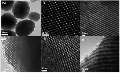 | ||
| Fig. 6 Typical TEM images of the as-synthesized materials: (A) ZSM-5, (B) KIT-6, (C) ZK-1,(D) ZK-2, (E) ZK-3, (F) ZK-4. | ||
3.5. N2 adsorption–desorption results
As mentioned above, the amount of n-butanol has a significant effect on the pore properties of the synthesized materials. Therefore, the series of ZK materials were characterized by N2 adsorption–desorption. The N2 adsorption–desorption isotherms of the as-synthesized materials are displayed in Fig. 7. Both the KIT-6 and ZK supports exhibited type-IV isotherms with H1-type hysteresis loops, which are typical behaviors of ordered mesoporous structures.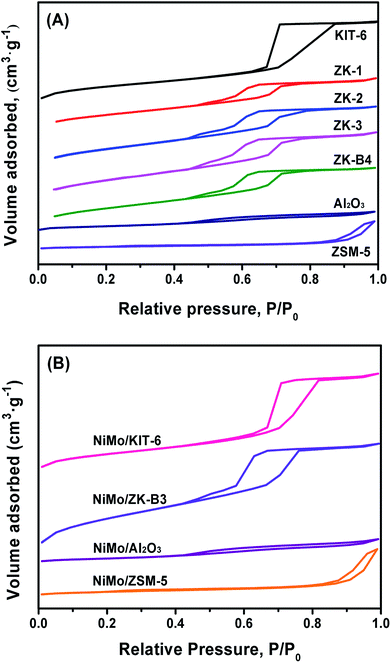 | ||
| Fig. 7 N2 adsorption–desorption isotherms of the as-synthesized materials (A) and corresponding catalysts (B). | ||
However, compared with KIT-6, the “relative heights” of the hysteresis loops of ZK materials were lower due to the reduction of pore volume, which was caused by the assembly of ZSM-5 zeolite seeds. Al2O3 also exhibited a type-IV isotherm with a H4-type hysteresis loop, which could be attributed to the intergranular pores. Zeolite ZSM-5 exhibited a type-I isotherm of a microporous material with a small loop at a high relative pressure due to the adsorption of intergranular pores between the nano-sized particles.
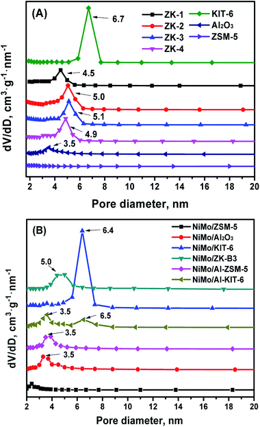
The pore size distribution (PSD) curves of the different supports are shown in Fig. 8. The KIT-6, ZK composites, and Al2O3 supports show a narrow PSD, with mesoporous silica KIT-6 possessing the largest average pore size. The micro–mesoporous ZK materials exhibited a little smaller pore size than KIT-6, on one hand, this was likely because the ZSM-5 primary and secondary structure were assembled in to a mesoporous wall, which thickens the pore wall and decreases the pore size. On the other hand, this phenomenon can be explained by the pore plugging inside mesoporous channels due to the assembly of some non-uniform-sized nanocrystals of zeolite ZSM-5. Different molar ratios of BuOH/P123 could also affect the PSD of this series of materials. The Al2O3 support had a PSD with an average pore diameter of 3.5 nm, but nevertheless, the ZSM-5 zeolite showed a wider PSD, and no mesoporous channels were discovered.
The isotherms of all the catalysts were similar to their corresponding supports, while the relative heights of the hysteresis loops were decreased slightly due to the impregnation of active metals. The PSD curves display no obvious changes in average pore size, which demonstrates that the mesoporous structures were reserved after the loading of NiMo species.
The textural properties of the as-synthesized materials and their corresponding catalysts are shown in Table 1. KIT-6 possessed the largest specific area (929 m2 g−1), pore volume (1.04 cm3 g−1), and average pore diameter (6.9 nm). The textural properties of ZK materials showed a decreasing tendency, but these were still more superior to ZSM-5 zeolite. The sample ZK-3 displayed the highest specific area (858 m2 g−1), largest pore volume (0.90 cm3 g−1), and an average pore diameter (4.6 nm), resulting from the difference in the amount of n-butanol. It's known that the addition of n-butanol has a significant effect on the phase area of the synthesized material, thus a suitable addition of n-butanol is beneficial to form a cubic Ia![[3 with combining macron]](https://www.rsc.org/images/entities/char_0033_0304.gif) d structure. The results indicated that the synthesized ZK material had the best pore structure. Because of the channel blockage of NiMo species in the impregnation process, the specific surface area and pore volume of all the catalysts were clearly decreased in comparison with their corresponding supports. Fortunately, the mesoporous structures were not destroyed, which would not affect too much the mass transfer ability.
d structure. The results indicated that the synthesized ZK material had the best pore structure. Because of the channel blockage of NiMo species in the impregnation process, the specific surface area and pore volume of all the catalysts were clearly decreased in comparison with their corresponding supports. Fortunately, the mesoporous structures were not destroyed, which would not affect too much the mass transfer ability.
| Samples | SBETa (m2 g−1) | Vtb (cm3 g−1) | Vmesc (cm3 g−1) | dBJHd (nm) |
|---|---|---|---|---|
| a Calculated by the BET method.b The total pore volume was obtained at a relative pressure of 0.98.c Calculated using the BJH method.d Mesopore diameter calculated by the BJH method. | ||||
| Al2O3 | 169 | 0.24 | 0.23 | 3.5 |
| ZSM-5 | 304 | 0.43 | — | — |
| KIT-6 | 929 | 1.04 | 0.96 | 6.9 |
| ZK-1 | 693 | 0.75 | 0.67 | 4.3 |
| ZK-2 | 811 | 0.86 | 0.76 | 4.5 |
| ZK-3 | 858 | 0.90 | 0.82 | 4.6 |
| ZK-4 | 720 | 0.83 | 0.74 | 4.3 |
| NiMo/Al2O3 | 112 | 0.18 | 0.18 | 3.4 |
| NiMo/ZSM-5 | 195 | 0.32 | — | — |
| NiMo/KIT-6 | 470 | 0.77 | 0.72 | 5.9 |
| NiMo/ZK-3 | 437 | 0.52 | 0.47 | 4.2 |
| NiMo/Al-ZSM-5 | 139 | 0.18 | 0.18 | — |
| NiMo/Al-KIT-6 | 151 | 0.26 | 0.26 | 4.0 |
| NiMo/Al-ZK-3 | 151 | 0.22 | 0.22 | 3.5 |
3.6. Pyridine-FTIR results
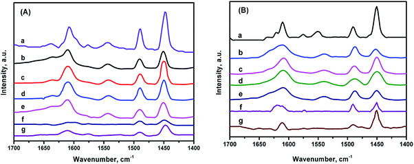
Fig. 9 shows the FTIR spectra of the different catalysts after pyridine adsorption in the region of 1700–1400 cm−1.The peaks appearing at 1540 cm−1 and 1450 cm−1 could be designated as Brønsted and Lewis acid sites, respectively. The peak around 1490 cm−1 stands for the pyridine co-adsorption of both Brønsted and Lewis acid, meanwhile, the band located around 1610 cm−1 belongs to a Lewis acid.3,36,37 The amounts of Lewis and Brønsted acid sites on the different catalysts are listed in Table 2. The NiMo/ZSM-5 owns the largest amounts of acid sites among all the catalysts. NiMo/KIT-6 showed a much lower strength of acid, just slightly higher than NiMo/Al2O3 because of the electroneutral framework of KIT-6. No Brønsted acids were detected over NiMo/KIT-6 and NiMo/Al2O3. The composite material ZK combines the advantages of ZSM-5 and KIT-6, so the NiMo catalysts supported on ZK retained the Brønsted acid sites, which enhanced the acidity of the material compared with the NiMo catalyst supported on pure KIT-6. The total acid amounts decrease in the order: NiMo/ZSM-5 > NiMo/ZK-2 > NiMo/ZK-3 > NiMo/ZK-1 > NiMo/ZK-4 > NiMo/Al2O3 > NiMo/KIT-6. The B/L ratios of the total acid and the medium and strong acid of the ZK-supported catalysts follow the order: NiMo/ZK-3 (0.24, 0.25) > NiMo/ZK-2 (0.21, 0.22) > NiMo/ZK-1 (0.19, 0.22) > NiMo/ZK-4 (0.18, 0.21), demonstrating that the incorporation of ZSM-5 structural units into the porous wall of KIT-6 is beneficial for the formation of B acid sites. Meanwhile, Al atoms all existed in the ZSM-5 structural units, with the results also indicating that the Al atoms were embedded in the porous framework, which is in accordance with the 27Al MAS NMR results.
| Catalysts | 473 K (μmol g−1) | 623 K (μmol g−1) | B/L | |||||
|---|---|---|---|---|---|---|---|---|
| L | B | L + B | B/L | L | B | L + B | ||
| NiMo/Al2O3 | 92 | — | 92 | 0 | 39 | — | 39 | 0 |
| NiMo/ZSM-5 | 342 | 89 | 431 | 88 | 21 | 109 | ||
| NiMo/KIT-6 | 43 | — | 43 | 0 | 37 | — | 37 | 0 |
| NiMo/ZK-1 | 129 | 25 | 154 | 0.19 | 46 | 10 | 56 | 0.22 |
| NiMo/ZK-2 | 140 | 30 | 170 | 0.21 | 51 | 11 | 62 | 0.22 |
| NiMo/ZK-3 | 135 | 32 | 167 | 0.24 | 53 | 13 | 66 | 0.25 |
| NiMo/ZK-4 | 125 | 23 | 148 | 0.18 | 42 | 9 | 51 | 0.21 |
3.7. H2-TPR results
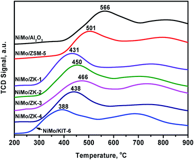
H2-TPR curves of different catalysts are exhibited in Fig. 10. The profiles of all the catalysts exhibited two reduction peaks in the ranges of 380–570 °C and 650–850 °C. The former peak could be attributed to the reduction of octahedral Mo species (Mo6+ + 2e− → Mo4+).38 The high-temperature reduction peak was due to the complete reduction of Mo4+ species (Mo4+ + 2e− → Mo0).38 The temperatures of different peaks strongly depend on the metal–support interaction force (MSI). The weaker the metal–support interaction force, the lower is the reduction temperature.It can be seen from Fig. 10 that NiMo/Al2O3 possessed the strongest MSI with a reduction temperature of 566 °C, while NiMo/KIT-6 possessed the weakest, with a reduction temperature of 388 °C. The first reduction temperatures follow the order: NiMo/Al2O3 (566 °C) > NiMo/ZSM-5 (501 °C) > NiMo/ZK-3 (466 °C) > NiMo/ZK-2 (450 °C) > NiMo/ZK-4 (438 °C) > NiMo/ZK-1 (431 °C) > NiMo/KIT-6 (388 °C), demonstrating that the MSIs of the NiMo/ZK catalysts had a proper MSI in comparison to NiMo/Al2O3, NiMo/ZSM-5 and NiMo/KIT-6.
3.8. Raman results
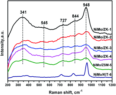
Raman spectroscopy is a very effective method to evaluate the dispersion of active components on supports.39 The Raman spectra are shown in Fig. 11 for all the supported NiMo catalysts, where five unambiguous peaks can be recognized. These catalysts show obvious peaks around 948 cm−1 and 844 cm−1, which could be assigned to the NiMoO4 precursor phase.38,40 The band at 948 cm−1 belongs to the symmetric and asymmetric Mo![[double bond, length as m-dash]](https://www.rsc.org/images/entities/char_e001.gif) O terminal stretching vibrations of various surface polymolybdate species, indicating highly dispersed octahedral Mo6+ surface species, which come from Mo7O246− species.41 These molybdenum oxide species are deemed to have a weak interaction between supports and active metals, thus contributing to their higher reducibility in HDS reactions.38 The intensities of bands around 948 cm−1 follow the sequence: NiMo/ZK-1 > NiMo/ZK-4 > NiMo/ZK-2 > NiMo/ZK-3, which demonstrates that the MSIs decrease in the inverse order. NiMo/ZK-1 possessed the similar MSIs as NiMo/KIT-6, which was too weak, while the MSIs of NiMo/ZK-2, NiMo/ZK-3, and NiMo/ZK-4 catalyst were promoted. These result agree well with the H2-TPR results. The band at 844 cm−1 could be ascribed to the asymmetric stretching mode of the Mo–O–Mo bridge bond of the octahedral molybdate species.41 The bands at 727 cm−1 could be attributed to the α-NiMoO4 phase.42 The vibration band at 545 cm−1 results from the stretching model of Al–O (Mo–O–Al).43 The broad peak at 341 cm−1 represents the bending model of terminal Mo
O terminal stretching vibrations of various surface polymolybdate species, indicating highly dispersed octahedral Mo6+ surface species, which come from Mo7O246− species.41 These molybdenum oxide species are deemed to have a weak interaction between supports and active metals, thus contributing to their higher reducibility in HDS reactions.38 The intensities of bands around 948 cm−1 follow the sequence: NiMo/ZK-1 > NiMo/ZK-4 > NiMo/ZK-2 > NiMo/ZK-3, which demonstrates that the MSIs decrease in the inverse order. NiMo/ZK-1 possessed the similar MSIs as NiMo/KIT-6, which was too weak, while the MSIs of NiMo/ZK-2, NiMo/ZK-3, and NiMo/ZK-4 catalyst were promoted. These result agree well with the H2-TPR results. The band at 844 cm−1 could be ascribed to the asymmetric stretching mode of the Mo–O–Mo bridge bond of the octahedral molybdate species.41 The bands at 727 cm−1 could be attributed to the α-NiMoO4 phase.42 The vibration band at 545 cm−1 results from the stretching model of Al–O (Mo–O–Al).43 The broad peak at 341 cm−1 represents the bending model of terminal Mo![[double bond, length as m-dash]](https://www.rsc.org/images/entities/char_e001.gif) O of octahedral MoO42− species.44
O of octahedral MoO42− species.44
3.9. HRTEM results
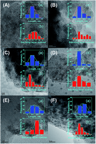
It is commonly accepted that the activities of catalysts are greatly related to the state of MoS2 distribution on the supports.45 To date, HRTEM characterization has been considered a relatively impactful measurement, and enables to obtain the lengths and stacking degree of MoS2 crystallites over the catalysts.46 The representative HRTEM micrographs are displayed in Fig. 12. The average length Lav and stacking layer number Nav of the MoS2 crystallites were calculated based on eqn (1):27
 | (1) |
The dispersion degree of Mo (fMo) was calculated from eqn (2):27
 | (2) |
The textural properties are closely related to the dispersion and sulfuration degree of the active phases. Different specific surface areas and pore structures would lead to the formation of a different morphology of NiMoS crystallite, which would have a significant influence on the catalytic performance.47 It has been reported that the Ni–Mo–S active phase has two different types of structure, resulting in a notable difference in reaction activity.48,49 The structure with low intrinsic activity is designate as type-I Ni–Mo–S phase, while the type-II Ni–Mo–S phase has an improved intrinsic activity, which favors HDS reaction processes.50 A short length and appropriate stacking degree of NiMoS slabs are helpful to form the type-II Ni–Mo–S active phase.51 The NiMo/ZSM-5 catalyst with the lowest stacking degree of NiMoS slab would form more type-I Ni–Mo–S phase, and hence NiMo/ZSM-5 displays the lowest HDS activity. The NiMo/KIT-6 catalyst with the highest stacking degree of NiMoS crystallites could form more type-II active phases, which is beneficial for HDS reactions, but its Lav is not short. NiMo/ZK catalysts possess a more appropriate stacking degree and a shorter average length of NiMoS slabs compared with the catalysts NiMo/KIT-6 and NiMo/ZSM-5. A lower degree of stacking layer number of NiMoS restricts the planar adsorption of the reactants, therefore inhibiting the catalytic performances of catalysts.52,53 However, it must be noted that only the external staking layer of NiMoS would reveal particular edge sites. If the stacking number is overtopped, the amount of corner and edge sites would decrease.
The statistical results Lav and Nav of the different catalysts are shown in Table 3. The dispersion degrees of active sites (fMo) show the trend: NiMo/ZK-3 > NiMo/ZK-2 > NiMo/ZK-4 > NiMo/ZK-1 > NiMo/ZSM-5 > NiMo/KIT-6. The results are due to the combined effects between the pore structure properties and metal–support interaction forces. The open pore structure favors the diffusion of active species to promote the sulfide degree of active metals, while a suitable metal–support interaction can be propitious to the diffusion of active species. However, if the metal–support interaction is too strong, Ni ions can form spinel structures with Al2O3, which affects the dispersion and sulfuration of active components. The superior pore structure of micro–mesoporous composite materials and appropriate metal–support interaction in the catalysts, such as NiMo/ZK-3, enable a better diffusion of NiMoS crystallites than NiMo supported on pure ZSM-5 and KIT-6. Overall, the NiMo/ZK-3 catalyst had a better NiMoS dispersion and possessed more active edge sites, which were favorable for HDS processes.
| Catalyst | Lav (nm) | Nav | fMo |
|---|---|---|---|
| NiMo/ZK-1 | 3.94 | 3.45 | 0.33 |
| NiMo/ZK-2 | 3.62 | 3.19 | 0.37 |
| NiMo/ZK-3 | 3.18 | 3.36 | 0.42 |
| NiMo/ZK-4 | 3.79 | 3.24 | 0.34 |
| NiMo/ZSM-5 | 4.92 | 3.06 | 0.28 |
| NiMo/KIT-6 | 5.02 | 3.50 | 0.27 |
3.10. Catalyst evaluation
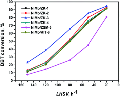
It can be seen that the conversion of DBT clearly increases as the LHSV decreases. Almost all the composite-supported catalysts exhibited better HDS performances than the catalysts supported on pure ZSM-5 and KIT-6. The catalytic activities of these catalysts kept to the order: NiMo/ZK-3 > NiMo/ZK-2 > NiMo/ZK-4 > NiMo/ZK-1 > NiMo/KIT-6 > NiMo/ZSM-5. The DBT conversion of NiMo/ZK-3 at LHSV = 150 h−1, which was about twice that of NiMo/KIT-6 and more than three times that of NiMo/ZSM-5. This is because the addition of n-butanol changes the texture properties of ZK composites. The addition of n-butanol changes the pore diameter and pore volume, which directly affect the ability of diffusion, resulting in the differences in the distribution of the active metal phase. NiMo/ZK-3 with the largest specific area, pore volume, and pore diameter exhibited the highest DBT conversion among this series of catalysts.
To clarify the effect of the amount of n-butanol on the reaction pathways of DBT, the reaction samples over different catalysts with a total DBT conversion of around 50% were analyzed by GC-MS chromatography. The products distributions are shown in Table 4. Five products: tetrahydro-dibenzothiophene (THDBT), cyclohexen-1-ylbenzene (CHEB), phenylcyclohexane (CHB), biphenyl (BP), and iso-phenyl-hexadiene (Iso-PHDi) were detected over the series of NiMo/ZK catalysts, similar to the DBT HDS products over NiMo/BK catalysts reported by Zhang et al.26 Since no Brønsted acid sites exist in the NiMo/KIT-6 catalyst, the isomerization products were not found in the HDS products of the NiMo/KIT-6 catalyst, as shown in Table 4. BP is the final product of the DDS pathway, and the DDS pathway is the primary route for the HDS of DBT. THDBT, CHEB, and CHB are sequentially generated in the HYD pathway,54,55 and a part of Iso-PHDi was formed from CHEB under the isomerization of the Brønsted acid. CHB accounts for the largest proportion of the products of the HYD pathway. The BP selectivities of the series of catalysts follow the order: NiMo/ZK-3 (72.1%) > NiMo/ZK-2 (65.1%) > NiMo/ZK-4 (62.2%) > NiMo/ZK-1 (60.5%). NiMo/ZK-3 exhibited the highest DBT HDS activity. The higher catalytic performance and selectivity of the DDS route could be attributed to the superior pore properties of the supports.
| Catalysts | Product selectivity (%) | HYD/DDS ratioa (%) | ||||
|---|---|---|---|---|---|---|
| HYD | DDS | |||||
| THDBT | CHEB | CHB | Iso-PHDi | BP | ||
| a Equal to the total selectivities of THDBT, CHEB, CHB, and Iso-PHDi. | ||||||
| NiMo/ZK-1 | 3.6 | 5.1 | 24.5 | 6.3 | 60.5 | 65.3 |
| NiMo/ZK-2 | 2.6 | 5.9 | 19.4 | 7.0 | 65.1 | 53.6 |
| NiMo/ZK-3 | 1.9 | 6.1 | 12.3 | 7.6 | 72.1 | 38.7 |
| NiMo/ZK-4 | 2.8 | 5.6 | 22.9 | 6.5 | 62.2 | 60.8 |
| NiMo/ZSM-5 | 2.6 | 0.6 | 37.1 | 9.4 | 50.3 | 98.8 |
| NiMo/KIT-6 | 4.0 | 6.1 | 32.0 | — | 57.9 | 72.7 |
4. Conclusions
In this research, a novel micro–mesoporous composite material ZK was prepared by assembling ZSM-5 crystals into a well-ordered mesoporous framework. The directional synthesis of micro–mesoporous composites with a controllable modulation of the pore structures was achieved by adjusting the addition amount of n-butanol. The texture properties of the as-synthesized composites with different addition amounts of n-butanol showed obvious differences with the increasing molar ratio of BuOH/P123. A high or low molar ratio of BuOH/P123 (BuOH/P123 = 120 or 80) led to the formation of a hexagonal cylindrical pore structure. When BuOH/P123 = 100, ZK-3 showed the typical cubic Ia![[3 with combining macron]](https://www.rsc.org/images/entities/char_0033_0304.gif) d mesoporous structure, and possessed the largest specific area (858 m2 g−1) and pore volume (0.90 cm3 g−1). The ZK material combined the advantages of KIT-6 and ZSM-5, possessing as large specific area, pore size, and pore volume as KIT-6 silica; moreover, it also had a similar acid distribution and a little weaker acidity of the ZSM-5 zeolite.
d mesoporous structure, and possessed the largest specific area (858 m2 g−1) and pore volume (0.90 cm3 g−1). The ZK material combined the advantages of KIT-6 and ZSM-5, possessing as large specific area, pore size, and pore volume as KIT-6 silica; moreover, it also had a similar acid distribution and a little weaker acidity of the ZSM-5 zeolite.
The NiMo/ZK catalysts were evaluated using DBT and diesel oil as raw materials. The NiMo/ZK-3 catalyst showed the highest catalytic activity in the HDS of DBT. The HDS reaction network of DBT over NiMo/ZK catalysts had two reaction routes: DDS and HYD pathways. The DDS pathway was the main route of the HDS reaction. BP and CHB were the main products of the DDS and HYD pathways, respectively. The molar ratio of BuOH/P123 had an effect on HYD selectivity, whereby when BuOH/P123 = 100, the BP selectivity reached up to 72.1%. Furthermore, the NiMo/AlZK-3 catalyst showed superior catalytic performance in the HDS of diesel oil. ZK-3-supported NiMo catalysts exhibited excellent DBT and diesel HDS performances because of the excellent textural property, moderate MSI, and relatively high B/L ratios of the catalysts, and due to the highly dispersed NiMoS active phases. These results are meaningful for the future applications of industrial HDS catalysts.
Conflicts of interest
There are no conflicts to declare.Acknowledgements
The authors acknowledge the financial supports from the National NSFC (No. 21503152, No. 21276277, No. U1463207), the Natural Science Foundation of Hubei Province (2014CFA090), the Opening Project of the Key Laboratory of Green Chemical Process (Wuhan Institute of Technology) (GCP201401), the Scientific Research Foundation of Wuhan Institute of Technology (K201640 and K201760), and the Graduate Innovation Fund of Wuhan Institute of Technology (No. CX2016085). The authors are grateful to Dr Xilong Wang et al. (China University of Petroleum (Beijing)) for the help in the evaluation of catalysts.References
- S. T. Oyama, H. Y. Zhao and H. J. Freund, et al., J. Catal., 2012, 285, 1–5 CrossRef.
- L. Yang, X. Li and A. Wang, et al., J. Catal., 2015, 330, 330–343 CrossRef.
- S. Shan, P. Yuan and W. Han, et al., J. Catal., 2015, 330, 288–301 CrossRef.
- J. Xiong, W. S. Zhu and H. P. Li, et al., Green Chem., 2008, 10, 641–646 RSC.
- J. Xiong, W. S. Zhu and H. M. Li, et al., AIChE J., 2013, 59, 4696–4704 CrossRef.
- M. Ali and S. Natalia, Catal. Sci. Technol., 2018, 8, 2323–2332 RSC.
- Y. Okamoto, M. Breysse and G. M. Muralidhar, et al., Catal. Today, 2003, 86, 1 CrossRef.
- W. Fu, L. Zhang and T. Tang, et al., J. Am. Chem. Soc., 2011, 133, 15346–15349 CrossRef PubMed.
- H. Liu, Y. P. Li and C. L. Yin, et al., Appl. Catal., B, 2016, 198, 493–507 CrossRef.
- H. Wu, A. Duan and Z. Zhao, et al., RSC Adv., 2017, 7, 44340–44347 RSC.
- D. Z. Han, X. Li and L. Zhang, Microporous Mesoporous Mater., 2012, 158, 1–6 CrossRef.
- H. Zhang, L. Han and A. Duan, et al., RSC Adv., 2017, 7, 28038–28047 RSC.
- P. Schacht, S. Ramírez and J. Ancheyta, Energy Fuels, 2009, 23, 4860–4865 CrossRef.
- F. X. Chen, L. Huang and X. J. Yang, et al., Mater. Lett., 2013, 109, 299–301 CrossRef.
- F. Jin, S. J. Huang and S. F. Cheng, et al., Catal. Sci. Technol., 2015, 5, 3007–3016 RSC.
- D. Y. Zhao, J. L. Feng and B. . F. Chmelka, et al., Science, 1998, 279, 548–552 CrossRef PubMed.
- J. Liu, L. Yu and Z. Zhao, et al., J. Catal., 2012, 285, 134–144 CrossRef.
- O. Y. Gutiérrez, F. Pérez and G. A. Fuentes, et al., Catal. Today, 2008, 130, 292–301 CrossRef.
- S. F. Chen, J. L. Li and Y. H. Zhang, et al., Catal. Sci. Technol., 2014, 4, 1005–1011 RSC.
- S. F. Chen, J. L. Li and Y. J. Zhang, et al., Top. Catal., 2014, 57, 437–444 CrossRef.
- F. He, J. Q. Luo and S. T. Liu, et al., Chem. Eng. J., 2016, 294, 362–370 CrossRef.
- T. W. Kim and F. Kleitz, et al., J. Am. Chem. Soc., 2005, 127, 7601–7610 CrossRef PubMed.
- M. Choi, K. Na and J. Kim, et al., Nature, 2009, 461, 246–249 CrossRef PubMed.
- K. Soni, B. S. Rana and A. K. Sinha, et al., Appl. Catal., B, 2009, 90, 55–63 CrossRef.
- Q. Y. Yu, L. Zhang and R. Guo, Fuel Process. Technol., 2017, 159, 76 CrossRef.
- D. Zhang, A. Duan and Z. Zhao, et al., J. Catal., 2010, 274, 273–286 CrossRef.
- A. J. Duan, T. S. Li and Z. Zhao, et al., Appl. Catal., B, 2015, 165, 763–773 CrossRef.
- Q. Y. Yu, L. Zhang and R. Guo, et al., Fuel Process. Technol., 2017, 159, 76–87 CrossRef.
- H. D. Wu, A. J. Duan and Z. Zhao, et al., J. Catal., 2014, 317, 303–317 CrossRef.
- R. V. Grieken, J. L. Sotelo and J. M. Menéndez, et al., Microporous Mesoporous Mater., 2000, 39, 135–147 CrossRef.
- F. Kleitz, S. H. Choi and R. Ryoo, Chem. Commun., 2003, 9, 2136–2137 RSC.
- Y. Wan and D. Y. Zhao, Chem. Rev., 2007, 107, 2821–2860 CrossRef PubMed.
- V. Umamaheswari, M. Palanichamy and V. Murugesan, J. Catal., 2002, 210, 367–374 CrossRef.
- Y. Liu, W. Z. Zhang and T. J. Pinnavaia, et al., Angew. Chem., Int. Ed., 2001, 40, 1255–1257 CrossRef PubMed.
- E. Lippmaa, A. Samoson and M. Magi, J. Am. Chem. Soc., 1986, 108, 1730 CrossRef.
- J. A. Z. Pieterse, S. V. Reyes and L. Domokos, et al., J. Catal., 1999, 187, 518–520 CrossRef.
- M. Maache, A. Janin and J. C. Lavalley, et al., Zeolites, 1993, 13, 419–426 CrossRef.
- R. L. Cordero, F. G. Llambias and A. L. Agudo, Appl. Catal., 2000, 74, 125–136 CrossRef.
- W. Li, G. D. Meitzner and E. Lglesia, J. Catal., 2000, 191, 373–383 CrossRef.
- P. Biswas, P. Narayanasarma and A. K. Dalai, et al., Ind. Eng. Chem. Res., 2011, 50, 7882–7895 CrossRef.
- H. Hu, I. E. Wachs and S. R. Bare, J. Phys. Chem. C, 1995, 99, 10897–10910 CrossRef.
- Y. Wang, G. Xiong and X. Liu, et al., J. Phys. Chem. C, 2008, 112, 17265–17271 CrossRef.
- W. Han, P. Yuan and Y. Fan, et al., J. Mater. Chem., 2012, 22, 25340–25353 RSC.
- X. Wang, Z. Zhao and P. Zheng, et al., J. Catal., 2016, 344, 680–691 CrossRef.
- T. E. Klimova, D. Valencia and J. A. Mendoza-Nieto, J. Catal., 2013, 304, 29–46 CrossRef.
- D. Valencia and T. Klimova, Appl. Catal., B, 2013, 129, 137–145 CrossRef.
- O. Y. Gutieérrez, S. Singh and J. A. Lercher, et al., ACS Catal., 2014, 4, 1487–1499 CrossRef.
- S. Kasztelan, H. Toulhoat and J. Grimblot, et al., Appl. Catal., 1984, 13, 127–135 CrossRef.
- H. Topsøe, Appl. Catal., A, 2007, 322, 3–8 CrossRef.
- D. Gao, A. Duan and X. Zhang, et al., Appl. Catal., B, 2015, 165, 269–284 CrossRef.
- Y. Li, D. Pan and C. Xu, et al., J. Catal., 2012, 286, 124–136 CrossRef.
- F. Besenbacher, M. Brorson and J. Kibsgaard, et al., Catal. Today, 2008, 130, 86–96 CrossRef.
- O. Gutiérrez and T. J. Klimova, Catalysis, 2011, 281, 50–62 CrossRef.
- E. Marina and P. Roel, J. Catal., 2004, 225, 417–427 CrossRef.
- Y. Y. Sun and P. Roel, J. Catal., 2009, 267, 193–201 CrossRef.
Footnote |
| † This author has equal contribution as the first author. |
| This journal is © The Royal Society of Chemistry 2018 |

