
 Open Access Article
 This Open Access Article is licensed under a Creative Commons Attribution-Non Commercial 3.0 Unported Licence
Hexagonal hollow silica plate particles with high transmittance under ultraviolet-visible light†
Lailatul Qomariyah a,
Aditya F. Arifb,
W. Widiyastutia,
Sugeng Winardia,
Shuto Taniguchib and
Takashi Ogi*b
a,
Aditya F. Arifb,
W. Widiyastutia,
Sugeng Winardia,
Shuto Taniguchib and
Takashi Ogi*b
aDepartment of Chemical Engineering, Faculty of Industrial Technology, Institut Teknologi Sepuluh Nopember, Kampus ITS Sukolilo, Surabaya 60111, Indonesia
bDepartment of Chemical Engineering, Graduate School of Engineering, Hiroshima University, 1-4-1 Kagamiyama, Higashi-Hiroshima, Hiroshima 739-8527, Japan. E-mail: ogit@hiroshima-u.ac.jp
First published on 23rd July 2018
Abstract
Creating hollow structures is one strategy for tuning the optical properties of materials. The current study aimed to increase the optical transmittance of silica (SiO2) particles. To this end, hexagonal-shaped hollow silica plate (HHSP) particles were synthesized from tetraethyl orthosilicate (TEOS) and zinc oxide (ZnO) template particles, using a microwave-assisted hydrothermal method. The size and shell thickness of the HHSP particles could be adjusted by using different TEOS/ZnO molar ratios and different ZnO template sizes, respectively. The optical transmittance of the HHSP particles depended on the shell thickness and particle size. The highest transmittance was 99% in the ultraviolet and visible region (300–800 nm) and was exhibited by HHSP particles with the thinnest shell thickness of 6.3 nm. This transmittance was higher than that exhibited by spherical hollow silica particles with a similar shell thickness. This suggested morphology-dependent transmittance for the semiconducting material. These preliminary results illustrate the promising features of the HHSP particles and suggest their potential application in future transparent devices.
1. Introduction
Hollow inorganic materials have attracted much interest in recent decades, due to their innovative structures and potential applications. The cavities inside such structures generally provide a large surface area1–5 and low bulk density, resulting in materials with high surface area per weight ratios. In some semiconductor materials, the cavities result in additional features such as low thermal conductivity6 and enhanced optical properties.7–10 The later properties are the motivation for developing structured semiconductors, such as hollow-structured silica (SiO2), for optical devices.Research on the structuring of hollow SiO2 has largely focused on creating spherical shapes. Several studies have reported monodisperse hollow SiO2 spheres with high transmittance. In general, the amount of light transmitted through a particle depends on the amount of reflection and absorption occurring along the light path.11 The transmittance is related to the surface plasmon resonance caused by the electron oscillation. For metallic materials in particular, the oscillation-induced plasmon band is affected by the axis length along which the oscillation takes place.11 Previous studies have suggested that this characteristic also applies to SiO2, despite it being a semiconductor. These studies reported that higher transmittance was exhibited by hollow SiO2 spheres with smaller cavities and thinner shells.12 A polarization-dependent response due to the aspect ratio was proposed by Gans theory.11 However, such a response provides the opportunity to adjust the optical properties of SiO2 as semiconductor material by tuning the geometry, for example, by creating an anisotropic hollow structure. Many anisotropic structures have been synthesized including nanorods,13–15 nanotubes,16–18 and nanocages.1,19,20 However, this concept has not been well studied in regard to understand the effect of anisotropic structure on the optical properties of semiconductor material such as SiO2.
In this study, we prepared anisotropic hexagonal hollow silica plate (HHSP) particles with high transmittance under ultraviolet (UV) and visible (Vis) light. The HHSP particles were synthesized from tetraethyl orthosilicate (TEOS) using a rapid, surfactant-free synthesis involving microwave irradiation. The microwave irradiation accelerated the hydrolysis and condensation of TEOS on the template surface. The hollow structure was formed using zinc oxide (ZnO) particles as the template, which were easily removed by etching using low-concentration acidic solution. The shell thickness of the HHSP particles could be adjusted by changing the TEOS concentration, which also affected the optical transmittance of the HHSP particles. We compared the optical transmittance of hexagonal hollow structure with spherical hollow structure to study the effect of anisotropic structure on its optical properties.
2. Materials and methods
In a typical synthesis of the HHSP particles, ZnO template particles (Sakai Chemical Industry, Co. Ltd., Osaka, Japan) were well dispersed in ethanol by ultrasonicating for 30 min. Ultrapure water, TEOS (99.9%, Sigma-Aldrich, St. Louis, MO, USA), and ammonia solution (Kanto Chemical Co., Inc., Tokyo, Japan) were then added to the ZnO dispersion. The resulting mixture was heated under microwave irradiation (Biotage, Uppsala, Sweden) for 1 h at 80 °C. The resulting particles were separated from the solution by centrifugation at 8000 rpm for 10 min, followed by washing and vacuum drying. Removal of ZnO was achieved by etching in 0.2 M hydrochloric acid. Complete etching was indicated by a change in the solution colour from milky to semi-transparent. To control the HHSP particle size and shell thickness, the ZnO size and TEOS/ZnO molar ratio were varied from 0.1 μm to 2 μm and from 0.2 to 1.125, respectively. Four types of ZnO particles were used as templates, as described in detail in Table 1.| ZnO template type | ζ-potential [mV] | Size [μm] | Plate thickness [nm] |
|---|---|---|---|
| A | +14 | 0.1 | 30 |
| B | −21 | 0.3 | 80 |
| C | −21 | 1.0 | 290 |
| D | −22 | 2.1 | 750 |
The morphologies of the ZnO template particles, ZnO–SiO2 core–shell particles, and HHSP particles were examined using field-emission scanning electron microscopy (SEM; S-5000, 20 kV, Hitachi High-Tech. Corp., Tokyo, Japan) and transmission electron microscopy (TEM; JEM-2010, 200 kV, JEOL Ltd., Tokyo, Japan).
The shell thickness and particle size were measured from approximately 200 randomly selected particles observed in the TEM images and SEM images, respectively. The ζ-potentials were determined by dynamic light scattering (DLS; Zetasizer Nano ZSP, Malvern Instruments Ltd., Malvern, U.K.). The measurement of optical transmittance was performed using UV-Vis spectroscopy (UV-3150; Shimadzu Corp., Japan). Fourier-transform infrared (FT-IR) spectra were recorded to investigate the chemical bonding in the particles (IRAffinity-1S; Shimadzu Corp., Japan).
3. Results and discussion
The formation of the HHSP particles, as illustrated in Fig. 1(a), was initiated by the nucleation of negatively charged TEOS (−34 mV) on the ZnO surface. Two different mechanisms could potentially contribute to the nucleation, which are electrostatic interaction and diffusion-controlled heterogeneous nucleation. Electrostatic-driven nucleation was neglected in the current case because nucleation occurred in both negatively and positively charged ZnO, as indicated by the synthesis of HHSP particles using both positively and negatively charged ZnO, as shown in Fig. 2. Thus, the diffusion-controlled nucleation was dominant. This phenomenon can be explained by classical nucleation theory, i.e., heterogenous and homogenous nucleation. Although the current study involved hexagonal-shaped ZnO as the foreign body, the nucleation principle was similar to that in our previous work involving spherical polystyrene latex as the foreign body.21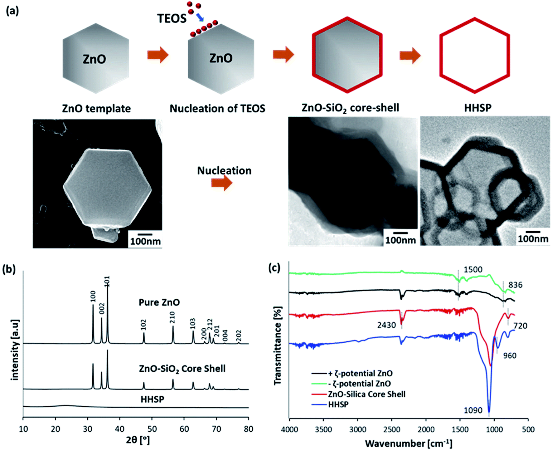 | ||
| Fig. 1 Schematic of the nucleation of SiO2 on the ZnO template (a). XRD patterns of ZnO, ZnO–SiO2 core–shell, and HHSP particles (b). FTIR spectra of ZnO, ZnO–SiO2 core–shell, and HHSP particles (c). | ||
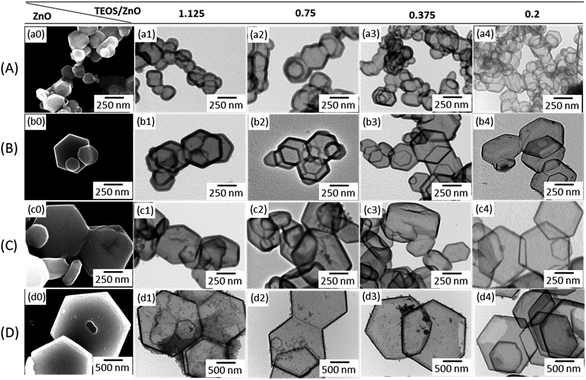 | ||
| Fig. 2 SEM images of the ZnO templates (a0–d0), and TEM images of the respective HHSP particles synthesized using TEOS/ZnO molar ratios of 1.125 (a1–d1), 0.75 (a2–d2), 0.375 (a3–d3), and 0.2 (a4–d4). | ||
After the nucleation of SiO2 on the ZnO surface, TEOS underwent hydrolysis and condensation on the surface of the ZnO template under basic catalytic conditions in the absence of comonomer, to form the silica shell. The formation of the SiO2 shell was confirmed by XRD analysis, the results of which are shown in Fig. 1(b). All peaks in the XRD pattern of the ZnO template could be assigned to the wurtzite structure (Zincite, JCPDS no. 5-0664). The ZnO peaks were also present in the XRD pattern of the ZnO–SiO2 core–shell particles, but with lower intensities. This was consistent with coverage of the ZnO template by amorphous SiO2. FT-IR spectra confirmed the chemical bonding in the ZnO template and ZnO–SiO2 core–shell particles, as shown in Fig. 1(c). The reduction peaks at around 836 cm−1 and 1500 cm−1 were assigned to the vibration of Zn–O bridging bonds.22 These peaks were characteristic peaks of the ZnO template, regardless of the ZnO surface charge. The sharp peak at around 1090 cm−1 confirmed the presence of SiO2, and the peak near 720 cm−1 was assigned to the asymmetric vibration of the Si–O–Si bridging bonds of the siloxane link in the spectrum of the ZnO–SiO2 core–shell particles.23
After removing the ZnO template, the ZnO peak disappeared from the XRD pattern, leaving the peak of amorphous SiO2 at 2θ = 24°. This confirmed that the ZnO template was completely removed from the core, resulting in hexagonal-shaped hollow silica plate particles. The FT-IR spectrum of the etched sample was consistent with this conclusion. The sharp peak corresponding to silica at around 1090 cm−1 remained in the FT-IR spectrum of the etched sample, while the characteristic peak of ZnO was not observed. A new peak was observed near 960 cm−1 which was due to the asymmetric stretching vibration of the Si–OH bridge of the siloxane link.24 Peaks near 2430 cm−1 in the FT-IR spectrum of the etched sample were attributed to hydroxyl groups.22
Fig. 2 shows SEM images of the hexagonal plate ZnO core template particles, and TEM images of HHSP particles synthesized using the respective template. The corresponding SEM images of the HHSP particles are shown in the ESI Fig. S1.† Fig. 2(a0) shows that the type A ZnO template particles existed in an agglomerated state, even after being subjected to ultrasonication. Consequently, HHSP particles synthesized using the type A ZnO template were also agglomerated. The other ZnO templates shown in Fig. 2(b0–d0) were better dispersed after ultrasonication, so yielded more disperse HHSP particles.
The average size and size distribution of the HHSP particles depended on those of the template particles used. As shown in Fig. 3(a), the HHSP particle size increased with increasing ZnO template size. The average HHSP particle size increased from 0.11 μm to 2.1 μm as the ZnO particle size increased from 0.1 μm to 2 μm. The size distributions of the HHSP particles for different template sizes are shown in Fig. S2 (ESI†).
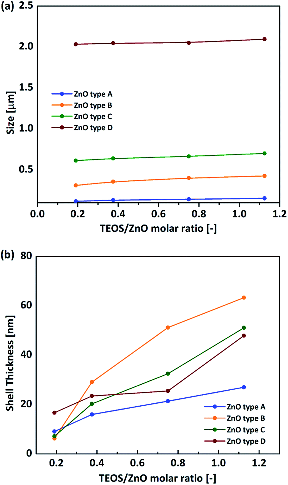 | ||
| Fig. 3 Effect of ZnO template on HHSP size (a) and HHSP shell thickness (b) for different TEOS/ZnO molar ratio. | ||
The HHSP shell thickness could be controlled by tuning the TEOS concentration.25 More SiO2 was formed on the ZnO surface with increasing TEOS concentration, resulting in a thicker shell and hence larger HHSP particles. The HHSP shell thickness increased from 6.3 nm to 63.3 nm as the TEOS/ZnO molar ratio increased from 0.2 to 1.125. The effect of TEOS concentration on the HHSP shell thickness is shown in Fig. 3(b). No solid silica spheres were observed for this TEOS concentration range when using ZnO type A or type B ZnO templates. This implied that the secondary homogenous nucleation of TEOS could be avoided within this range of TEOS/ZnO molar ratios. The importance of the TEOS/ZnO molar ratio for forming hollow structures can be illustrated by the diffusion-controlled nucleation concept. Increasing the TEOS concentration up to supersaturation led to the formation of a hollow structure. Further increasing the TEOS concentration above supersaturation would promote secondary nucleation to form independent dense SiO2 particles.26 A detailed explanation of this is provided in the ESI. The optimum TEOS/ZnO molar ratio was determined to be approximately 1.125, as shown in Fig. S3 (ESI†).
Contrary to the results when using ZnO type A and B templates, independent silica particles were observed in HHSP samples prepared using type C and D ZnO templates, for the same TEOS/ZnO range used for the type A and B templates (Fig. 2(c1, c2 and d1–d4)). This was because the larger template particles had a lower specific surface area, and the driving force for heterogeneous nucleation was proportional to the available surface. Consequently, when a larger ZnO template was used with the same TEOS/ZnO molar ratio, the rate of homogeneous nucleation was higher than the rate of the attachment of TEOS nuclei on the ZnO surface.
The optical transmittances of the various HHSP samples were examined to investigate the effects of shell thickness and particle size on the optical properties. The measurement was conducted in the wavelength range of 300–800 nm using 2 mg ml−1 dispersions of HHSP samples synthesized using type B, type C, and type D ZnO templates. The results are shown in Fig. 4. HHSP samples were synthesized using these three ZnO templates, and the thinnest shells of the resulting HHSP samples were 6.3 nm, 7.2 nm, and 16.7 nm, respectively. The HHSP samples exhibited high transmittances with maximum values of approximately 99%. The transmittance increased with decreasing shell thickness, as less scattered light was absorbed by the thinner shell. All HHSP samples exhibited higher transmittances than that of dense SiO2.
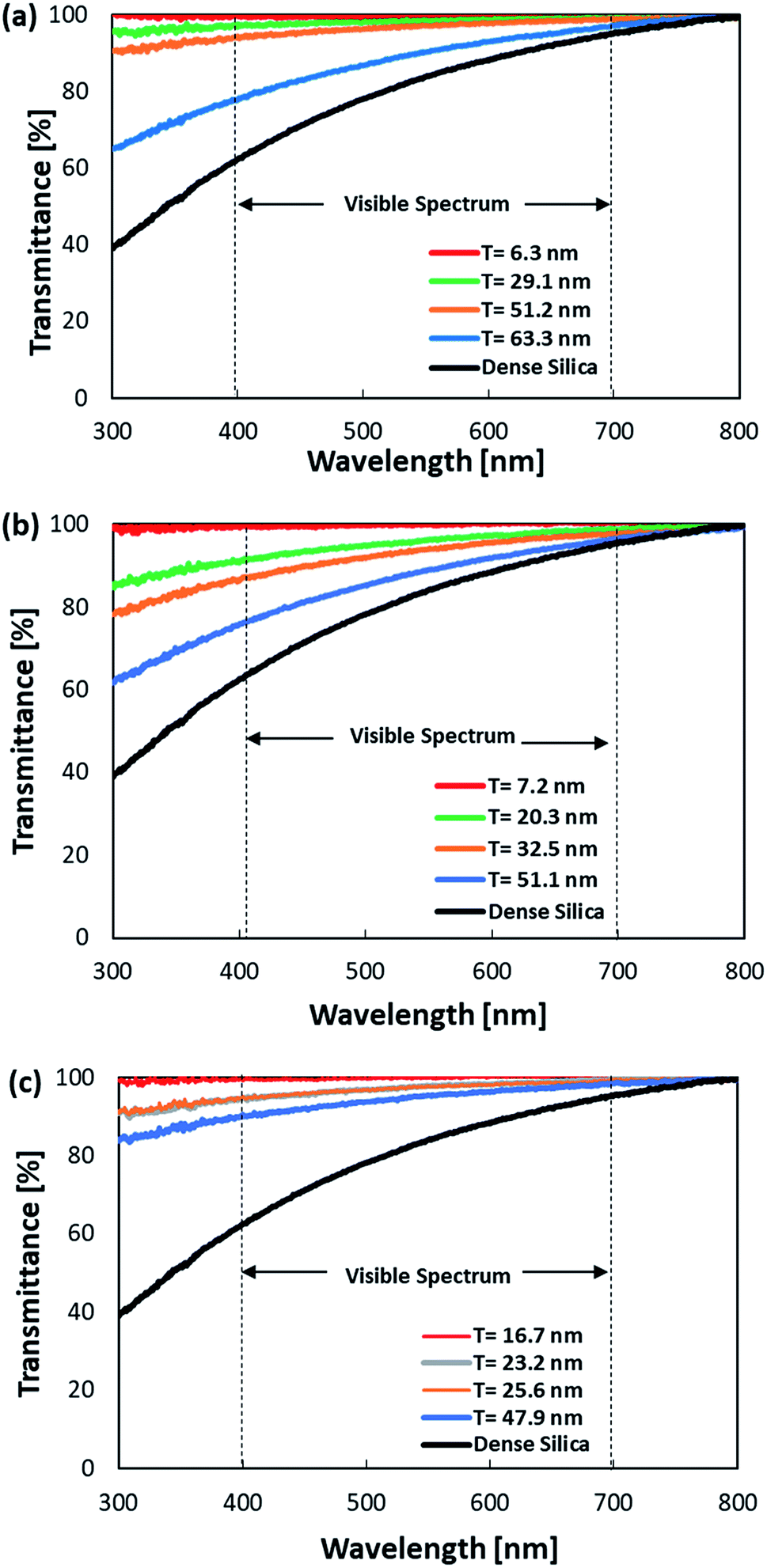 | ||
| Fig. 4 Optical transmittance spectra of HHSP samples with different shell thicknesses prepared from type B (a), type C (b), and type D (c) ZnO templates. | ||
Besides shell thickness, the cavity size also affected the transmittance. For a similar shell thickness (approximately 51 nm), HHSP particles with a smaller cavity (type B) exhibited a higher transmittance than HHSP particles with a larger cavity (type C). The sizes of the HHSP particles were comparable to the wavelength. Thus, the dependence of light scattering behaviour on the shell thickness and cavity size can be explained by the Rayleigh–Gans approximation for backscattering behaviour. This approximation suggests that the cross-sectional backscattering is related to the dimensional element, such as diameter and shell thickness, where a smaller diameter has a lower backscattering.27 Reduced backscattering implies higher transmittance. The thinner shell, coupled with a smaller cavity, led to an increase in the transport of mean free path, which substantially increased the transmittance and reduced backscattering.28
The HHSP particles showed higher transmittances than those of most other hollow morphologies, even with similar shell thicknesses (a detailed comparison is given in Table S1 (ESI†)).6,10,12 As also described by the Rayleigh–Gans approximation, the backscattering behaviour at different wavelengths is affected by the orientation of the optical axis. This is one possible explanation for the differences in the backscattering between isotropic shapes such as spheres and anisotropic shapes such as plates and disks. Correlations between the geometrical anisotropy and optical properties of semiconductors need to be further studied. However, our preliminary results suggest that structuring SiO2 particles into hollow anisotropic structures, such as hollow plates, effectively improves optical transmittance in both the visible and ultraviolet regions. The transmittance characteristics in the visible and ultraviolet range can be adjusted by changing the shell thickness and cavity size. Therefore, the synthesized HHSP particle is a good candidate for future transparent films.
4. Conclusions
In summary, we prepared an anisotropic HHSP structure with high transmittance of ultraviolet and visible light, by microwave irradiation using ZnO as a template. The HHSP particles had a uniform shell thickness. The size and shell thickness could be controlled in the ranges of 6.3–63.3 nm and 0.11–2.1 μm, respectively, by changing the ZnO template size and TEOS concentration. The growth of the shell on the ZnO template involved the classical diffusion-controlled nucleation of TEOS. The template size and TEOS/ZnO molar ratio had a significant role in minimizing homogeneous nucleation. HHSP particles with the thinnest shell exhibited high visible and ultraviolet light transmittance of approximately 99%. This value was higher than that for hollow silica spheres with the same shell thickness. These results indicate the geometrical dependence of the optical properties of semiconductor materials. The HHSP particles with high transmittance have potential as ultra-high transparency films in optical devices.Conflicts of interest
The authors have no conflicts to declare.Acknowledgements
The authors thank the Ministry of Research, Technology, and Higher Education of the Indonesia Government for providing a doctoral scholarship and research grant through the Program Magister Doktor Sarjana Unggul (L. Q.) under Contract No. 128/SP2H/PTNBH/DRPM/2018. This work was supported by JSPS KAKENHI Grant Numbers 26709061 and 16K13642 and was partly supported by the Center for Functional Nano Oxides at Hiroshima University.References
- J. S. Yu, S. B. Yoon, Y. J. Lee and K. B. Yoon, J. Phys. Chem. B, 2005, 109, 7040–7045 CrossRef PubMed.
- S. Machida, T. Yoshida, R. Hashimoto and M. Ogawa, J. Colloid Interface Sci., 2014, 420, 66–69 CrossRef PubMed.
- T. Ogi, A. B. D. Nandiyanto and K. Okuyama, Adv. Powder Technol., 2014, 25, 3–17 CrossRef.
- S. Cao, Z. Zhao, X. Jin, W. Sheng, S. Li, Y. Ge, M. Dong, W. Wu and L. Fang, J. Mater. Chem., 2011, 21, 19124 RSC.
- D. Li, Y. Zhu and C. Mao, J. Mater. Chem. B, 2013, 1, 5515 RSC.
- L. Ernawati, T. Ogi, R. Balgis, K. Okuyama, M. Stucki, S. C. Hess and W. J. Stark, Langmuir, 2016, 32, 338–345 CrossRef PubMed.
- C. Tao, H. Yan, X. Yuan, C. Yao, Q. Yin, J. Zhu, W. Ni, L. Yan and L. Zhang, Colloids Surf., A, 2016, 501, 17–23 CrossRef.
- Y. Du, L. E. Luna, W. S. Tan, M. F. Rubner and R. E. Cohen, ACS Nano, 2010, 4, 4308–4316 CrossRef PubMed.
- X. Zhang, P. Lan, Y. Lu, J. Li, H. Xu, J. Zhang, Y. Lee, J. Y. Rhee, K. L. Choy and W. Song, ACS Appl. Mater. Interfaces, 2014, 6, 1415–1423 CrossRef PubMed.
- J. Xu, Y. Liu, W. Du, W. Lei, X. Si, T. Zhou, J. Lin and L. Peng, Thin Solid Films, 2017, 631, 193–199 CrossRef.
- C. S. S. R. Kumar, UV-VIS and Photoluminescence Spectroscopy for Nanomaterials Characterization, 2013 Search PubMed.
- W. Suthabanditpong, C. Takai, M. Fuji, R. Buntem and T. Shirai, Phys. Chem. Chem. Phys., 2016, 18, 16293–16301 RSC.
- M. Fuji, T. Shin, H. Watanabe and T. Takei, Adv. Powder Technol., 2012, 23, 562–565 CrossRef.
- W. Zhao, M. Lang, Y. Li, L. Li and J. Shi, J. Mater. Chem., 2009, 19, 2778 RSC.
- K. Han, Z. Zhao, Z. Xiang, C. Wang, J. Zhang and B. Yang, Mater. Lett., 2007, 61, 363–368 CrossRef.
- K. W. Hu, K. C. Hsu and C. S. Yeh, Biomaterials, 2010, 31, 6843–6848 CrossRef PubMed.
- Y. Chen, X. Xue and T. Wang, Nanotechnology, 2005, 16, 1978–1982 CrossRef.
- L. Dai, X. L. Chen, X. Zhang, T. Zhou and B. Hu, Appl. Phys. A: Mater. Sci. Process., 2004, 78, 557–559 CrossRef.
- W. Lou Xiong, C. Yuan, Q. Zhang and L. A. Archer, Angew. Chem., Int. Ed., 2006, 45, 3825–3829 CrossRef PubMed.
- S. I. R. Castillo, S. Ouhajji, S. Fokker, B. H. Erné, C. T. W. M. Schneijdenberg, D. M. E. Thies-Weesie and A. P. Philipse, Microporous Mesoporous Mater., 2014, 195, 75–86 CrossRef.
- A. F. Arif, Y. Kobayashi, R. Balgis, T. Ogi, H. Iwasaki and K. Okuyama, Carbon, 2016, 107, 11–19 CrossRef.
- W. Widiyastuti, I. Maula, T. Nurtono, F. Taufany, S. Machmudah, S. Winardi and C. Panatarani, Chem. Eng. J., 2014, 254, 252–258 CrossRef.
- I. A. Siddiquey, T. Furusawa, M. Sato and N. Suzuki, Mater. Res. Bull., 2008, 43, 3416–3424 CrossRef.
- N. M. Bahadur, T. Furusawa, M. Sato, F. Kurayama, I. A. Siddiquey and N. Suzuki, J. Colloid Interface Sci., 2011, 355, 312–320 CrossRef PubMed.
- N. Hagura, W. Widiyastuti, F. Iskandar and K. Okuyama, Chem. Eng. J., 2010, 156, 200–205 CrossRef.
- A. F. Arif, S. Taniguchi, T. Izawa, K. Kamikubo, H. Iwasaki and T. Ogi, ACS Omega, 2018, 3, 2–8 CrossRef.
- H. R. Gordon, Opt. Express, 2007, 15, 5572–5588 CrossRef PubMed.
- L. A. Fielding, O. O. Mykhaylyk, A. Schmid, D. Pontoni, S. P. Armes and P. W. Fowler, Chem. Mater., 2014, 26, 1270–1277 CrossRef.
Footnote |
| † Electronic supplementary information (ESI) available. See DOI: 10.1039/c8ra04787a |
| This journal is © The Royal Society of Chemistry 2018 |