
 Open Access Article
 This Open Access Article is licensed under a Creative Commons Attribution-Non Commercial 3.0 Unported Licence
Correlation between electrochemical properties and stress corrosion cracking of super 13Cr under an HTHP CO2 environment
Xiaoqi Yuea,
Mifeng Zhaob,
Lei Zhang *a,
Huijuan Zhanga,
Dapeng Lic and
Minxu Lua
*a,
Huijuan Zhanga,
Dapeng Lic and
Minxu Lua
aInstitute of Advanced Materials and Technology, University of Science and Technology Beijing, Beijing, 100083, P. R. China. E-mail: zhanglei@ustb.edu.cn; Tel: +86-010-62333972
bPetrochina Tarim Oilfield Company, Korla, 841000, P. R. China
cSafetech Research Institute, Beijing, 100083, P. R. China
First published on 10th July 2018
Abstract
The susceptibility of super 13Cr steel to stress corrosion cracking (SCC) was assessed through slow strain rate testing in simulated formation water saturated with CO2 under a high-temperature and high-pressure (HTHP) environment. The evolution, morphology, and chemistry of fracture and corrosion products on the steel surface were evaluated using in situ electrochemical methods and surface analysis. Results indicate that the occurrence of pitting corrosion increases SCC susceptibility. At 150 °C, the degradation of a surface film induces pitting corrosion because of an increase in anodic processes. The presence of Cl− causes film porosity, and CO2 reduces the Cr(OH)3/FeCO3 ratio in the inner film, which further promotes Cl−-induced porosity.
1. Introduction
To ensure material integrity, selecting an appropriate material for downhole tubing and injection pipelines is crucial. In oil and gas production, one of the fundamental problems during transportation is corrosion because the materials are exposed to a CO2-saturated environment under extreme high-temperature and high-pressure (HTHP) conditions. Corrosion-resistant alloys (CRAs) are generally used for downhole tubing and injection pipelines rather than carbon steels. The use of carbon steels is avoided because of their susceptibility to corrosion. The corrosion resistant alloy (CRA) 13Cr, particularly super 13Cr, is the most commonly used alternative material to increase the pipeline design life.1–3 Other alloys used for tubing include 9Cr1Mo, 15Cr, 22Cr duplex, and 25Cr duplex. The alloys using for tubing are selected based on their performance guidelines under increasingly severe environments.4 The performance of 9Cr1Mo is similar or slightly inferior to that of 13Cr; however, it is not recommended for tubing.5 The temperature limit of 15Cr is up to 210 °C at lower chloride content.6,7 Duplex stainless steel (22Cr and 25Cr) can tolerate a lower level of H2S at higher chloride content.8,9 Although the CRAs with higher chromium content exhibit higher corrosion resistance, it is best to select the most cost-effective alloy based on corrosion risk analysis under given environmental conditions. Super 13Cr steel has considerably improved corrosion resistance,3 which is achieved by reducing carbon content and increasing Mo and Ni content relative to the normal 13Cr steel. Super 13Cr is widely used in the production of oil and gas.10–12 The corrosion rate of super 13Cr steel is as low as 0.02 mm per year at 150 °C.13 However, some aspects of material fracture remain unexplained, particularly at high temperature. One aspect that has received little attention is the effect of the complicated metallurgical structure, particularly residual austenite.14–18 Stress corrosion cracking (SCC) induced by high temperature (150 °C) has remained unexamined.19,20 Moreover, whether the complicated mechanical systems used in oil and gas downhole applications can cause material failure16,21 needs to be examined.CO2 dissolves in the water solution to form carbonic acid (H2CO3), which is a weak acid. The tubing materials in contact with a CO2-containing solution can undergo severe general corrosion, localized/pitting corrosion, and SCC.22,23 Formation water generally contains a high concentration of Cl−, and these ions are crucial in forming the corrosion scale and influencing the corrosion behavior of steel.1,12,14,19,24 Previous studies have shown that under HTHP conditions, cracks on the stainless steel surface are initially generated from a tiny pit.25 O2 can increase pitting corrosion through the rapid dissolution of Fe2+ in the pit, which by enhancing the cathodic reactions outside the pit.19,26 However, in an oxygen-free environment, the oxygen concentration cell is not a factor influencing the localized corrosion of metals. Under sour conditions, H2S plays a major role in damaging passivation films.2,3,27 Several studies have reported that under sweet conditions, the critical temperature and critical CO2 partial pressure for 13Cr and super 13Cr stainless steel affect the general corrosion rate.1,12,13,24,28 Most studies have indicated that the temperature limits of 13Cr and super 13Cr are higher than 150 °C and even up to 175 °C; at these temperatures, 13Cr and super 13Cr exhibit no risk of pitting corrosion and cracking.13 However, few studies have assessed the effects of the HTHP environment with CO2 and high concentrations of Cl− on the nucleation and development of pitting corrosion. Several studies on pitting corrosion and cracking of 13Cr steel have been conducted under low-temperature and low-Cl− concentration conditions with or without the presence of CO2/H2S/dissolved oxygen (DO).12,29,30 Under oxygen-free conditions, 13Cr exhibits superior corrosion performance at a low Cl− concentration (3.1 wt% NaCl) in the presence of saturated CO2. The effects of external iron oxides and hydroxides at a temperature less than 90 °C were examined in a previous study.12 Research on the pitting corrosion and cracking of 13Cr at high Cl− concentrations and CO2 partial pressure and without H2S and DO is primarily concentrated in the nuclear industry, in which the temperature is much higher than that in the downhole environment.31
Under the severe working conditions of downhole tubing, SCC often occurs because of the combination of electrochemical and mechanical processes.32 Even if pitting corrosion is formed, crack initiation still requires to stress. Under elastic stress, the open circuit potential (OCP) of stainless steel in a H2SO4 solution becomes positive,33 whereas under plastic deformation, the stability of the passivation zone is reduced,34 and the corrosion potential is negatively shifted, which increases the corrosion current density.35 Thus, fundamental mechanisms of the electrochemical and mechanical processes and their effect on SCC should be studied.
Several studies have investigated the pitting mechanism and crack initiation in low-pressure CO2 environments.17,22,23,25,36 However, limited studies have examined SCC susceptibility by using electrochemical techniques to determine when and where the pitting corrosion occurs, particularly under HTHP conditions with CO2. Therefore, this paper describes a systematic study of the pitting initiation for super 13Cr steel under a high-pressure CO2 environment at three temperatures. This study primarily aimed to examine the effect of temperature on the SCC susceptibility of super 13Cr steel and to determine the critical temperature causing severe pitting corrosion on the super 13Cr steel surface. A combination of scanning electron microscopy (SEM), energy dispersive X-ray spectroscopy (EDS), and X-ray photoelectron spectroscopy (XPS) was used to analyze the characteristics and morphology of corrosion products on the surface. A slow strain rate testing (SSRT) and electrochemical techniques were used to identify the effect of corrosion products on the pitting mechanism, crack growth, and crack initiation in super 13Cr steel.
2. Experimental
2.1 Materials and solution
Table 1 presents the chemical composition (wt%) of super 13Cr steel and the pitting resistance equivalent number (PREn) of super 13Cr calculated using eqn (1). The expected pitting corrosion resistance increases with an increase in the PREn value. This PREn expression is widely used by stainless steel users and suppliers and is associated with the content of three most crucial elements, namely Cr, Mo, and N. These elements are weighted according to their influence on pitting corrosion:14,37| PREn = [Cr] + 3.3 × [Mo] + 16 × [N] | (1) |
| Elements | C | Cr | Mn | Si | P | S | Mo | Ni | N | PREn |
|---|---|---|---|---|---|---|---|---|---|---|
| Specimen | 0.041 | 12.8 | 0.340 | 0.34 | 0.012 | ≤0.001 | 1.92 | 4.78 | 0.01 | 19.3 |
All materials were heat-treated through normalization and tempering at 980 °C and 590 °C, respectively. Fig. 1 displays the microstructure of super 13Cr steel. Super 13Cr steel shows a typical tempered martensitic structure with a small amount of delta ferrite (<1%). Moreover, the amount of residual austenite is negligible.
 | ||
| Fig. 1 Microstructure of super 13Cr steel. | ||
Test solutions, simulating formation water in oil and gas fields, were generated from the most corrosive ion, that is, Cl−. The formation water composition is complex, and formation water contains ions such as K+, Mg2+, Ca2+, SO42−, and HCO3−; to study the effect of Cl− and CO2, other ions that might have an effect should be avoided. For simulating formation water, a 16 wt% NaCl brine solution was used. The solution was deaerated by CO2 or N2 saturation at a rate of 100 mL min−1 L−1, and the DO level was maintained at less than 5 ppb.
2.2 SSRT experiments
In this study, a CORTEST/NATIONAL INSTRUMENT VI SSRT machine was used to perform SSRT experiments on the steel surface. The surface preparation process included wet grinding up to 1000 grit, ultrasonic washing using acetone followed by alcohol, and drying with ambient temperature air. The SCC performance of super 13Cr was observed at temperatures ranging from 120 °C to 150 °C in an autoclave. To fracture the specimen, it was pulled at an extension rate of 2.54 × 10⁻⁵ mm s−1 (ref. 36 and 38) after the temperature reached that of the testing condition. Specimen dimensions are given in Fig. 2. Experimental tests were conducted in 16 wt% NaCl with 1 MPa CO2, whereas control tests were performed in constant 1 MPa N2 atmosphere, which provided an inert environment. The micromorphology of each specimen surface after fracture was analyzed through SEM (JEOL, JSM-6510A).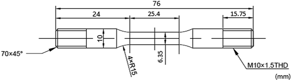 | ||
| Fig. 2 Schematic of the specimen for SSRT tests. | ||
The results of SSRT corrosion tests, including the time to failure, maximum stress, and strain, were compared with the parameters obtained in the inert environment. The comparison indicates SCC susceptibility under different conditions. SCC susceptibility can be expressed using break elongation, the reduction of area, tensile strength, energy absorption, and fracture time.39 SCC susceptibility at three temperatures was compared. To evaluate the degree of stress corrosion, the variations in strength, breaking elongation, and area reduction as well as the fracture time before and after stress corrosion were observed.40
 | (2) |
 | (3) |
 | (4) |
where Iδ, Iφ, and ITFR are SCC susceptibility parameters corresponding to specimen elongation, area reduction, and fracture time, respectively. δine and δcor represent specimen elongation after fracture in inert and corrosive environments, respectively. Similarly, φine and φcor denote specimen area reduction in inert and corrosive environments, respectively. tine represents specimen fracture time in an inert medium, whereas tcor represents specimen fracture time in corrosive environments, respectively. An increase in the values of the SCC susceptibility parameter indicates an increased susceptibility to SCC.
2.3 Four-point bending corrosion tests
Four-point bending tests were performed on specimens to determine the composition of corrosion products of super 13Cr steel under stress. The tests were conducted in alignment with the ISO 7439-2 standard, and 30 day immersion tests were performed at 120 °C and 150 °C with 1 MPa CO2. For each test, three specimens were placed in the autoclave. Beams were subjected to static loading 90% of actual yield strength (AYS) at 120 °C and 150 °C. At the end of each experiment, the specimens were ultrasonically cleaned, rinsed with deionized water, and dried with ambient temperature air. The specimens were then stored in a desiccator until required, and the morphology and elemental composition of the corrosion products were analyzed using a combination of SEM/EDS (JEOL, JSM-6510A) and XPS (ULVAC-PHI, PHI Quantro SXM, Al mono).2.4 Electrochemical experiments
Electrochemical experiments (Gamry, reference 600+) were performed at temperatures ranging from 120 °C to 150 °C under 1 MPa CO2 or 1 MPa N2 in the autoclave. A standard three-electrode system was used with 13Cr steel as a working electrode, an Ag/AgCl reference electrode (UltraDeg®, Multi Local Corr Probe 1000), and a platinum counter electrode (Fig. 3). Specimens of 13Cr steel with dimensions of 10 × 10 × 3 mm3 were mounted on plastic tubes and sealed with epoxy resin. The entire surface was wet polished up to 1000 grit; mirror finished using 2000-SiC paper; rinsed with distilled water, acetone, and alcohol; and dried under ambient temperature air. Potentiodynamic curves were obtained by polarizing the working electrode at potentials ranging from −100 mV below the OCP to convenient potential values at a scan rate of 0.5 mV s−1. Furthermore, electrochemical impedance spectroscopy (EIS) was performed at an OCP of 10 mV AC and a frequency range of 10![[thin space (1/6-em)]](https://www.rsc.org/images/entities/char_2009.gif) 000–0.01 Hz. The OCP was kept constant for at least 1 h prior to the start of each experiment.
000–0.01 Hz. The OCP was kept constant for at least 1 h prior to the start of each experiment.
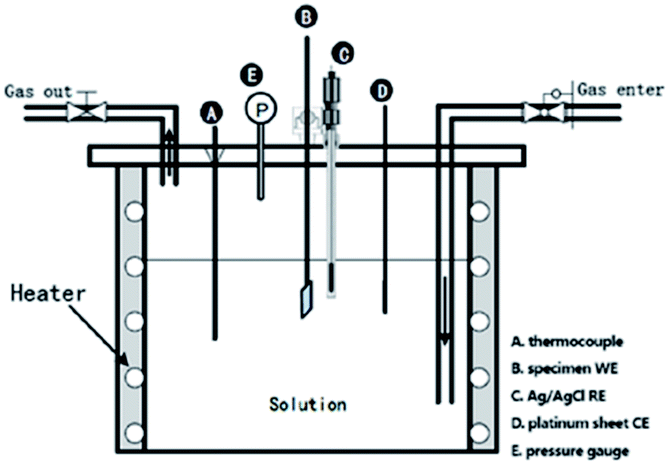 | ||
| Fig. 3 Schematic diagram of the electrochemical autoclave showing the electrode locations. | ||
3. Results and discussion
3.1 SCC susceptibility
Fig. 4 shows the stress–strain curves of super 13Cr steel at 120 °C, 140 °C, and 150 °C, which were obtained through the SSRT test. The results indicate a considerable decrease in fracture strain in a 16 wt% NaCl solution under 1 MPa CO2 atmosphere at all three tested temperatures. The SCC susceptibility could be determined with reference to eqn (2)–(4) as shown in Fig. 5. The results showed that all three parameters of the specimens exposed to the 16 wt% NaCl solution under a 1 MPa CO2 atmosphere increased significantly when the temperature was increased, especially up to 150 °C.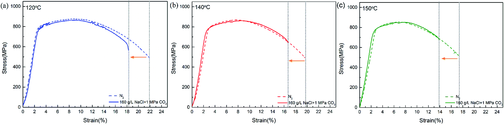 | ||
| Fig. 4 Stress–strain curves of super 13Cr steel at (a) 120 °C, (b) 140 °C, and (c) 150 °C. | ||
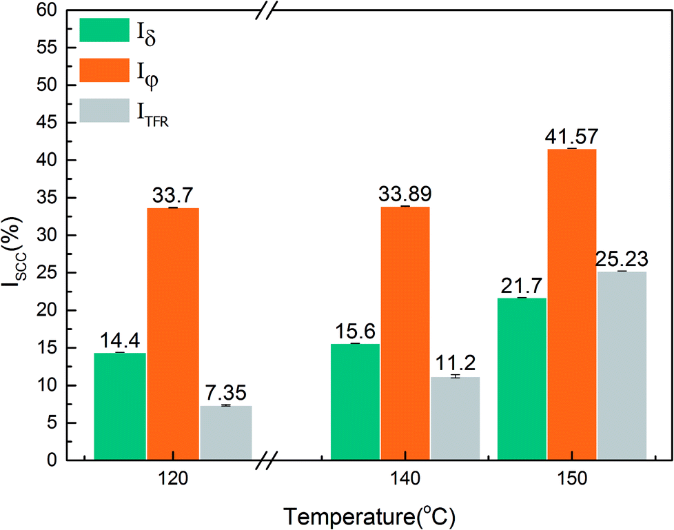 | ||
| Fig. 5 SCC susceptibility parameters of super 13Cr steel at 120 °C, 140 °C, and 150 °C. | ||
To clarify the primary factors responsible for the increase in the values of SCC susceptibility parameters, the macromorphology of the fracture surface was assessed.2,25,38,39,41–43 Fig. 6 shows the macromorphology of fracture surface after SSRT corrosion tests. The images indicated that there was no difference in inert environment at three temperatures (Fig. 6(a)–(c)). For the specimens exposed to the 16 wt% NaCl solution with 1 MPa CO2 atmosphere, as shown in Fig. 6 (d)–(f), a noticeable amount of corrosion occurred on the surface and SSRT fracture initiation sites that were identified through fractography.44,45 Under the same loading rates, as the temperature increased, the fracture initiation site moved toward the edge.
 | ||
| Fig. 6 Macroscopic morphologies of super 13Cr steel after stress corrosion in inert environment at (a) 120 °C, (b) 140 °C, and (c) 150 °C and in 16 wt% NaCl solution under a 1 MPa CO2 atmosphere at (d) 120 °C, (e) 140 °C, and (f) 150 °C. | ||
Fig. 7 displays the micromorphologies of crack origins for super 13Cr steel exposed to inert environments and the 16 wt% NaCl solution under a 1 MPa CO2 atmosphere at three temperatures. The large dimples produced by second-phase particles were selected as a reference for analysis because several of these dimples were present on the super 13Cr steel surface in the inert medium, and the increase in temperature did not cause any evident change in the morphology. However, in a corrosive environment, the number of the dimples considerably decreased at 120 °C, 140 °C, and 150 °C. The changes in the dimples were primarily caused by increased plastic damage during dynamic tearing. According to Stroh's theory, the stress concentration of any fracture in the specimen can result in only two possible behaviors: the activation of Frank–Read sources causing ductile fracture and the production of microcracks promoting brittle fracture. Numerous experiments have proven that anodic dissolution type SCC at high temperature does not feature continuous initiation and propagation.46–49 Microcracks were initiated in different spaces and then connected with each other through the plastic tearing,49 forming a quasi-cleavage fracture surface. A quasi-cleavage crack generally occurs because of holes, impurities, and hard points in the grain, which are also a source of large dimples in an inert environment. Therefore, SCC susceptibility can be determined through the observation of characteristics of the large dimples in the fracture. Furthermore, because the crack propagation of both ductile fracture and quasi-cleavage fracture was observed along the tear ridges, the ratio of cleavage microcracks in the expansion process could be used to assess SCC susceptibility. At 120 °C, the tear ridges appears on the edge of the dimples, whereas at 140 °C, some areas without dimples were surrounded by tear ridges which may due to the propagation of cleavage microcracks. When the temperature was increased up to 150 °C, the number of dimples substantially decreased and several short, curved tear ridges emerged, exhibiting typical quasi-cleavage embrittlement cracking.
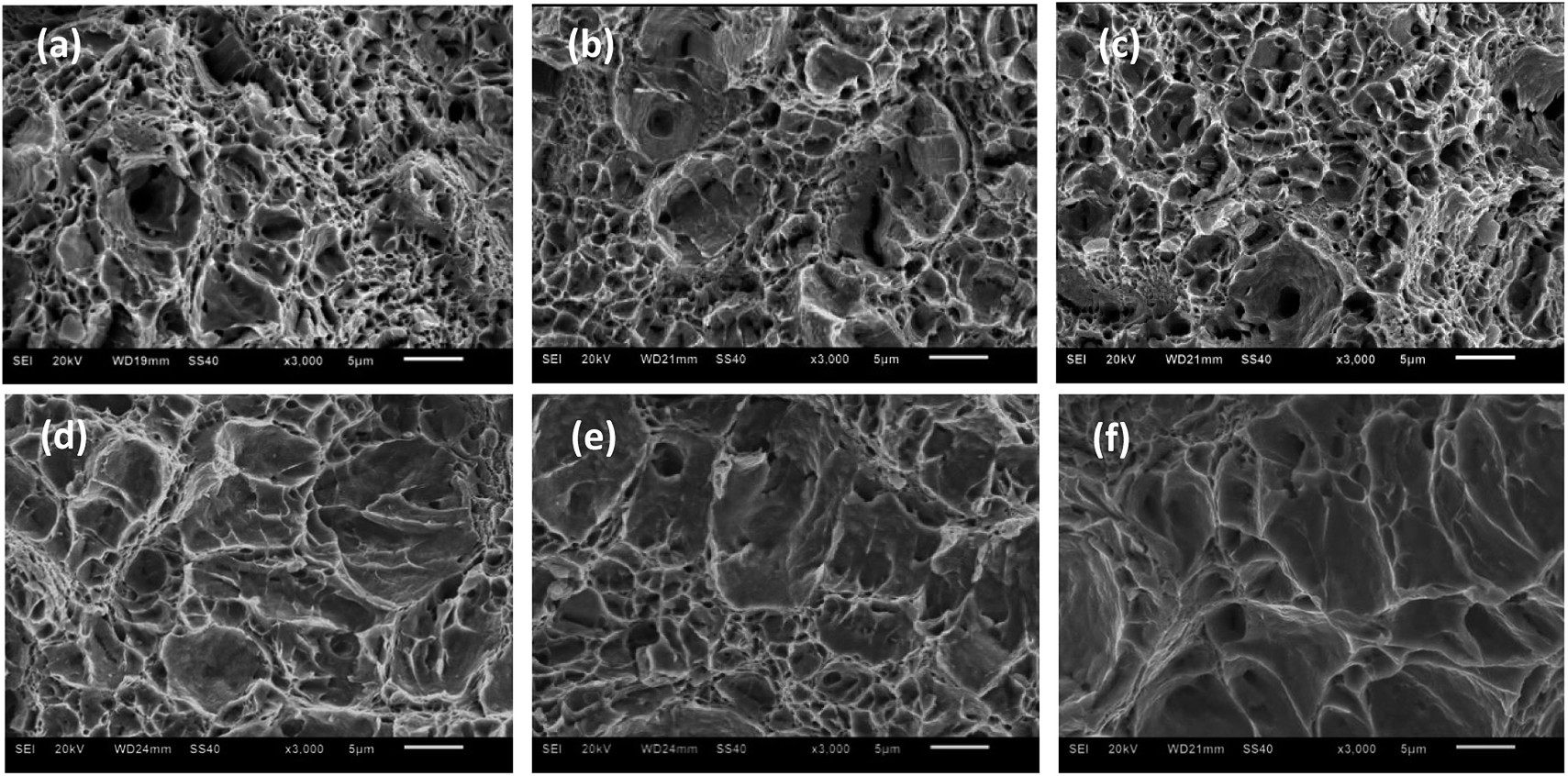 | ||
| Fig. 7 Microscopic morphologies of SSRT fracture of super 13Cr steel in inert environment at (a) 120 °C, (b) 140 °C, and (c) 150 °C and in 16 wt% NaCl solution under a 1 MPa CO2 atmosphere at (d) 120 °C, (e) 140 °C, and (f) 150 °C. | ||
Fig. 8 presents the SEM images of cross-sections of super 13Cr steel exposed to the 16 wt% NaCl solution under a 1 MPa CO2 atmosphere at 120 °C, 140 °C, and 150 °C, among which Fig. 8(d)–(f) are high-magnification images obtained after rotating Fig. 8(a)–(c) by 90°. The images indicated that all steel specimens exhibited significant necking, and typical cup-and-cone fracture surfaces was observed at temperatures of 120 °C and 140 °C, as shown in Fig. 8(a) and (b), respectively. However, the typical image of a shear-type fracture was observed at 150 °C. The fracture angle was approximately 45° in the direction of the applied tensile stress, as shown in Fig. 8(c). The specimen exhibited a low value of φcor despite necking.44
 | ||
| Fig. 8 SEM transverse side image of the fractures in 16 wt% NaCl solution under a 1 MPa CO2 atmosphere at (a) 120 °C, (b) 140 °C, and (c) 150 °C. SEM transverse side image of (d) pitting corrosion on the side surface of (a) and (e) pitting corrosion on the side surface of (b), and (f) pitting corrosion on the side surface of (c). | ||
The high-magnification images of the steel cross-section in Fig. 8(d) and (e) show pits observed on the surface at 120 °C and 140 °C. Observation of the entire section indicated that no obvious cracks originating from pits. However, the pits did not exhibit lateral growth and caused crack propagation at 150 °C. Therefore, the fracture initiation sites were observed at the edges of specimens, and corrosion was crucial in causing fractures.
3.2 Relation between SCC susceptibility and passivation properties
As the temperature increased, material cracking was not a mechanical process but a corrosion-dominated process.43 According to the results of SSRT tests, the SCC susceptibility was associated with pitting corrosion resistance, which depends on the stability of the passivation film for stainless steel.12,50Fig. 9 presents the SEM image of the cross-section of four-point bending specimens subjected to an AYS of 90% exposed to the 16 wt% NaCl solution at 120 °C and 150 °C with 1 MPa CO2 for 30 days. The images showed that the thicknesses of the corrosion scales were approximately 2 and 5 μm, respectively, and this corrosion scale layer was not a nanoscale thickness passivation film with good pitting corrosion resistance. Abnormal thickening indicated that an extremely porous and relatively noncompact layer covered the entire super 13Cr steel surface. This corrosion product layer could be easily crushed after unloading the stress (Fig. 9(b)) as the temperature increased from 120 °C to 150 °C.
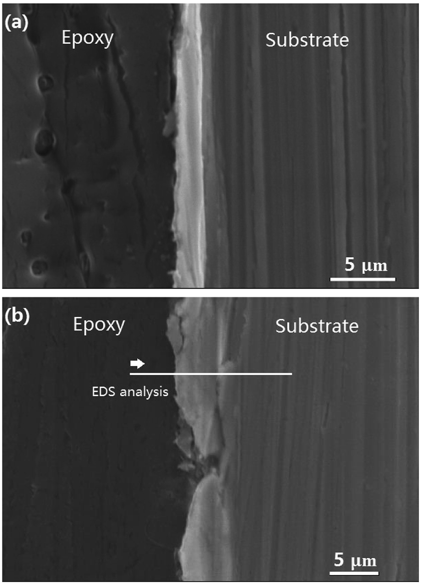 | ||
| Fig. 9 Cross sectional morphology of four-point bending specimens subjected to an AYS of 90% after 30 days immersion in 16 wt% NaCl solution at (a) 120 °C; (b) 150 °C; and 1 MPa CO2 partial pressure. | ||
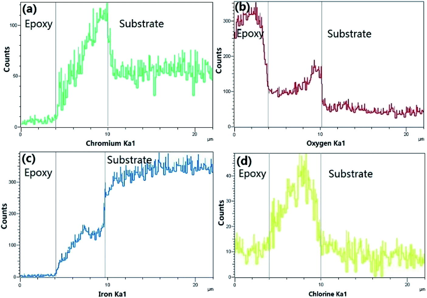
Fig. 10 provides the EDS analysis of super 13Cr steel cross-section and the elemental compositions of corrosion products at 150 °C. The potential elements of corrosion products include Fe, Cr, O, and Cl. The results indicated the corrosion product layer contained a considerable amount of Cr. However, Cl− was present in the corrosion product layer, which indicated the porosity of the film.
 | ||
| Fig. 10 Cross sectional EDS of Fig. 9(b). | ||
XPS spectra were used to determine the corrosion products formed on the steel surface (Fig. 11). XPS analysis was used to detect the presence of any potential amorphous and crystalline products. The elements of interest on the steel surface were Fe, Cr, and O.
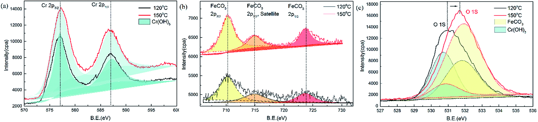 | ||
| Fig. 11 XPS spectra for (a) Cr2p, (b) Fe2p, (c) O1s detected for corrosion scales formed on super 13Cr stainless steel after 30 days of exposure in 16 wt% NaCl solution at 120 °C and 150 °C and 1 MPa CO2 partial pressure. | ||
The results of Cr2p1/2 and Cr2p3/2 binding energies for super 13Cr steel validated the presence of Cr(OH)3 on the surface. The binding energy peaks at 586.8 eV and 577.0 eV indicated that Cr was bound to oxygen in the 3+ oxidation state. The potential compound corresponding to these binding energies was Cr(OH)3, as shown in Fig. 11(a).51
In the Fe2p region, as shown in Fig. 11(b), the binding energy peaks at 723.7 eV (Fe2p1/2), 714.9 eV (Fe2p3/2, satellite), and 710.2 eV (Fe2p3/2) for FeCO3 (ref. 52) were detected on the specimen surfaces at 120 °C and 150 °C.
O1s analysis indicated that FeCO3 and Cr(OH)3 formed on the specimen sample surfaces after being exposure to the 16 wt% NaCl solution at 120 °C and 150 °C. The binding energy peaks for Cr(OH)3 (ref. 51) and FeCO3 (ref. 52) were observed at 530.8 and 531.9 eV, respectively. The peak position shifted because of the change in the proportion of composition, with a decrease in the Cr(OH)3 proportion and an increase in the FeCO3 proportion. Considering that FeCO3 is less dense and protective than Cr(OH)3,24 the changes in the film composition on super 13Cr stainless steel can be concluded as the primary factor causing porosity, which correlates to increased SCC susceptibility.
3.3 The degradation of the passivation characteristics
Fig. 12(a) and (b) show the potentiodynamic curves of super 13Cr steel for the test solution with 1 MPa CO2/N2 at three temperatures. The exposure time of the whole tests was within 3 hours to avoid the inhomogeneity of the sample surface. Super 13Cr steel was in a passive state at 120 °C and 140 °C. At 150 °C, the anodic curve exhibited an evident current density peak especially in the CO2 atmosphere and indicated the active–passive behavior of super 13Cr steel. The corrosion potential (Ecorr vs. Ag/AgCl electrode) shifted in the negative direction as the temperature increased, which implies the less stable characteristic of super 13Cr steel.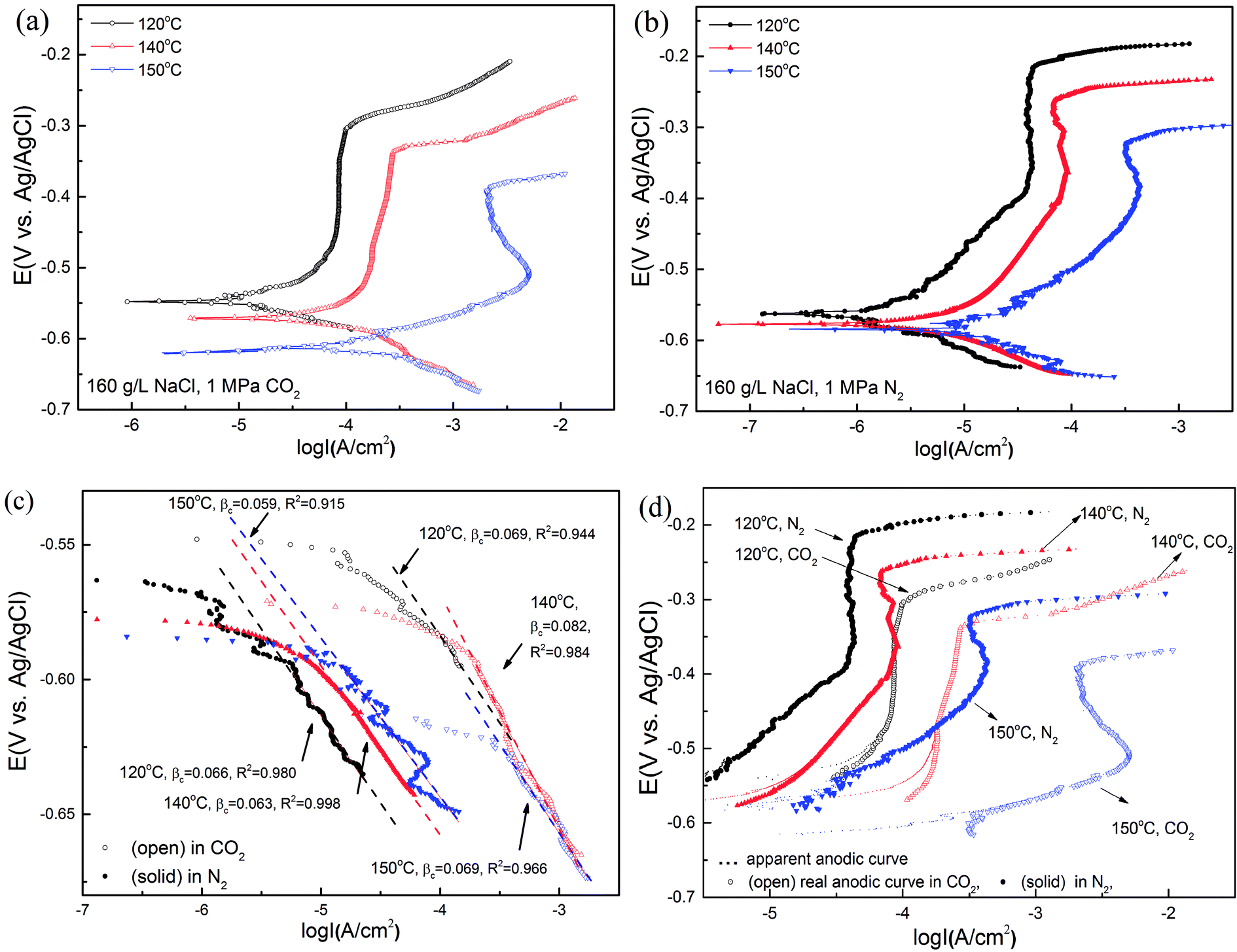 | ||
| Fig. 12 Potentiodynamic curves of super 13Cr steel in 16 wt% NaCl solution in a (a) 1 MPa CO2; (b) 1 MPa N2 atmosphere at 120 °C, 140 °C, and 150 °C; (c) cathodic fitting curves; (d) correction of the apparent anodic curves. | ||
In this study, cathodic sweeps for three temperatures were similar (Fig. 12(c)). In a N2 atmosphere, the cathodic reactions is direct H2O reduction, which is under charge transfer control.53 The values of βc in a CO2 atmosphere were bigger than those in a N2 atmosphere at the same temperature, which indicated the participation of H+ and H2CO3 reduction.12 Increasing temperature has a small influence on the cathodic reaction, but accelerates the anodic reaction greatly. The actual anodic current density could be observed after the correction of the hydrogen evolution reaction (HER)54 (Fig. 12(d)), indicating an increment in corrosion current density and a decrement in the area of the passive potential region with increasing temperature. Furthermore, compared with chloride-only solutions, the pitting potential (Ep vs. Ag/AgCl electrode) in chloride solutions with CO2 at the same temperature considerably decreased and exhibited high corrosion current density. The results suggested that the transpassivation of super 13Cr can easily occur at high temperatures because of the reduction in the area of the passive potential region, which may increase SCC susceptibility.
To determine reasons for the degradation of the passivation film and the initial corrosion process occurring at the interface, EIS measurements were recorded for each specimen at the end of OCP measurements.
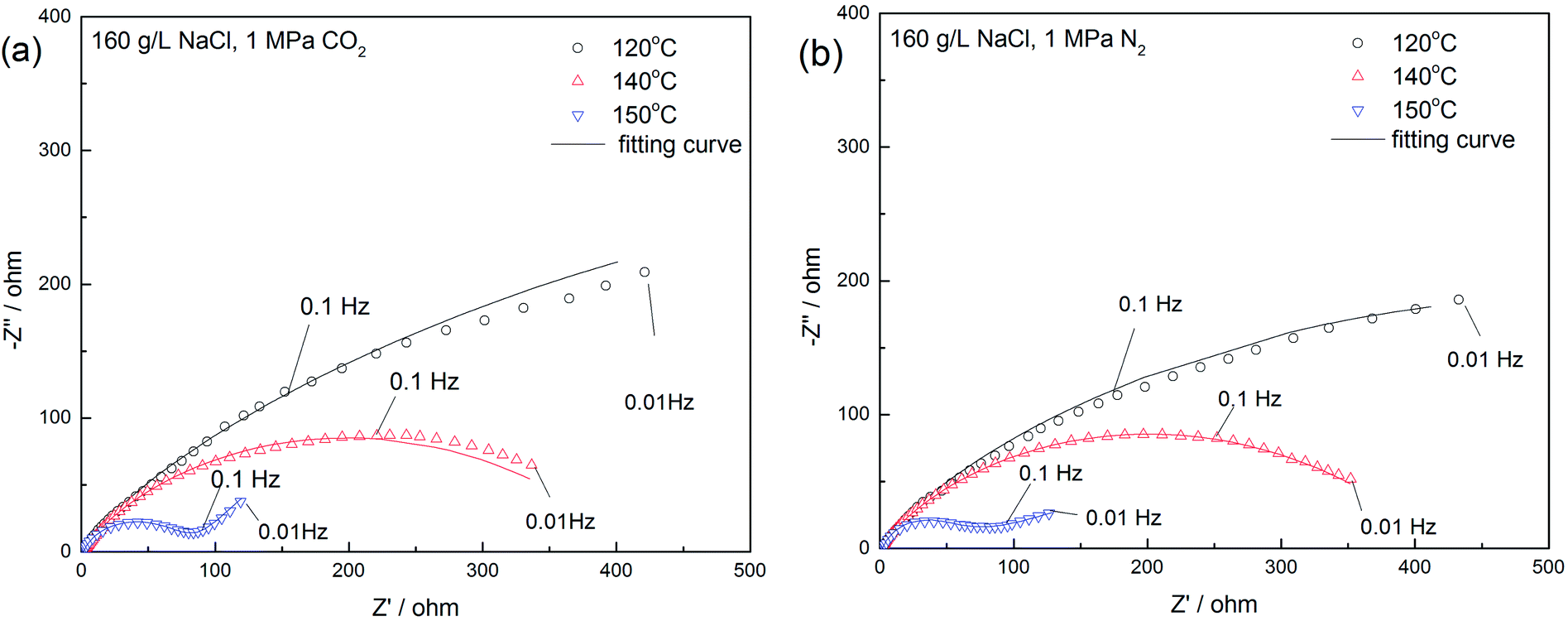
Fig. 13 presents the Nyquist plots of the specimens exposed to the 16 wt% NaCl solution under a 1 MPa CO2 at three temperatures. The exposure time of the whole tests was within 3 hours to avoid the inhomogeneity of the sample surface. The diameter of the depressed semicircle substantially reduced as the temperature increased, indicating the frailty of the passivation film at high temperatures.50 Moreover, the diffusion process occurred at a low frequency and the temperature of 150 °C, corresponding to the weakening of the film caused by porosity.
 | ||
| Fig. 13 Nyquist plots for 16 wt% NaCl solution in a (a) 1 MPa CO2; (b) 1 MPa N2 atmosphere at 120 °C, 140 °C, and 150 °C. | ||
The obtained results were modeled using an equivalent circuit, as shown in Fig. 14. Here, Rs, Rct, and Rfilm are the electrolyte, charge transfer, and film resistances, respectively. CPEdl and CPEfilm are constant phase elements (CPE) representing the electric double layer capacitance and the film capacitance, respectively. To conform to the squashed capacitive loop formed at high temperatures, using a CPE is more efficient than using a pure capacitance element Cdl. The impedance of CPE is expressed as55,56
| ZCPE = P−1(iω)−n | (5) |
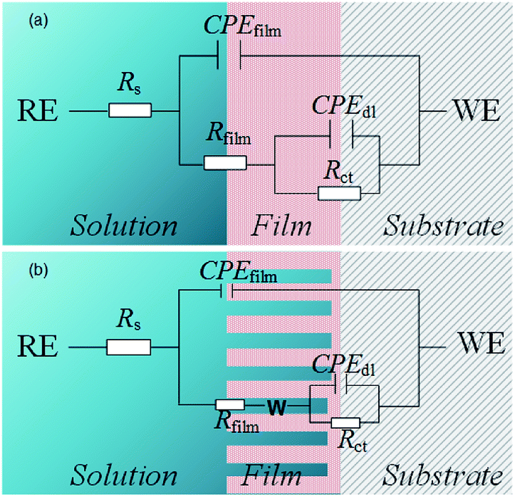 | ||
| Fig. 14 Equivalent circuit used in the modeling of the EIS results. (a) 120–140 °C; (b) 150 °C. | ||
Furthermore, the internal solution fills the holes, indicating that the holes are also a resistance component. When the inhomogeneity of the film is not evident, the equivalent circuit is simplified by including the resistance of the hole in Rfilm (Fig. 14(a)). However, as the depth of the holes gradually increases at high temperatures, the film becomes porous and loose. Therefore, introducing the Warburg impedance (Warg) to simulate the diffusion process in porous structures is necessary (Fig. 14(b)). Warg is the argument of diffusion impedance, which represents diffusion distribution. When Warg is slightly less than π/4, the film approximates to planar semi-infinite diffusion. As Warg decreases, the film exhibits spherical semi-infinite diffusion characteristics,57 indicating a reduction in the diffusion space in the inner film.
Table 2 illustrates the EIS test results. For all temperatures, the values of Rs remained nearly constant, but the parameters of outer and inner films were evidently correlated to the temperature. A comparison between the values of Rfilm and Rct indicates that the inner film is crucial for corrosion resistance. Rct decreased with an increase in temperature, indicating increased corrosion at high temperatures.58 This reduction could be attributed to two factors: an increment in the porosity of the inner film and changes in the composition of the film.59 In a relatively porous film an increment of P of CPE should be observed because of water filling in the pores,60–62 and the result was in agreement with test results for chloride-only solutions. However, this behavior was not observed when CO2 was in the atmosphere. Therefore a decrease in Rct was probably also related to changes in the composition that impact electronic properties.63 A previous composition analysis indicated that the Cr(OH)3/FeCO3 ratio decreased at high temperatures, which validated the hypothesis of the EIS test.
| T/°C | Atmosphere | Rs/Ω cm2 | CPEfilm | Rfilm/Ω cm2 | CPEdl | Rct/kΩ cm2 | Warg/rad | ||
|---|---|---|---|---|---|---|---|---|---|
| P/×10−4 Ω−1 cm−2 Sn | n | P/×10−4 Ω−1 cm−2 Sn | n | ||||||
| 120 | CO2 | 0.30 | 45 | 0.38 | 3.1 | 15 | 0.78 | 1.4 | — |
| 140 | 0.36 | 24 | 0.46 | 2.8 | 2.7 | 0.82 | 0.39 | ||
| 150 | 1.03 | 9.6 | 0.61 | 2.8 | 0.2 | 1 | 0.077 | 0.70 | |
| 120 | N2 | 0.36 | 38 | 0.38 | 3.1 | 12 | 0.76 | 1.5 | — |
| 140 | 0.36 | 20 | 0.46 | 2.8 | 19 | 0.82 | 0.42 | ||
| 150 | 1.75 | 1.3 | 0.87 | 0.5 | 94 | 0.84 | 0.18 | 0.31 | |
When the temperature reached 150 °C, the corrosion resistance of the film was reduced because of severe porosity caused by the diffusion process. The argument of diffusion impedance in a CO2 atmosphere was evidently larger than that in a N2 atmosphere, generating more porous structures in the inner film.
Regardless of whether the specimens were in a CO2 atmosphere, Rct evidently decreased as the increase in temperature, indicating that the high concentration of Cl− is crucial for porosity. A combination of the variation in the argument of diffusion impedance and Rct at 150 °C indicates that under CO2 conditions, changes in the composition are responsible for the degradation of the porous film. On the basis of this conclusion, it can be deduced that the dissolved CO2 further damages the film by dehydroxylating carbonic acid and increasing the ionic conductivity of the film64 and finally degrading corrosion resistance inside and outside the film.
Fig. 15 illustrates the system under conditions that induce pitting corrosion in the presence of a high concentration of Cl− at high temperatures and high CO2 partial pressure. Fig. 15(a) presents the adsorption of active Cl− at the initial stage followed by Cl− deposition on the film surface. Super 13Cr steel is then readily susceptible in the solution containing Cl−, which leads to porosity on the film.65 Moreover, the cathodic process facilitates the hydrolysis reaction of dissolved CO2, and eventually produces FeCO3 (Fig. 15(b)). The Cr(OH)3/FeCO3 ratio of corrosion product films decreased, which promotes Cl−-induced film degradation and finally causes pitting corrosion. When the pitting corrosion is developed up to a certain depth in a direction perpendicular to the applied stresses, the occurrence of crack propagation originating from the pits is observed (Fig. 15(c)).
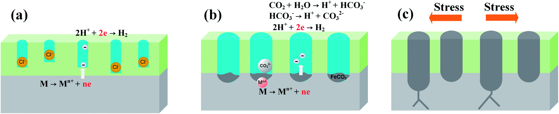 | ||
| Fig. 15 Schematic model for the formation process of SCC on the steel surface; (a) original pitting corrosion induced by adsorbed Cl−, (b) acceleration effect of CO2 on pitting corrosion development, and (c) crack originating from pitting corrosion. | ||
4. Conclusion
The primary aim of this study was to understand the critical temperature for the SCC susceptibility of super 13Cr steel in simulated formation water and determine the primary cause of SCC susceptibility. The main conclusions of this study are listed as follows:• Temperature can influence the SCC of super 13Cr steel and increase the risk of material failure. Super 13Cr steel exposed to the 16 wt% NaCl solution was highly resistant to SCC at temperatures less than 140 °C. However, material failure in terms of embrittlement cracking was observed as the temperature increased up to 150 °C.
• The results of potentiodynamic curves indicate that a change in anodic processes caused the degradation of the protective film on super 13Cr stainless steel. The cathodic process was similar at three temperatures in a CO2 environment. In the 16 wt% NaCl solution under 1 MPa CO2 atmosphere at 150 °C, the anodic and cathodic curves intersected the active–passive zone and therefore showed the risk of SCC susceptibility caused by corrosive pitting.
• Evident cracks were observed on super 13Cr steel exposed to the 16 wt% NaCl solution in a CO2 environment. The instability of corrosion product films is the primary factor resulting in stress corrosion. At 150 °C, high concentration of Cl− is crucial for porosity, whereas CO2 reduces the Cr(OH)3/FeCO3 ratio in the inner film, which further promotes Cl−-induced porosity and finally reduces film corrosion resistance.
Conflicts of interest
There are no conflicts to declare.Acknowledgements
This work was supported by the National Science and Technology Major Project (No. 2016ZX05028-004) and the National Natural Science Foundation of China (Grant No. 51371034).References
- P. Felton and M. J. Schofield, Anal. Chim. Acta, 1998, 58, 470–472 Search PubMed.
- H. Marchebois, J. Leyer and B. Orlans-Joliet, in CORROSION 2007, NACE International, 2007 Search PubMed.
- H. Marchebois, H. E. Alami, J. Leyer and A. Gateaud, in CORROSION 2009, NACE International, 2009 Search PubMed.
- R. B. Rebak and T. E. Perez, in CORROSION 2017, NACE International, 2017 Search PubMed.
- A. Ikeda, M. Ueda and S. Mukai, in CORROSION 83, NACE International, 1983 Search PubMed.
- L. Smith, Br. Corros. J., 2013, 34, 247–253 CrossRef.
- J. Meng, J. Skogsberg, B. Chambers, M. Kimura, R. Kane, and K. Shimamoto, in CORROSION 2011, Paper: 11100., NACE International, 2011 Search PubMed.
- T. G. Gooch and R. N. Gunn, Mater. Perform., 1995, 34, 58–61 Search PubMed.
- D. Fischer, C. Li, W. Huang and W. Sun, in CORROSION 2016, NACE International, 2016 Search PubMed.
- J. Enerhaug, P. E. Kvaale, M. Bjordal, J. M. Drugli and T. Rogne, in CORROSION 99, NACE International, 1999 Search PubMed.
- J. Enerhaug, S. L. Eliassen and P. E. Kvaale, in CORROSION 97, NACE International, 1997 Search PubMed.
- L. Mu and W. Zhao, Corros. Sci., 2010, 52, 82–89 CrossRef.
- M. Kimura, Y. Miyata, K. Sakata and R. Mochizuki, in CORROSION 2004, NACE International, 2004 Search PubMed.
- T. J. Mesquita, E. Chauveau, M. Mantel, N. Bouvier and D. Koschel, Corros. Sci., 2014, 81, 152–161 CrossRef.
- S. Tavares, F. da Silva, C. Scandian, G. da Silva and H. de Abreu, Corros. Sci., 2010, 52, 3835–3839 CrossRef.
- T. Cassagne, M. Bonis, C. Duret and J. L. Crolet, in CORROSION 2003, NACE International, 2003 Search PubMed.
- M. Kimura, Y. Miyata, T. Toyooka and Y. Kitahaba, Corrosion, 2001, 57, 433–439 CrossRef.
- X. Lei, Y. Feng, J. Zhang, A. Fu, C. Yin and D. Mac, Electrochim. Acta, 2016, 191, 640–650 CrossRef.
- D. Du, K. Chen, H. Lu, L. Zhang, X. Shi, X. Xu and P. Andresen, Corros. Sci., 2016, 110, 134–142 CrossRef.
- C. P. Sturrock and W. F. Bogaerts, Corrosion, 2012, 53, 333–343 CrossRef.
- S. Asamoto, Y. L. Guen, O. Poupard and B. Capra, Engineering Computations, 2013, 30, 842–853 CrossRef.
- S. D. Zhu, J. F. Wei, R. Cai, Z. Q. Bai and G. S. Zhou, Eng. Failure Anal., 2011, 18, 2222–2231 CrossRef.
- R. D. Kane and J. Burman, in CORROSION 2012, NACE International, 2012 Search PubMed.
- Y. Liu, L. Xu, M. Lu, M. Yao, J. Zhu and L. Zhang, Appl. Surf. Sci., 2014, 314, 768–776 CrossRef.
- L. Calabrese, L. Bonaccorsi, M. Galeano, E. Proverbio, D. Pietro and F. Cappuccini, Corros. Sci., 2015, 98, 573–584 CrossRef.
- L. Wei, X. Pang and K. Gao, Corros. Sci., 2016, 111, 637–648 CrossRef.
- M. Iannuzzi, C. Mendez, L. Avila-Gray, G. Maio and H. Rincón, in CORROSION 2010, NACE International, 2010 Search PubMed.
- A. Ikeda, S. Mukai and M. Ueda, Corrosion, 1985, 41, 185–192 CrossRef.
- S. Marcelin, N. Pébère and S. Régnier, Electrochim. Acta, 2013, 87, 32–40 CrossRef.
- X. Yue, Int. J. Electrochem. Sci., 2017, 12, 7853–7868 CrossRef.
- D. T. Hoelzer, B. A. Pint and I. G. Wright, J. Nucl. Mater., 2000, 283, 1306–1310 CrossRef.
- R. K. S. Raman, R. Rihan and R. N. Ibrahim, J. Electrochem. Soc., 2007, 154, C658–C662 CrossRef.
- E. Jafari, J. Mater. Sci. Technol., 2010, 26, 833–838 CrossRef.
- K. M. Kim, H. P. Jin, H. S. Kim, J. H. Kim, Y. L. Yun and K. Y. Kim, Int. J. Hydrogen Energy, 2012, 37, 8459–8464 CrossRef.
- A. R. Despic, R. G. Raicheff and J. O. Bockris, J. Chem. Phys., 1968, 49, 926–938 CrossRef.
- X. Zhong, S. C. Bali and T. Shoji, Corros. Sci., 2017, 118, 143–157 CrossRef.
- L. F. Garfias-Mesias, J. M. Sykes and C. D. S. Tuck, Corros. Sci., 1996, 38, 1319–1330 CrossRef.
- R. Nishimura and Y. Maeda, Corros. Sci., 2004, 46, 769–785 CrossRef.
- M. Nakahara and T. Shoji, Corrosion, 1996, 52, 634–642 CrossRef.
- NACE International, in Standard, NACE International, 2016.
- A. Contreras, M. A. Espinosa-Medina and M. Salazar, in International Pipeline Conference, 2008, pp. 547–555 Search PubMed.
- S. Mahajanam, R. Case, K. Cloke, J. Daniels, J. Dunn, and F. Bredal, in CORROSION 2014, Paper: 2014-3983., NACE International, 2014 Search PubMed.
- X. Guo, T. Shi, Z. Zhang and B. Ma, J. Nat. Gas Sci. Eng., 2016, 29, 134–140 CrossRef.
- J. Venezuela, Q. Liu, M. Zhang, Q. Zhou and A. Atrens, Corros. Sci., 2015, 99, 98–117 CrossRef.
- M. Salazar, M. A. Espinosamedina, P. Hernández and A. Contreras, Corros. Eng., Sci. Technol., 2011, 46, 464–470 CrossRef.
- Y. H. Lu, Q. J. Peng, T. Sato and T. Shoji, J. Nucl. Mater., 2005, 347, 52–68 CrossRef.
- L. J. Qiao, K. W. Gao, A. A. Volinsky and X. Y. Li, Corros. Sci., 2011, 53, 3509–3514 CrossRef.
- J. I. Dickson, D. Groulx, S. Li and D. Tromans, Mater. Sci. Eng., 1987, 94, 155–173 CrossRef.
- T. J. Marrow, L. Babout, A. P. Jivkov, P. Wood, D. Engelberg, N. Stevens, P. J. Withers and R. C. Newman, J. Nucl. Mater., 2006, 352, 62–74 CrossRef.
- N. Ebrahimi, M. Momeni, A. Kosari, M. Zakeri and M. H. Moayed, Corros. Sci., 2012, 59, 96–102 CrossRef.
- E. Desimoni, C. Malitesta, P. G. Zambonin and J. C. Rivière, Surf. Interface Anal., 1988, 13, 173–179 CrossRef.
- J. Heuer and J. Stubbins, Corros. Sci., 1999, 41, 1231–1243 CrossRef.
- Y. Zheng, B. Brown and S. Nesic, Corrosion, 2014, 71, 316–325 CrossRef.
- Z. B. Wang, H. X. Hu and Y. G. Zheng, Electrochim. Acta, 2015, 170, 300–310 CrossRef.
- C. Cao and J. Zhang, Electrochemical impedance spectroscopy introduction, Science Press, Beijing, 2002 Search PubMed.
- N. Ayati, M. Momeni, M. H. Moayed, A. Davoodi and M. Rahimizadeh, Mater. Chem. Phys., 2011, 126, 873–879 CrossRef.
- C. N. Cao and J. Q. Zhang, 2002, 86–106.
- M. Hoseinpoor, M. Momeni, M. H. Moayed and A. Davoodi, Corros. Sci., 2014, 80, 197–204 CrossRef.
- C. Liu, Q. Bi, A. Leyland and A. Matthews, Corros. Sci., 2003, 45, 1257–1273 CrossRef.
- M. J. Esplandiu, E. M. Patrito and V. A. Macagno, Electrochim. Acta, 1995, 40, 809–815 CrossRef.
- M. E. Folquer, L. M. Gassa, S. G. Real and S. B. Ribotta, Corros. -Houst. Tx-, 2002, 58, 240–247 CrossRef.
- N. Ebrahimi, M. Momeni, A. Kosari, M. Zakeri and M. H. Moayed, Corros. Sci., 2012, 59, 96–102 CrossRef.
- W. Xu, K. Daub, X. Zhang, J. J. Noel, D. W. Shoesmith and J. C. Wren, Electrochim. Acta, 2009, 54, 5727–5738 CrossRef.
- J. Banaś, U. Lelek-Borkowska, B. Mazurkiewicz and W. Solarski, Electrochim. Acta, 2007, 52, 5704–5714 CrossRef.
- L. B. Niu and K. Nakada, Corros. Sci., 2015, 96, 171–177 CrossRef.
| This journal is © The Royal Society of Chemistry 2018 |