
 Open Access Article
 This Open Access Article is licensed under a Creative Commons Attribution-Non Commercial 3.0 Unported Licence
Synthesis of dimethyl carbonate from CO2 and methanol over a hydrophobic Ce/SBA-15 catalyst†
Yanfeng Pu a,
Keng Xuanab,
Feng Wanga,
Aixue Liab,
Ning Zhao*a and
Fukui Xiao*a
a,
Keng Xuanab,
Feng Wanga,
Aixue Liab,
Ning Zhao*a and
Fukui Xiao*a
aState Key Laboratory of Coal Conversion, Institute of Coal Chemistry, Chinese Academy of Sciences, Taiyuan 030001, PR China. E-mail: zhaoning@sxicc.ac.cn; xiaofk@sxicc.ac.cn
bUniversity of Chinese Academy of Sciences, Beijing 100049, PR China
First published on 31st July 2018
Abstract
A series of Ce/SBA-15 catalysts with different degrees of hydrophobicities were prepared via a post-grafting method and used for the direct synthesis of dimethyl carbonate (DMC) from CO2 and methanol. The Ce/SBA-15-6 catalyst exhibited the highest DMC yield of 0.2%, which was close to the equilibrium value under the reaction conditions of 130 °C, 12 h and 12 MPa. The catalysts were characterized via XRD, BET, FT-IR, solid-state 29Si MAS NMR, CA, TEM, XPS and NH3/CO2-TPD; the results indicated that the hydrophobicity of the catalysts facilitated the creation of oxygen vacancies, which could act as Lewis acids to activate methanol. Higher amounts of moderate acid sites led to higher yields of DMC. In addition, the hydrophobicity of the catalysts could also reduce the adsorbed water on their surface and increase the DMC yield while shortening the reaction time.
1 Introduction
As an environmentally friendly and biodegradable chemical feedstock,1,2 dimethyl carbonate (DMC) has been widely used as a safer alternative to poisonous dimethyl sulphate and phosgene and as a precursor for the production of polycarbonates.3,4 It can also be used as an oxygenate additive to gasoline for reducing exhaust emission due to its high oxygen content (53%).5 Compared with other synthetic routes,6 the direct synthesis of DMC from carbon dioxide and methanol is an economical and environmentally friendly route, which not only avoids the use of poisonous reagents such as phosgene and carbon monoxide,6,7 but also solves the problem of CO2 mitigation and excess methanol capacity. However, due to the thermodynamic limitations of this process,8–10 methanol conversion is very low (around 1%), and the DMC yield is far from satisfactory. Therefore, the development of high-activity and high-selectivity catalysts for the direct synthesis of DMC from methanol and carbon dioxide is necessary.It has been reported that metal tetra-alkoxides,11 metal oxides, metal acetates,12 alkali compounds,13,14 etc. show considerable catalytic performances for the direct synthesis of DMC from methanol and carbon dioxide. However, these homogeneous catalysts are difficult to separate from the products, and they are easily deactivated due to their decomposition in the presence of H2O. To overcome the above-mentioned problems, supported metal catalysts such as Cu–Ni3,15–19 and Cu–Fe20,21 have been prepared, and they show better catalytic performances in a fixed bed reactor. In addition, metal oxides, especially zirconia-based,22,23 cerium-based,24–27 and vanadium-based catalysts,28 also show good catalytic activities due to both acidic and basic sites on the catalyst surface. Especially, CeO2 is widely used as a catalyst along with a dehydrating agent and exhibits good catalytic performances.29–33 Furthermore, CeO2 can also be considered as an excellent catalyst for the activation of CO2 in the preparation of several complexes such as the complex obtained from copolymerization of CO2 and diols,34 dialkylureas from CO2 and amines,35 cyclic carbonates from CO2 and diols,36,37 cyclic ureas from CO2 and diamines,38 cyclic carbamates from CO2 and amino alcohols,39,40 and propylene carbonate from propylene glycol and CO2.41 Although CeO2 is used in the direct synthesis of DMC from CO2 and methanol9,42,43 and in other reactions, its acidity is weak. Meanwhile, it is easily deactivated due to the occupation of its active sites by adsorbed byproducts such as water.
The hydrophobic modification of a catalyst can effectively prevent the competitive adsorption of water molecules on its surface, which is beneficial for the activity and stability of the catalyst. Recently, Zhang et al.44 prepared hydrophobic organic–inorganic hybrid materials and tested them for the synthesis of diethyl carbonate (DEC) via oxidative carbonylation of ethanol in a gas-phase reaction. The results showed that hydrophobicity favored the removal of water, which reduced the adsorbed water on the active sites and inhibited the hydrolysis of DEC, thus improving the catalytic activity and stability. Besides, the enhanced hydrophobicity of the catalyst can facilitate the formation of more oxygen vacancies on CeO2,45 which could act as Lewis acid sites to activate CH3OH and improve the catalytic activity.
Herein, to enhance the surface acidity of CeO2 and reduce the adsorbed water on the active sites, a cerium-supported SBA-15 (Ce/SBA-15) catalyst was prepared and then silylated via post-grafting using hexamethyldisilazane (HMDS) as a hydrophobic solvent. This hydrophobic catalyst was first used in the direct synthesis of dimethyl carbonate from methanol and CO2. The hydrophobic functional groups effectively prevented the adsorption of water on its surface. Moreover, the surface acidity of the catalyst could be adjusted by changing the content of oxygen vacancies on CeO2. In addition, the effects of the strength and the amount of acidic sites on the catalytic activity were explored. This study is a continuation of the research on the development of efficient catalysts to synthesize DMC without a dehydrating agent, and the results will attract the attention of researchers in the field of catalyst design for CO2 conversion.
2. Experimental section
2.1 Catalyst preparation
![[thin space (1/6-em)]](https://www.rsc.org/images/entities/char_2009.gif) :50, v:v; 100 mL), water (100 mL), ethanol (100 mL) and acetone (100 mL). The powder was then dried in an oven at 150 °C for 24 h and used as the catalyst. The obtained silane-modified Ce/SBA-15 catalysts were named according to the volume of HMDS used: Ce/SBA-15-3 indicates that 3 mL HMDS was used as the silylation reagent to modify the Ce/SBA-15 catalyst, whereas Ce/SBA-15-6 and Ce/SBA-15-9 indicate the use of 6 mL and 9 mL HMDS, respectively. For comparison, an SBA-15-6 support was prepared using 6 mL HMDS to modify the SBA-15 support under the same conditions described above. The CeO2 catalyst was prepared by calcining Ce(NO3)3·6H2O at 550 °C for 6 h directly. Finally, the Ce-SBA-15-6 catalyst was prepared by mechanically mixing pure CeO2 and SBA-15-6 (0.05 g CeO2 + 0.45 g SBA-15-6).
:50, v:v; 100 mL), water (100 mL), ethanol (100 mL) and acetone (100 mL). The powder was then dried in an oven at 150 °C for 24 h and used as the catalyst. The obtained silane-modified Ce/SBA-15 catalysts were named according to the volume of HMDS used: Ce/SBA-15-3 indicates that 3 mL HMDS was used as the silylation reagent to modify the Ce/SBA-15 catalyst, whereas Ce/SBA-15-6 and Ce/SBA-15-9 indicate the use of 6 mL and 9 mL HMDS, respectively. For comparison, an SBA-15-6 support was prepared using 6 mL HMDS to modify the SBA-15 support under the same conditions described above. The CeO2 catalyst was prepared by calcining Ce(NO3)3·6H2O at 550 °C for 6 h directly. Finally, the Ce-SBA-15-6 catalyst was prepared by mechanically mixing pure CeO2 and SBA-15-6 (0.05 g CeO2 + 0.45 g SBA-15-6).2.2 Physical characterization
Powder small-angle X-ray diffraction (XRD) patterns of all the samples were collected using a Bruker D8 Advance (Germany) diffractometer with Cu Kα radiation (λ = 1.5418 Å) in the 2θ range of 1–10° and a step size of 0.04°. The wide-angle X-ray diffraction (XRD) patterns of the catalysts were measured on a Bruker D8 Advance (Germany) diffractometer equipped with a Cu Kα radiation source. The scattering intensities were measured over an angular range of 10–80° at a scanning speed of 5° min−1.The specific surface areas and pore volumes of the catalysts were measured via N2 adsorption–desorption at the liquid nitrogen temperature of 77 K using a Micromeritics Tristar II (3020) apparatus. The BET surface area was calculated from the adsorption branches in the relative pressure range of 0.05–0.25, and the total pore volume was evaluated at a relative pressure of about 0.99. The pore diameter and the pore size distribution were calculated from the desorption branch of the isotherm using the Barrett, Joyner and Halenda (BJH) equation.
Fourier transform infrared spectra (FT-IR) of the catalysts were recorded on a Nicolet Nexus 470 spectrophotometer using the KBr self-supported pellet technique over the wavelength range of 4000–400 cm−1 with 64 scans and a resolution of 2 cm−1.
Solid-state 29Si MAS NMR experiments were performed on a Bruker Avance III spectrometer operating at a Larmor frequency of 119.2 MHz with a pulse duration of 2 μs corresponding to a flip angle of π/6, recycle delay of 80 s, and spinning frequency of 9 kHz.
The hydrophobic property was investigated on Krüss GmbH, DSA-25, where the error of the measured apparent CA was found to be within ± 2°.
Transmission electron microscopy (TEM) was performed on a JEOL JEM-2100F electron microscope operated at an acceleration voltage of 200 kV.
X-ray photoelectron spectroscopy (XPS) spectra were obtained using a Thermo ESCALAB 250 spectrometer equipped with an Al Kα radiation source (hν = 1486.6 eV) under ultrahigh vacuum. The samples were dried at 150 °C in air for 24 h and then ground into a powder with a size of <0.15 mm; then, they were used for the XPS test directly. All binding energies were referenced to that of the contaminant carbon (C 1s = 284.8 eV).
Temperature-programmed desorptions of NH3 (NH3-TPD) and CO2 (CO2-TPD) were carried out on a GAM 200 mass spectrometer for the measurement of the acidity and basicity of the catalysts. Each sample (50 mg) was placed in a quartz reactor and pretreated under an Ar flow (40 mL min−1) at 500 °C for 1 h. The adsorption of NH3/CO2 was performed at 50 °C with pure NH3/CO2 (40 mL min−1) for 30 min, followed by an Ar purge for 1 h to remove physisorbed NH3/CO2. The desorption process was performed at a heating rate of 10 °C min−1 from 50 °C to 500 °C; the evolved NH3/CO2 was monitored with a thermal conductivity detector (TCD) and quantitatively analyzed using the external standard method.
2.3 DMC synthesis from methanol and CO2
The direct synthesis of DMC from methanol and carbon dioxide was carried out in a 50 mL stainless-steel autoclave equipped with a magnetic stirrer. The standard procedure is as follows: 0.5 g of catalyst (particle size <0.15 mm) was put into an autoclave and then, CO2 (99.99%; 100 mmol) was introduced into the reactor with an initial pressure of 5.0 MPa at room temperature (by adding CO2 into the reactor first, the amount of CO2 can be calculated accurately according to the ideal gas equation). Subsequently, 6.4 g of anhydrous methanol (200 mmol) was charged into the autoclave using a high-pressure liquid pump. The reactor was heated to 130 °C and simultaneously, the timer was started; the reaction pressure was maintained at 10 MPa for all experiments. The mixture was stirred for a certain period of time and then, the reactor was cooled to room temperature and depressurized. The reaction products were analyzed using a gas chromatograph (FID-GC920) equipped with a capillary column (DB-210, 25 m 0.22 mm), and benzene was added as an internal standard.3. Results and discussion
3.1 Textural and structural properties
The low-angle XRD patterns of SBA-15, Ce/SBA-15 and silylated Ce/SBA-15-X (X = 3, 6, and 9) catalysts are shown in Fig. 1a. The pattern of pure SBA-15 exhibited an intense diffraction peak at 2θ of about 0.85°, which corresponded to the (1 0 0) plane reflection of the mesostructure. The two additional weak peaks observed could be indexed to the (1 1 0) and (2 0 0) plane reflections of the hexagonal P6mm symmetry.48 These results indicated the highly ordered mesoporous structure of the samples. The intensities of the three well-resolved diffraction peaks decreased after loading with Ce, which can be due to the reduction in the extent of periodicity of SBA-15. Moreover, the (1 0 0) peak shifted slightly towards a lower angle; this suggested that the cerium species had been incorporated into the mesoporous framework of SBA-15 since the Ce–O bond length was longer than the Si–O bond length (radius of Ce4+ = 1.06 Å and Si4+ = 0.39 Å).49 Furthermore, the appearance of the same peaks for the Ce/SBA-15-X (X = 3, 6, and 9) samples revealed that the periodic ordered structure of SBA-15 was maintained after modification. The (1 0 0) peak of the silylated Ce/SBA-15-X (X = 3, 6, and 9) samples shifted slightly towards a higher angle compared to that for SBA-15, indicating reduction in pore size due to the deposition of organosilane50 (Table 1).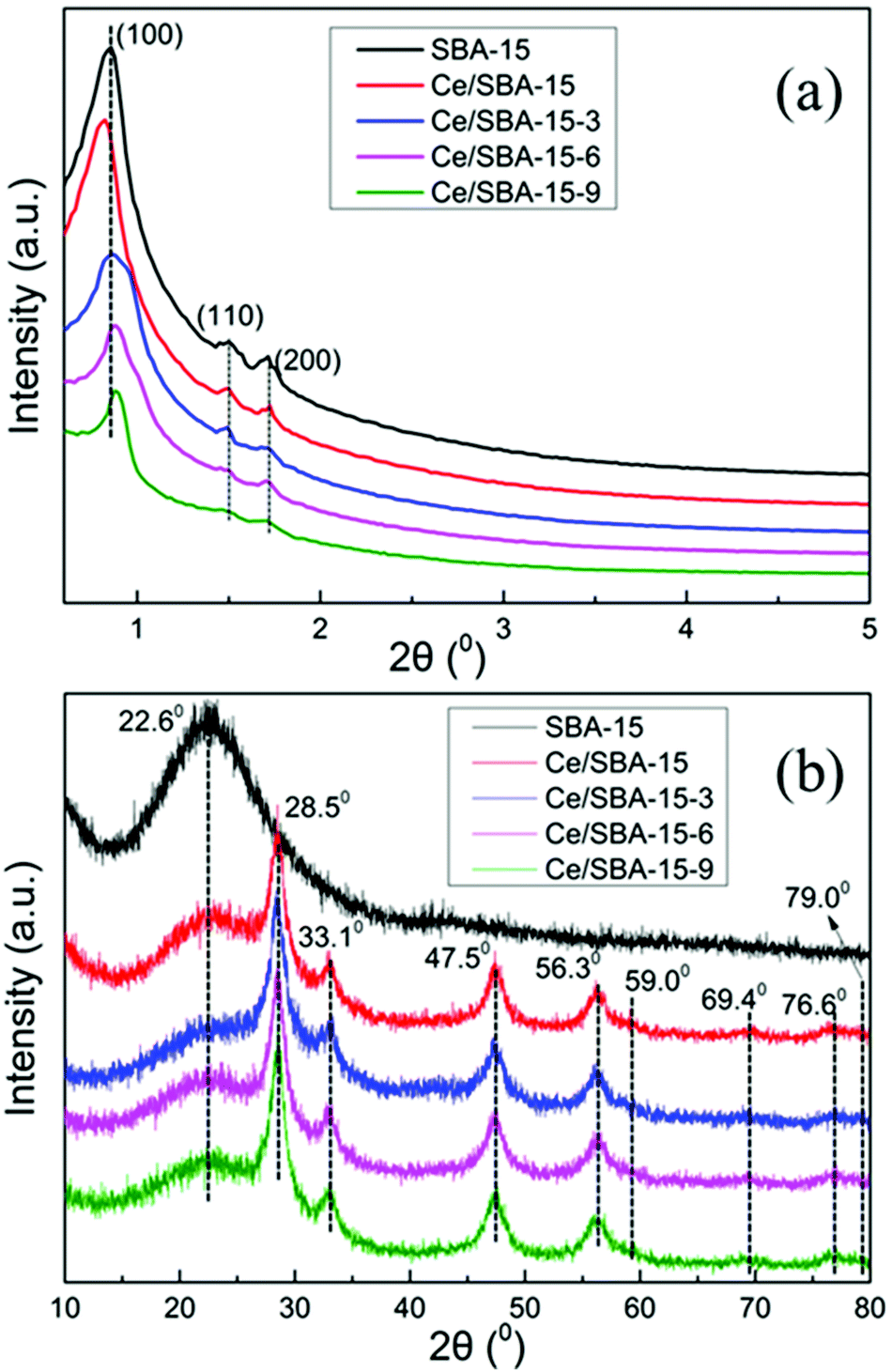 | ||
| Fig. 1 XRD patterns of SBA-15, Ce/SBA-15 and Ce/SBA-15-X (X = 3, 6, and 9) catalysts analyzed at low angle (a) and high angle (b). | ||
| Sample | Vp (cm3 g−1)a | SBET (m2 g−1)b | Dp (nm)c | ao (nm)d |
|---|---|---|---|---|
a Total pore volumes were obtained at P/Po = 0.99.b BET specific areas.c Average pore diameter calculated using the BJH method.d XRD unit-cell parameter calculated as 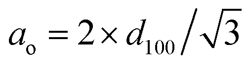 . . |
||||
| SBA-15 | 1.32 | 858 | 6.8 | 10.7 |
| Ce/SBA-15 | 1.24 | 844 | 6.7 | 10.7 |
| Ce/SBA-15-3 | 1.03 | 797 | 6.5 | 10.7 |
| Ce/SBA-15-6 | 0.98 | 794 | 6.4 | 10.8 |
| Ce/SBA-15-9 | 0.96 | 792 | 6.4 | 10.8 |
Fig. 1b shows the high-angle XRD patterns of the corresponding samples. The pattern of pure SBA-15 showed a broad diffraction peak at 2θ = 23°, which could be due to amorphous silica.51 Moreover, four cubic phases of CeO2 diffraction peaks were observed at 2θ = 28.5°, 33.1°, 47.5° and 56.3° for the Ce/SBA-15 catalyst,52 which could be due to the CeO2 (1 1 1), CeO2 (2 0 0), CeO2 (2 2 0) and CeO2 (3 1 1) planes, respectively (JCPDS 43-1002). Meanwhile, the weak diffraction peaks at 2θ = 59.0°, 69.4°, 76.6° and 79.0° could be assigned to the Ce2O3 (2 2 2), Ce2O3 (4 0 0), Ce2O3 (3 3 1), and Ce2O3 (4 2 0) planes, respectively (JCPDS. 78-0484). After grafting with –Si(CH3)3 groups, no clear change in the above eight diffraction peaks was detected, illustrating that the hydrophobic modification did not affect the structure of CeO2/Ce2O3 mixed oxide on the catalyst surface.
The N2 adsorption–desorption isotherms and pore-size distributions of the obtained mesoporous materials are shown in Fig. 2. The type IV isotherm curves with H1 hysteresis loops in Fig. 2a clearly indicate a mesoporous structure for all samples.53 The narrow and sharp pore size distribution curves (Fig. 2b) reveal the highly uniform pore size of the as-obtained mesoporous materials. The textural parameters of the mesoporous catalysts are summarized in Table 1. Compared with the results for pure SBA-15, the specific surface area (SBET), pore size (Dp) and pore volume (Vp) of the Ce/SBA-15 catalyst decreased slightly, whereas the unit-cell parameter (ao) increased; this may result from the incorporation of Ce into the SBA-15 framework due to the longer bond length of Ce–O than that of Si–O. Finally, no clear pore blockage is observed.54,55 Table 1 also shows that the amount of nitrogen adsorption decreases as the number of organic groups increases. Interestingly, the specific surface area and pore volume of the Ce/SBA-15-X (X = 3, 6, and 9) samples decrease in the following order: Ce/SBA-15 > Ce/SBA-15-3 > Ce/SBA-15-6 > Ce/SBA-15-9; the inverse order is observed in terms of ao, which confirms the presence of attached organic groups inside the pores.50 These results are also consistent with the results obtained from low-angle XRD.
 | ||
| Fig. 2 Nitrogen adsorption–desorption isotherms (a) and pore-size distribution (b) curves of the SBA-15, Ce/SBA-15 and Ce/SBA-15-X (X = 3, 6, and 9) catalysts. | ||
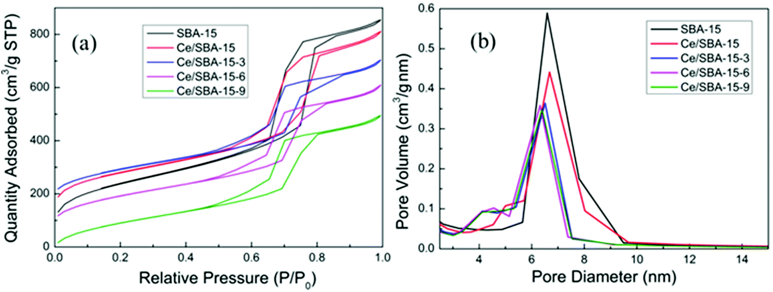
The FT-IR spectra of the samples are presented in Fig. 3. The bands at 1083, 804 and 465 cm−1 could be assigned to the asymmetric stretching, symmetric stretching and deformation vibrations of the Si–O–Si framework,56 respectively. Also, the band at 960 cm−1 could be ascribed to the Si–O stretching vibrations of the Si–OH group present in the SBA-15 framework.57
 | ||
| Fig. 3 FT-IR spectra of SBA-15, Ce/SBA-15 and Ce/SBA-15-X (X = 3, 6, and 9) catalysts. | ||
Upon loading Ce, the absorbance intensity of the peak at 960 cm−1 decreased, implying that the Si–OH groups had changed or transformed to Si–O–Ce.58 After grafting the hydrophobic –Si(CH3)3 groups, the absorbance intensity of the peak at 960 cm−1 further decreased as a result of the transformation of the Si–OH groups into Si–O–Si(CH3)3.59 The band at 3470 cm−1 was ascribed to the free Si–OH groups,60 whereas the other very sharp peak at around 1640 cm−1 could be assigned to the physically adsorbed water. Furthermore, new peaks appeared at 2963, 848 and 757 cm−1, which could be ascribed to the C–H stretching and Si–C stretching vibrations and CH3 rocking,61 respectively. These results suggested that the hydrophobic –Si(CH3)3 groups were successfully grafted on the silica framework of SBA-15.
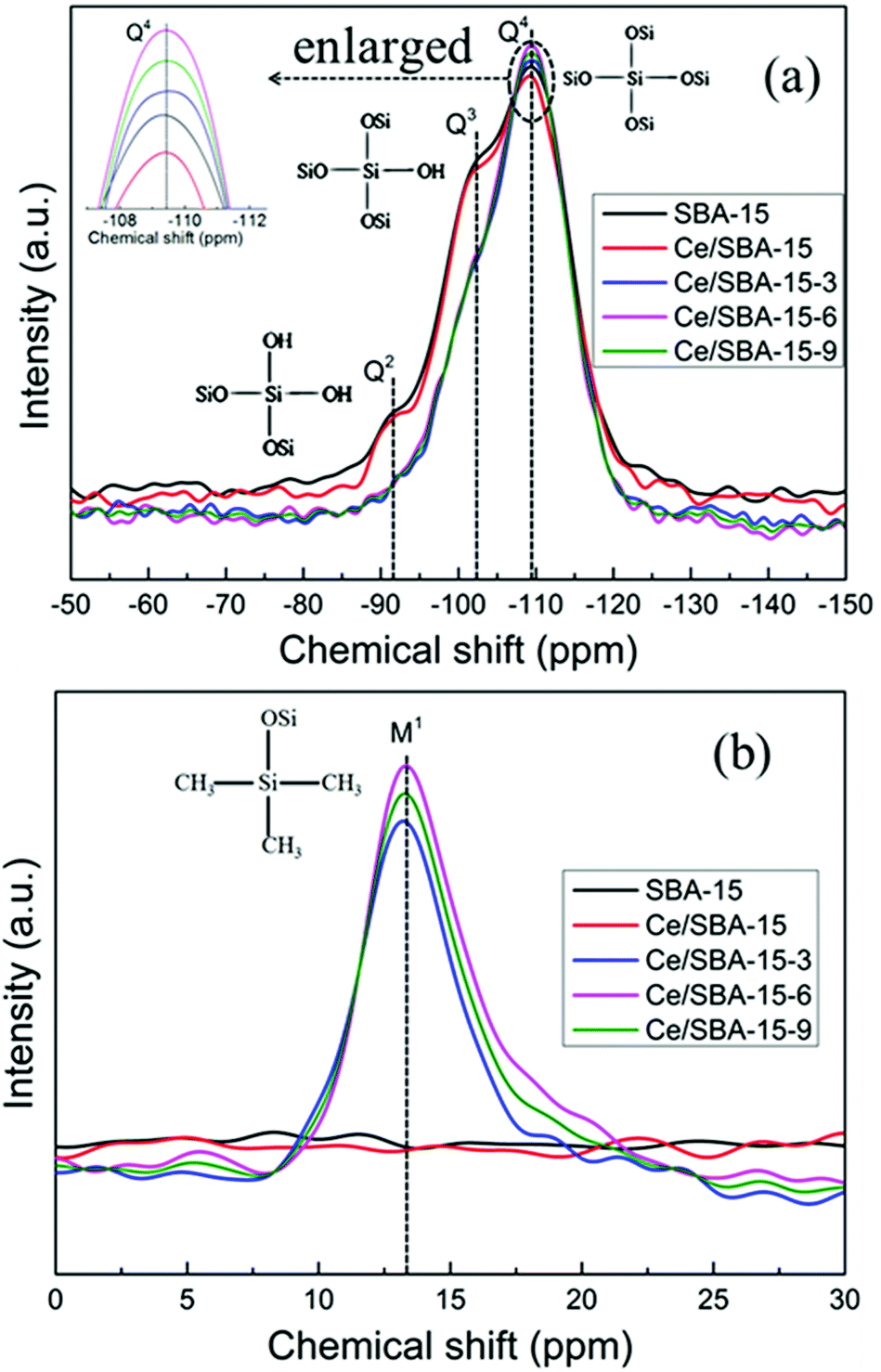
To quantify the degree of grafting on the SBA-15 framework, the catalysts were characterized via 29Si MAS NMR spectroscopy (Fig. 4). The peaks at −109.5, −102, and −91.5 ppm related to the Q4 [Si(OSi)4], Q3 [Si(OSi)3(OH)], and Q2 [Si(OSi)2(OH)2] units,62 respectively, were detected for SBA-15. After Ce loading, there was a small reduction in the intensities of the Q4, Q3 and Q2 species due to the fact that the Ce4+ species was strongly bonded to the mesoporous silica walls63 (Fig. 4a).
 | ||
| Fig. 4 29Si MAS NMR spectra of SBA-15, Ce/SBA-15 and Ce/SBA-15-X (X = 3, 6, and 9) catalysts. Q2, Q3 and Q4 (a); monofunctional sites M1 (b). | ||
After grafting with –Si(CH3)3 groups, new monofunctional M1 species (Fig. 4b) were detected at δ = 13 ppm for Ce/SBA-15-X (X = 3, 6, and 9) catalysts. Furthermore, with an increase in the amount of HMDS, the intensity of M1 bands (with respect to that of Q4 bands) gradually increased, and the resonance peaks for Q3 and Q2 units disappeared, which suggested that both types of surface silanol groups (Q3 and Q2) were consumed and converted to Q4 bands. These results also illustrated the successful condensation and grafting of the –Si(CH3)3 species onto the mesoporous SBA-15 walls. The amount of –Si(CH3)3 groups in the Ce/SBA-15-X (X = 3, 6, and 9) catalysts decreased in the order of Ce/SBA-15-6 > Ce/SBA-15-9 > Ce/SBA-15-3. It is worth noting that the Ce/SBA-15-9 catalyst involving the maximum addition of HMDS did not show the highest amount of hydrophobic functional –Si(CH3)3 groups. This may be because excess HMDS intensified the agglomeration of the SBA-15 powder and thus, it could not efficiently react with HMDS, which reduced the amount of grafted –Si(CH3)3 groups.
To further understand the effect of the amount of –Si(CH3)3 groups on hydrophobicity, detailed CA measurements were carried out, and the results are shown in Fig. 5. As shown, both the SBA-15 and the Ce/SBA-15 catalysts exhibited a small contact angle (below 90°), indicating the hydrophilic nature of the samples. Upon grafting of –Si(CH3)3 groups, the Ce/SBA-15-6 catalyst showed the largest contact angle of ∼132.5°, followed by Ce/SBA-15-9 (120.5°) and Ce/SBA-15-3 (109°). Combined with the 29Si MAS NMR spectra, it was inferred that the highest hydrophobicity could only be achieved through an optimum HMDS usage.
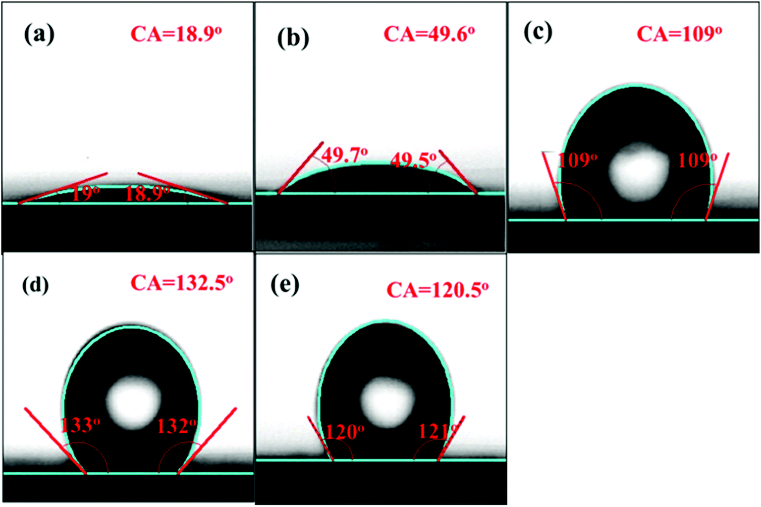 | ||
| Fig. 5 Contact angle images of SBA-15 (a), Ce/SBA-15 (b), Ce/SBA-15-3 (c), Ce/SBA-15-6 (d), and Ce/SBA-15-9 (e). | ||
The shape and surface morphology of the samples were investigated via TEM, and the results are depicted in Fig. 6. It can be seen that the SBA-15 (Fig. 6a) catalyst has a regular morphology and ordered structure; the hexagonal mesostructure was retained after loading with CeO2 (Fig. 6b) and further hydrophobic modification (Fig. 6c and d), which further confirmed the results of low-angle XRD and N2 adsorption–desorption. In addition, the average particle size of CeO2 was about 10.92 nm for the Ce/SBA-15 catalyst. After surface grafting, the average particle sizes were about 11.12 nm and 11.33 nm for Ce/SBA-15-6 (Fig. 6c) and Ce/SBA-15-9 (Fig. 6d) catalysts, respectively. This result suggested that the hydrophobic modification did not change the particle size of the catalyst. Meanwhile, the particle size of CeO2 obtained from TEM was clearly larger than the pore size of SBA-15 (Table 1), suggesting that CeO2 molecules were mainly distributed on the surface of SBA-15. According to the TEM results, we inferred that the particle size of CeO2 was slightly larger than that obtained from XRD (Table 1), which can be due to the aggregation of polycrystalline CeO2. Moreover, the HR-TEM images of Ce/SBA-15, Ce/SBA-15-6 and Ce/SBA-15-9 catalysts (Fig. S1†) revealed that all particles exhibited crystalline structures with d-spacings of 0.30 nm and 0.32 nm, corresponding to the (3 1 1) plane spacing of CeO2 and (2 2 2) plane spacing of Ce2O3. The presence of two species (CeO2 and Ce2O3) of Ce oxide further confirmed the results of high-angle XRD (Fig. 1b).
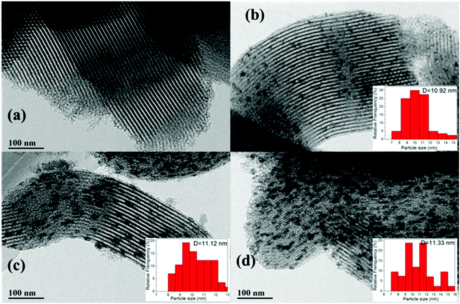 | ||
| Fig. 6 TEM images of SBA-15 (a), Ce/SBA-15 (b), Ce/SBA-15-6 (c), and Ce/SBA-15-9 (d). | ||
XPS spectra were obtained to determine cerium species and their relative amounts in Ce/SBA-15 and Ce/SBA-15-X (X = 3, 6, and 9) catalysts. Deconvolution of the Ce 3d profile was performed to discriminate the species (Fig. S2†) and determine the detailed content (Table 2). The structures labeled as v (882.2 ± 0.2 eV), v′′ (887.5 ± 0.3 eV), v′′′ (898.5 ± 0.4 eV), u (900.4 ± 0.4 eV), u′′ (905.7 ± 0.5 eV), and u′′′ (917.1 ± 0.3 eV) are characteristics of CeO2 (3d104f0 state of Ce4+), whereas v′ (885.5 ± 0.3 eV) and u′ (903.4 ± 0.4 eV) are associated with Ce2O3 (3d104f1 state of Ce3+).64 It was found that the Ce3+ content increased with an increase in HMDS, indicating that a valence transition from Ce4+ to Ce3+ might occur at higher hydrophobicity.
| Samples | Area%, binding energy (eV) | Ce4+ | Ce3+ | Ce3+/Ce4+ | |||||||
|---|---|---|---|---|---|---|---|---|---|---|---|
| Ce4+ | Ce3+ | ||||||||||
| v | u | v′′ | u′′ | v′′′ | u′′′ | v′ | u′ | ||||
| SBA-15 | — | — | — | — | — | — | — | — | — | — | — |
| Ce/SBA-15 | 19.43 | 10.45 | 12.27 | 4.12 | 14.91 | 6.67 | 13.96 | 18.19 | 67.85 | 32.15 | 0.47 |
| Ce/SBA-15-3 | 18.70 | 12.83 | 8.83 | 2.91 | 15.93 | 4.55 | 18.05 | 18.20 | 63.75 | 36.25 | 0.56 |
| Ce/SBA-15-6 | 16.26 | 13.71 | 3.10 | 8.09 | 10.26 | 7.49 | 23.21 | 17.88 | 58.91 | 41.09 | 0.69 |
| Ce/SBA-15-9 | 15.47 | 26.18 | 0.74 | 9.70 | 1.83 | 7.61 | 25.50 | 12.97 | 61.53 | 38.47 | 0.62 |
| Samples | Area%, binding energy (eV) | |||||||
|---|---|---|---|---|---|---|---|---|
| Ce4+ | Ce3+ | |||||||
| v | u | v′′ | u′′ | v′′′ | u′′′ | v′ | u′ | |
| SBA-15 | — | — | — | — | — | — | — | — |
| Ce/SBA-15 | 882.2 | 900.9 | 887.3 | 905.9 | 898.5 | 917.1 | 885.3 | 903.6 |
| Ce/SBA-15-3 | 882.1 | 900.9 | 887.9 | 905.8 | 898.9 | 917.0 | 885.4 | 903.9 |
| Ce/SBA-15-6 | 882.4 | 900.8 | 887.5 | 905.0 | 898.6 | 917.3 | 885.5 | 903.1 |
| Ce/SBA-15-9 | 882.1 | 900.0 | 887.8 | 905.1 | 898.1 | 917.0 | 885.9 | 903.0 |
Meanwhile, to achieve charge balance, oxygen vacancies were introduced into the lattice during the process of valence transition from Ce4+ to Ce3+.65 As shown in Table 2, the Ce/SBA-15-6 catalyst exhibited the highest Ce3+/Ce4+ molar ratio of 0.69. However, with the addition of more HDMS, the molar ratio of Ce3+/Ce4+ decreased to 0.62 for Ce/SBA-15-9. Combined with the results of 29Si MAS NMR (Fig. 4) and contact angle (Fig. 5), it was easy to conclude that the Ce/SBA-15-6 catalyst has the highest concentration of oxygen vacancies due to its highest hydrophobicity. This result was consistent with the observations of Souza et al.;45 they concluded that the oxygen vacancy content in CeO2 electrodeposits determines the hydrophobicity, and the oxygen vacancy content in CeO2 can be effectively tuned by adjusting the strength of hydrophobicity.
This result was also supported by the O 1s spectra (Fig. S3†); the peak at 532.7 eV was assigned to the surface hydroxyl groups (Si–OH) in SBA-15, whereas the peak at ∼532 eV was assigned to the oxygen vacancies or defects on the surface of CeO2.64,66 The other peak at a binding energy of 533.5 eV was due to adsorbed H2O species.67 It was clearly observed that the main peak position gradually shifted from 532.7 eV for SBA-15 to a lower binding energy (∼532 eV) with the addition of an increasing amount of HMDS, illustrating the transition of oxygen species from surface hydroxyl to oxygen vacancies. This result also indicated that the concentration of oxygen vacancies increased with the increase in hydrophobicity.
NH3-TPD experiments were performed to characterize the acidities of different samples, and the results are shown in Fig. 7. Only one large desorption peak of NH3 near 93 °C emerged for SBA-15, which could be ascribed to the weak acidic sites.68 There was also one NH3 desorption peak at around 88 °C for the CeO2 catalyst, which was similar to the results obtained by Keiichi Tomishige.69 After loading cerium, the Ce/SBA-15 catalyst showed two small peaks at approximately 80 °C and 250 °C, which could be ascribed to the weak (50–200 °C) and moderate (200–400 °C) acidic sites, respectively. However, for the Ce/SBA-15-X (X = 3, 6, and 9) catalysts, the two peaks corresponding to weak and moderate acidic sites moved to higher temperatures, which might be due to the fact that hydrophobic groups increase the diffusion resistance of NH3.
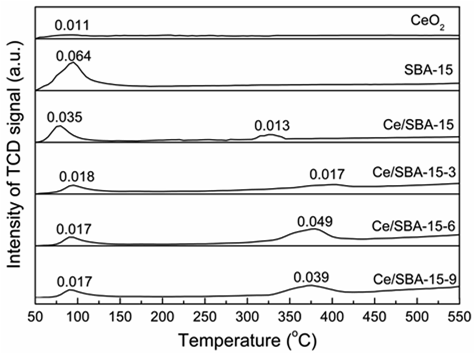 | ||
| Fig. 7 NH3-TPD profiles of CeO2, SBA-15, Ce/SBA-15 and Ce/SBA-15-X (X = 3, 6, and 9) catalysts. Adsorption amount of NH3 was measured by volumetric methods, with the unit of mmol gcat−1. | ||
The total amounts of NH3 desorbed from the catalysts were measured via volumetric methods, and the results are presented in Fig. 7. The Ce/SBA-15-6 catalyst exhibited the highest amount of desorbed NH3 (0.049 mmol gcat−1), which indicated the largest amount of moderate Lewis acidic sites resulting from oxygen vacancies on the metal-oxide interface.70 The changes in the amount of moderate Lewis acidic sites followed the same trend as that of the concentration of oxygen vacancies, i.e., a higher concentration of oxygen vacancies leads to a larger amount of moderate Lewis acidic sites.
CO2-TPD experiments were performed to characterize the basicities of different samples. The result curves and the detailed amount of basic sites are shown in Fig. S4.† No desorption of CO2 was observed over SBA-15, which was in agreement with the fact that SBA-15 does not have basic sites. In addition, only one desorption peak of CO2 at a maximum temperature of ca. 90 °C emerged for the CeO2 catalyst. Meanwhile, the amount of desorbed CO2 was 0.027 mmol gcat−1, which was lower than that for the CeO2 catalyst (0.067 mmol gcat−1), as reported by Keiichi Tomishige.69 For the Ce/SBA-15 catalyst, three weak peaks corresponding to weak (50–150 °C), moderate (150–350 °C) and strong (>350 °C) basic sites were observed. However, for the silylated Ce/SBA-15-X (X = 3, 6, and 9) catalysts, weak basic sites assigned to hydroxyl groups (OH−) of Ce–OH disappeared, as they may have been consumed or transformed into Ce–O–Si bonds through the hydrolysis–condensation reaction. Meanwhile, moderate and strong basic sites of the Ce/SBA-15-X (X = 3, 6, and 9) catalysts derived from Ce–O pairs and O2− anions were formed, which exhibited similar peak positions and amount of CO2 desorption, indicating that the introduction of HMDS has negligible effect on the basic sites of the as-prepared Ce/SBA-15-X (X = 3, 6, and 9) catalysts.
3.2 Catalytic behavior
The performance of Ce/SBA-15-X (X = 3, 6, and 9) catalysts for the direct synthesis of DMC from CO2 and methanol is shown in Table 3. For all the catalysts, the selectivity to DMC was estimated to be 100% because the amounts of expected byproducts (DME and CO) were below the detection limit (not shown here). The results showed that no DMC formation was observed on the pure SBA-15 support. After Ce loading, the DMC yield increased to 0.075% for the Ce/SBA-15 catalyst. Upon introduction of trimethylsilyl (TMS) groups, the catalytic activity further increased. The DMC yield reached a maximum value of 0.19% (reaction time: 10 h) over Ce/SBA-15-6 and then decreased to 0.17% for Ce/SBA-15-9, suggesting that hydrophobic modification is beneficial for the formation of DMC. In addition, the equilibrium level of DMC formation over the Ce/SBA-15-6 and Ce/SBA-15-9 catalysts was also determined, as shown in Fig. S5.† The results showed that both catalysts could achieve the same equilibrium yield of 0.2%, and the more active Ce/SBA-15-6 catalyst required shorter reaction time to reach equilibrium. Meanwhile, the amounts of catalysts did not affect the equilibrium yield of DMC (Fig. S6†) under the same reaction conditions. According to the simulation results reported by Kabra et al.,71 the equilibrium yield of DMC was 0.23% under the reaction conditions of 125 °C, 10 MPa and CH3OH/CO2 ratio of 2:1. In the present study, the Ce/SBA-15-6 catalyst showed a maximum DMC yield of 0.20% under the reaction conditions of 130 °C, 10 MPa and CH3OH/CO2 ratio of 2:1. Thus, it was suggested that hydrophobic catalysts have good catalytic activities for the formation of DMC.
| Catalyst | Reaction conditions | Ref. | ||||
|---|---|---|---|---|---|---|
| Temperature (°C) | Initial pressure (MPa) | Reaction time (h) | Catalyst weight (g) | DMC yield (%) | ||
| SBA-15 | 130 | 5 | 10 | 0.5 | 0 | This work |
| CeO2 | 130 | 5 | 10 | 0.05 | 0.035 | This work |
| Ce/SBA-15 | 130 | 5 | 10 | 0.5 | 0.075 | This work |
| Ce/SBA-15-3 | 130 | 5 | 10 | 0.5 | 0.135 | This work |
| Ce/SBA-15-6 | 130 | 5 | 10 | 0.5 | 0.19 | This work |
| Ce/SBA-15-9 | 130 | 5 | 10 | 0.5 | 0.17 | This work |
| Ce-SBA-15-6 | 130 | 5 | 10 | 0.5 | 0.035 | This work |
| CeO2 | 130 | 5 | 2 | 0.05 | 0.01 | This work |
| Ce/SBA-15-6 | 130 | 5 | 2 | 0.5 | 0.075 | This work |
| CeO2 | 110 | 5 | 2 | 0.01 | 0.05 | 26 |
| CeO2 | 120 | 5 | 1 | 0.01 | 0.024 | 29 |
To assess the relationship between catalytic activity and dehydration capability, the mechanically mixed Ce-SBA-15-6 catalyst (0.05 g CeO2 + 0.45 g SBA-15-6) was also tested for the direct synthesis of DMC from CO2 and methanol (Table 3). The Ce-SBA-15-6 catalyst exhibited a DMC yield of 0.035%, which was much lower than that over Ce/SBA-15-6 (0.19%), suggesting the low effect of the hydrophobic groups on the DMC yield by mechanical mixing of CeO2 and hydrophobic SBA-15-6 support.
In addition, a comparison of previously reported catalysts and our catalysts was carried out, and the results are also shown in Table 3. According to the results reported by Masayoshi Honda, the DMC yield was 0.024% over the CeO2 catalyst (0.01 g) with a reaction time of 1 h.29 However, in the present study, the CeO2 catalyst (0.05 g) had a DMC yield of 0.01% with a reaction time of 2 h. Meanwhile, the Ce/SBA-15-6 catalyst with the same amount of CeO2 (0.05 g) showed a DMC yield of 0.075% under the same reaction conditions. These results suggested that the amounts of DMC formed in this study were reasonable and credible under our reaction conditions.
Finally, the catalytic stability of Ce/SBA-15-6 was also examined (Fig. S7†). The catalyst was recovered by washing with methanol several times and drying at 150 °C for 12 h and then, it was reused for another cycle. It was observed that the DMC yield was virtually stable during all recycling experiments, suggesting the high stability of the Ce/SBA-15-6 catalyst.
3.3 The effect of acidity-basicity on the catalytic activity
It is well-known that the acid sites of a catalyst play an important role in the activation of CH3OH to CH3+,72 which may be the rate-determining step in the formation of DMC from methanol and carbon dioxide.73,74 Among the catalysts tested, SBA-15 with the largest amount of weak acidic sites (0.064 mmol gcat−1) showed no activity for DMC formation, implying that weak acid sites cannot activate methanol.68 After Ce loading, moderate acid sites appeared, and the DMC yield increased. Upon grafting of trimethylsilyl (TMS) groups, the Ce/SBA-15-6 catalyst with the largest amount of moderate acidic sites (0.049 mmol gcat−1) showed a maximum DMC yield of 0.19%, and the DMC yields over the Ce/SBA-15-X (X = 3, 6, and 9) catalysts increased with an increase in the amount of moderate acid sites. These results indicated that the amount of moderate acidic sites is the most important factor while determining the catalytic activity.The CO2-TPD results (Fig. S4†) combined with the catalytic performance (Table 3) revealed that despite similar CO2 desorption peak positions and areas, the hydrophobic Ce/SBA-15-X (X = 3, 6, and 9) catalysts showed different DMC yields, suggesting that the basic sites have a smaller impact than the acidic sites on catalytic activity. These results were consistent with those reported by Jiang et al.,74 where the activation of CH3OH to CH3+ on acidic sites may be the rate-determining step in the formation of DMC.
3.4 The effect of hydrophobicity on catalytic activity
Apart from moderate acid sites, the hydrophobicity of the catalyst also affects its catalytic behavior, i.e., despite similar amounts of moderate acid sites (0.017 mmol gcat−1 and 0.013 mmol gcat−1), the hydrophobic Ce/SBA-15-3 catalyst exhibited a higher DMC yield (0.135%) than the hydrophilic Ce/SBA-15 catalyst (0.075%). This means that the catalytic activity is not only related to the amount of moderate acid sites, but also to hydrophobicity. Compared with the mechanically mixed Ce-SBA-15-6, the Ce/SBA-15-6 catalyst showed enhanced catalytic activity, indicating that the combination of active sites and hydrophobic groups also affects catalytic activity; only the chemical combination of the hydrophobic groups and CeO2 can realize maximum interaction between catalytic activity and dehydration capability, which favors the removal of the water byproduct.443.5 A discussion of the reaction mechanism
Based on previous researches22,24,29,75 and the results in this study, a possible reaction mechanism for the synthesis of DMC from CO2 with methanol is proposed and depicted in Fig. 8. One molecule of methanol was activated to form methoxy species on the basic sites of CeO2. Then, carbon dioxide reacted with the methoxy species to form the methoxy carbonate anion as an intermediate. Finally, the intermediate further reacted with the methyl species generated on the acid sites to produce DMC. For this reaction, the oxygen vacancies either acted as Lewis acid sites or enhanced the strength of Lewis acid sites on the CeO2 catalyst, which could activate CH3OH to form CH3+. The higher the acidity of the catalyst, the more positive the charge on CH3+, which easily promoted the formation of DMC. Meanwhile, the hydrophobic groups could enhance the removal of water and reduce the adsorbed water on the surface, thus shortening the reaction time.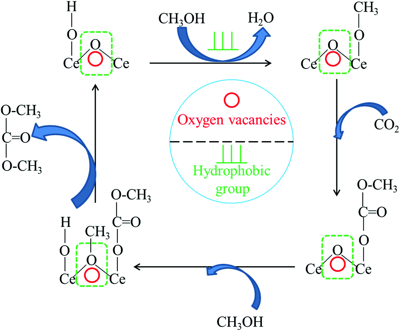 | ||
| Fig. 8 Proposed reaction scheme of DMC synthesis from CO2 and methanol over hydrophobic Ce/SBA-15 catalysts. | ||
4. Conclusion
Hydrophobic Ce/SBA-15 catalysts were prepared via the post-grafting method using HMDS as a modified solvent, and they showed better catalytic performances than hydrophilic catalysts for the direct synthesis of dimethyl carbonate from CO2 and methanol. The hydrophobicity of the catalysts facilitated the creation of oxygen vacancies on CeO2, which then acted as Lewis acids to activate methanol. The amount of moderate acidic sites on the catalyst played an important role in determining the catalytic performance. Furthermore, the hydrophobicity of the catalyst could reduce the deactivation of active sites by removing water, thus shortening the reaction time.Conflicts of interest
There are no conflicts to declare.Acknowledgements
This work was financially supported by the Science Foundation for Young Scientists of Shanxi Province, China (Grant No. 201701D221052), Independent Research Project of the State Key Laboratory of Coal Conversion (2018BWZ002), Natural Science Foundation of Shanxi Province (No. 201601D102006) and the Key Science and Technology Program of Shanxi Province, China (MD2014-09, MD2014-10).References
- N. Keller, G. Rebmann and V. Keller, J. Mol. Catal. A: Chem., 2010, 317, 1–18 CrossRef.
- Y. Li, X. Q. Zhao and Y. J. Wang, Appl. Catal., A, 2005, 279, 205–208 CrossRef.
- J. Bian, M. Xiao, S. J. Wang, Y. X. Lu and Y. Z. Meng, Catal. Commun., 2009, 10, 1142–1145 CrossRef.
- Y. Ono, Appl. Catal., A, 1997, 155, 133–166 CrossRef.
- Z. F. Zhang, Z. W. Liu, J. Lu and Z. T. Liu, Ind. Eng. Chem. Res., 2011, 50, 1981–1988 CrossRef.
- S. Y. Huang, B. Yan, S. P. Wang and X. B. Ma, Chem. Soc. Rev., 2015, 44, 3079–3116 RSC.
- R. Saada, S. Kellici, T. Heil, D. Morgan and B. Saha, Appl. Catal., B, 2015, 168–169, 353–362 CrossRef.
- M. Honda, M. Tamura, Y. Nakagawa and K. Tomishige, Catal. Sci. Technol., 2014, 4, 2830–2845 RSC.
- B. A. V. Santos, V. M. T. M. Silva, J. M. Loureiro and A. E. Rodrigues, ChemBioEng Rev., 2014, 1(5), 214–229 CrossRef.
- E. Leino, P. Mäki-Arvela, V. Eta, D. Y. Murzin, T. Salmi and J. P. Mikkola, Appl. Catal., A, 2010, 383, 1–13 CrossRef.
- T. Sakakura, J. C. Choi, Y. Saito and T. Sako, Polyhedron, 2000, 19, 573–576 CrossRef.
- T. S. Zhao, Y. Z. Han and Y. H. Sun, Fuel Process. Technol., 2000, 62, 187–194 CrossRef.
- Q. H. Cai, B. Lu, L. J. Guo and Y. K. Shan, Catal. Commun., 2009, 10, 605–609 CrossRef.
- S. Fang and K. Fujimoto, Appl. Catal., A, 1996, 142, L1–L3 CrossRef.
- X. L. Wu, Y. Z. Meng, M. Xiao and Y. X. Lu, J. Mol. Catal. A: Chem., 2006, 249, 93–97 CrossRef.
- X. J. Wang, M. Xiao, S. J. Wang, Y. X. Lu and Y. Z. Meng, J. Mol. Catal. A: Chem., 2007, 278, 92–96 CrossRef.
- J. Bian, M. Xiao, S. J. Wang, X. J. Wang, Y. X. Lu and Y. Z. Meng, Chem. Eng. J., 2009, 147, 287–296 CrossRef.
- J. Bian, M. Xiao, S. J. Wang, Y. X. Lu and Y. Z. Meng, Catal. Commun., 2009, 10, 1529–1533 CrossRef.
- J. Bian, M. Xiao, S. J. Wang, Y. X. Lu and Y. Z. Meng, Appl. Surf. Sci., 2009, 255, 7188–7196 CrossRef.
- Y. J. Zhou, M. Xiao, S. J. Wang, D. M. Han, Y. X. Lu and Y. Z. Meng, Chin. Chem. Lett., 2013, 24, 307–310 CrossRef.
- Y. J. Zhou, S. J. Wang, M. Xiao, D. M. Han, Y. X. Lu and Y. Z. Meng, RSC Adv., 2012, 2, 6831–6837 RSC.
- K. Tomishige, Y. Ikeda, T. Sakaihori and K. Fujimoto, J. Catal., 2000, 192, 355–362 CrossRef.
- K. Tomishige, T. Sakaihori, Y. Ikeda and K. Fujimoto, Catal. Lett., 1999, 58, 225–229 CrossRef.
- M. Aresta, A. Dibenedetto, C. Pastore, A. Angelini, B. Aresta and I. Pápai, J. Catal., 2010, 269, 44–52 CrossRef.
- M. Aresta, A. Dibenedetto, C. Pastore, C. Cuocci, B. Aresta, S. Cometa and E. D. Giglio, Catal. Today, 2008, 137, 125–131 CrossRef.
- Y. Yoshida, Y. Arai, S. Kado, K. Kunimori and K. Tomishige, Catal. Today, 2006, 115, 95–101 CrossRef.
- S. P. Wang, L. F. Zhao, W. Wang, Y. J. Zhao, G. L. Zhang, X. B. Ma and J. L. Gong, Nanoscale, 2013, 5, 5582–5588 RSC.
- X. L. Wu, M. Xiao, Y. Z. Meng and Y. X. Lu, J. Mol. Catal. A: Chem., 2005, 238, 158–162 CrossRef.
- M. Honda, M. Tamura, Y. Nakagawa, K. Nakao, K. Suzuki and K. Tomishige, J. Catal., 2014, 318, 95–107 CrossRef.
- M. Honda, M. Tamura, Y. Nakagawa, S. Sonehara, K. Suzuki, K. Fujimoto and K. Tomishige, ChemSusChem, 2013, 6, 1341–1344 CrossRef PubMed.
- M. Honda, A. Suzuki, B. Noorjahan, K. Fujimoto, K. Suzuki and K. Tomishige, Chem. Commun., 2009, 4596, 4596–4598 RSC.
- M. Honda, S. Kuno, N. Begum, K. Fujimoto, K. Suzuki, Y. Nakagawa and K. Tomishige, Appl. Catal., A, 2010, 384, 165–170 CrossRef.
- K. Tomishige and K. Kunimori, Appl. Catal., A, 2002, 237, 103–109 CrossRef.
- M. Tamura, K. Ito, M. Honda, Y. Nakagawa, H. Sugimoto and K. Tomishige, Sci. Rep., 2016, 6, 24038–24046 CrossRef PubMed.
- M. Tamura, K. Ito, Y. Nakagawa and K. Tomishige, J. Catal., 2016, 343, 75–85 CrossRef.
- M. Honda, M. Tamura, K. Nakao, K. Suzuki, Y. Nakagawa and K. Tomishige, ACS Catal., 2014, 4, 1893–1896 CrossRef.
- M. Tamura, M. Honda, Y. Nakagawa and K. Tomishige, J. Chem. Technol. Biotechnol., 2014, 89, 19–33 CrossRef.
- M. Tamura, K. Noro, M. Honda, Y. Nakagawa and K. Tomishige, Green Chem., 2013, 15, 1567–1577 RSC.
- M. Tamura, M. Honda, K. Noro, Y. Nakagawa and K. Tomishige, J. Catal., 2013, 305, 191–203 CrossRef.
- M. Honda, S. Sonehara, H. Yasuda, Y. Nakagawa and K. Tomishige, Green Chem., 2011, 13, 3406–3413 RSC.
- K. Tomishige, H. Yasuda, Y. Yoshida, M. Nurunnabi, B. T. Li and K. Kunimori, Catal. Lett., 2004, 95, 45–49 CrossRef.
- A. H. Tamboli, A. A. Chaugule and H. Kim, Chem. Eng. J., 2017, 323, 530–544 CrossRef.
- Y. X. Cao, H. X. Cheng, L. L. Ma, F. Liu and Z. M. Liu, Catal. Surv. Asia, 2012, 16, 138–147 CrossRef.
- P. B. Zhang, Y. Zhou, M. M. Fan, P. P. Jiang, X. L. Huang and J. Lou, Catal. Lett., 2013, 144, 320–324 CrossRef.
- J. C. Souza, I. T. Neckel, J. Varalda, E. Ribeiro, W. H. Schreiner, D. H. Mosca, M. R. Sierakowski, V. Fernandes and A. Ouerghi, J. Colloid Interface Sci., 2015, 441, 71–77 CrossRef PubMed.
- E. G. Moschetta, M. A. Sakwa-Novak, J. L. Greenfield and C. W. Jones, Langmuir, 2015, 31, 2218–2227 CrossRef PubMed.
- P. Kaminski and M. Ziolek, J. Catal., 2014, 312, 249–262 CrossRef.
- D. Y. Zhao, J. L. Feng, Q. S. Huo, N. Melosh, G. H. Fredrickson, B. F. Chmelka and G. D. Stucky, Science, 1998, 279, 548–552 CrossRef PubMed.
- S. C. Laha, P. Mukherjee, S. R. Sainkar and R. Kumar, J. Catal., 2002, 207, 213–223 CrossRef.
- T. X. Bui, S. Y. Kang, S. H. Lee and H. Choi, J. Hazard. Mater., 2011, 193, 156–163 CrossRef PubMed.
- N. Wang, W. Chu, T. Zhang and X. S. Zhao, Int. J. Hydrogen Energy, 2012, 37, 19–30 CrossRef.
- L. L. Li, L. Zhang, K. Ma, W. X. Zou, Y. Cao, Y. Xiong, C. J. Tang and L. Dong, J. Chem. Technol. Biotechnol., 2017, 207, 366–375 Search PubMed.
- D. Y. Zhao, Q. S. Huo, J. L. Feng, B. F. Chmelka and G. D. Stucky, J. Am. Chem. Soc., 1998, 120, 6024–6036 CrossRef.
- X. G. Zhao, J. L. Shi, B. Hu, L. X. Zhang and Z. L. Hua, Mater. Lett., 2004, 58, 2152–2156 CrossRef.
- S. Y. Chen, J. F. Lee and S. Cheng, J. Catal., 2010, 270, 196–205 CrossRef.
- C. T. Kirk, Phys. Rev. B, 1988, 38, 1255–1273 CrossRef.
- L. Bois, A. Bonhommé, A. Ribes, B. Pais, G. Raffin and F. Tessier, Colloids Surf., A, 2003, 221, 221–230 CrossRef.
- P. Biswas, P. Narayanasarma, C. M. Kotikalapudi, A. K. Dalai and J. Adjaye, Ind. Eng. Chem. Res., 2011, 50, 7882–7895 CrossRef.
- L. H. Jia, L. T. Jia, D. B. Li, B. Hou, J. G. Wang and Y. H. Sun, J. Solid State Chem., 2011, 184, 488–493 CrossRef.
- J. S. Chen, Q. H. Li, R. R. Xu and F. S. Xiao, Angew. Chem., Int. Ed. Engl., 1995, 34, 2694–2696 CrossRef.
- A. J. V. Roosmalen and J. C. Mol, J. Phys. Chem., 1978, 82, 2748–2751 CrossRef.
- J. Alauzun, A. Mehdi, C. Reyé and R. J. P. Corriu, J. Mater. Chem., 2007, 17, 349–356 RSC.
- M. Selvaraj, D. W. Park and C. S. Ha, Microporous Mesoporous Mater., 2011, 138, 94–101 CrossRef.
- D. W. Jeong, W. J. Jang, H. S. Na, J. O. Shim, A. Jha and H. S. Roh, J. Ind. Eng. Chem., 2015, 27, 35–39 CrossRef.
- J. O. Shim, H. S. Na, A. Jha, W. J. Jang, D. W. Jeong, I. W. Nah, B. H. Jeong and H.-S. Roh, Chem. Eng. J., 2016, 306, 908–915 CrossRef.
- D. Jiang, W. Z. Wang, L. Zhang, Y. L. Zheng and Z. Wang, ACS Catal., 2015, 5, 4851–4858 CrossRef.
- L. Óvári, S. Krick Calderon, Y. Lykhach, J. Libuda, A. Erdőhelyi, C. Papp, J. Kiss and H. P. Steinrück, J. Catal., 2013, 307, 132–139 CrossRef.
- L. Chmielarz, P. Kustrowski, M. Kruszec and R. Dziembaj, J. Porous Mater., 2005, 12, 183–191 CrossRef.
- K. Tomishige, H. Yasuda, Y. Yoshida, M. Nurunnabi, B. T. Li and K. Kunimori, Green Chem., 2004, 6, 206–214 RSC.
- A. Auroux and A. Gervasini, J. Phys. Chem., 1990, 94, 6371–6379 CrossRef.
- S. K. Kabra, E. Turpeinen, R. L. Keiski and G. D. Yadav, J. Supercrit. Fluids, 2016, 117, 98–107 CrossRef.
- H. J. Lee, S. Park, I. K. Song and J. C. Jung, Catal. Lett., 2011, 141, 531–537 CrossRef.
- Y. Ikeda, M. Asadullah, K. Fujimoto and K. Tomishige, J. Phys. Chem. B, 2001, 105, 10653–10658 CrossRef.
- C. J. Jiang, Y. H. Guo, C. G. Wang, C. W. Hu, Y. Wu and E. B. Wang, Appl. Catal., A, 2003, 256, 203–212 CrossRef.
- K. T. Jung and A. T. Bell, J. Catal., 2001, 204, 339–347 CrossRef.
Footnote |
| † Electronic supplementary information (ESI) available. See DOI: 10.1039/c8ra04028a |
| This journal is © The Royal Society of Chemistry 2018 |