 Open Access Article
Creative Commons Attribution 3.0 Unported Licence
High performance sol–gel synthesized Ce0.9Sr0.1(Zr0.53Ti0.47)O4 sensing membrane for a solid-state pH sensor
Sankar Prasad Baga,
Prabir Garua,
Jim-Long Herb,
Bih-Show Loucd and
Tung-Ming Pan *ae
*ae
aDepartment of Electronics Engineering, Chang Gung University, Taoyuan 33302, Taiwan. E-mail: tmpan@mail.cgu.edu.tw; Fax: +886-3-2118507; Tel: +886-3-2118800 ext. 3349
bDivision of Natural Science, Center for General Education, Chang Gung University, Taoyuan 33302, Taiwan
cChemistry Division, Center for General Education, Chang Gung University, Taoyuan 33302, Taiwan
dDepartment of Nuclear Medicine and Molecular Imaging Center, Chang Gung Memorial Hospital, Taoyuan 33302, Taiwan
eDivision of Urology, Chang Gung Memorial Hospital, Taoyuan 33302, Taiwan
First published on 11th June 2018
Abstract
In this paper, we developed a high-performance solid-state pH sensor using a Ce0.9Sr0.1(Zr0.53Ti0.47)O4 (CSZT) membrane through a very simple sol–gel spin-coating process. The structural properties of the CSZT membrane are correlated with its sensing characteristics. The CSZT based EIS sensor exhibited a high pH sensitivity of 92.48 mV pH−1, which is beyond the Nernst limit (59.4 mV pH−1), and good reliability in terms of a low hysteresis voltage of 1 mV and a small drift rate of 0.15 mV h−1. This behaviour is attributed to the incorporation of Sr in the CSZT sensing membrane, which promotes change in the Ce oxidation state from Ce4+ to Ce3+.
Introduction
Determination of pH value is one of the most important measurements in all pH dependent chemical processes, especially in agricultural development, biochemical technology, the pharmaceutical industry, and corrosion control areas.1 Currently, the most often used electrode is a traditional glass-membrane pH electrode due to its Nernstian response and low sensitivity to interfering species.2 However glass electrodes have two main problems, namely the fragility of the glass membrane and easy fouling in aggressive electrolytes. Substantial progress has been recently made towards integrating high-κ dielectric materials into electrolyte–insulator–semiconductor (EIS) sensors due to their high sensing performance.3–5 EIS-based solid-state sensors, e.g. ion-sensitive field-effect transistors (ISFETs),3 light-addressable potentiometric sensors (LAPs),6 and organic thin-film transistors (OTFTs),7 have attracted intense interest in recent decades due to their simple structure, low cost, and easy fabrication process. The gate insulator plays the most important role in an EIS device because this insulating membrane is directly placed in an aqueous solution. The accumulated charges at the surface of the gate oxide film that arise from the electrolyte solution cannot be passed through the film, thus leading to the change in the channel conductance and current modulation.4Different kinds of high-κ dielectric material, such as Al2O3, ZrO2, HfO2, Ta2O5, TiO2, and Y2O3,5,8–11 have been recently studied as sensing films in ISFET or EIS devices. Nevertheless, these materials can easily be reacted with Si substrates to form a silicate layer at the interface of the oxide film–Si substrate, thus degrading their electrical performance.12 To improve the electrical properties, rare-earth (RE) oxide film materials, including CeO2, Pr2O3, Gd2O3, and Yb2O3, have been investigated for use in complementary metal–oxide–semiconductor (CMOS), non-volatile memory, and EIS devices.13–15 However, moisture absorption is a major issue when RE oxides are used as gate dielectrics in CMOS devices, which degrades their electrical performance due to the formation of hydroxides.16 To avoid the unwanted hydroxide film, the Zr/Ti ratio of 0.53/0.47 was previously successfully adopted in a sensing film by our group.17 In this letter, we report the development of a high-performance Ce0.9Sr0.1(Zr0.53Ti0.47)O4 (CSZT) sensing membrane through a spin-coating process for a solid-state pH sensor, which is far beyond the Nernst limit of 59.4 mV pH−1 at 25 °C.
Experimental
The CSZT mixed oxide membrane was synthesized with 1 N HNO3 and CH3COOH via a simple sol–gel method. The cerium acetate hydrate, strontium nitrate, zirconium propoxide, and titanium isopropoxide were mixed according to the molar ratio of Ce![[thin space (1/6-em)]](https://www.rsc.org/images/entities/char_2009.gif) :
:![[thin space (1/6-em)]](https://www.rsc.org/images/entities/char_2009.gif) Sr
Sr![[thin space (1/6-em)]](https://www.rsc.org/images/entities/char_2009.gif) :
:![[thin space (1/6-em)]](https://www.rsc.org/images/entities/char_2009.gif) Zr
Zr![[thin space (1/6-em)]](https://www.rsc.org/images/entities/char_2009.gif) :
:![[thin space (1/6-em)]](https://www.rsc.org/images/entities/char_2009.gif) Ti = 0.9
Ti = 0.9![[thin space (1/6-em)]](https://www.rsc.org/images/entities/char_2009.gif) :
:![[thin space (1/6-em)]](https://www.rsc.org/images/entities/char_2009.gif) 0.1
0.1![[thin space (1/6-em)]](https://www.rsc.org/images/entities/char_2009.gif) :
:![[thin space (1/6-em)]](https://www.rsc.org/images/entities/char_2009.gif) 0.53
0.53![[thin space (1/6-em)]](https://www.rsc.org/images/entities/char_2009.gif) :
:![[thin space (1/6-em)]](https://www.rsc.org/images/entities/char_2009.gif) 0.47. To adjust the concentration to 0.2 M with a total volume of 20 ml, acetic acid was used. After cleaning the 4-in p-type (100) Si wafer through a standard RCA process, the CSZT sensing membrane was deposited on a Si substrate using a spin-coating technique. After the spin-coating, the sample was placed on the hot plate at 150 °C for 5 min for solvent removal and then baked at 350 °C for 10 min for organic removal. To achieve good film quality, the membrane was annealed using a conventional furnace at 800 °C for 20 min in an oxygen atmosphere. A 100 nm-thick Al film was deposited on the backside of the wafer using a thermal evaporator to form good ohmic contact. To define the sensing area of the deposited CSZT, an automatic robotic dispenser was used through an adhesive silicone gel (S181) acting as a segregating layer. The EIS capacitive device was assembled on the Cu lines of a custom-made printed circuit board (PCB) by silver glue. To avoid the leakage from the electrolyte, an adhesive epoxy was deployed to encapsulate an EIS device and Cu. The pH sensitivity, hysteresis voltage, and drift rate of the CSZT EIS sensor were measured using an Agilent 4284A Precision LCR Meter with a Ag/AgCl reference and depicted with capacitance–voltage (C–V) curves. A reference electrode was employed to control and fix the potential between the electrolyte solution and EIS sensor.
0.47. To adjust the concentration to 0.2 M with a total volume of 20 ml, acetic acid was used. After cleaning the 4-in p-type (100) Si wafer through a standard RCA process, the CSZT sensing membrane was deposited on a Si substrate using a spin-coating technique. After the spin-coating, the sample was placed on the hot plate at 150 °C for 5 min for solvent removal and then baked at 350 °C for 10 min for organic removal. To achieve good film quality, the membrane was annealed using a conventional furnace at 800 °C for 20 min in an oxygen atmosphere. A 100 nm-thick Al film was deposited on the backside of the wafer using a thermal evaporator to form good ohmic contact. To define the sensing area of the deposited CSZT, an automatic robotic dispenser was used through an adhesive silicone gel (S181) acting as a segregating layer. The EIS capacitive device was assembled on the Cu lines of a custom-made printed circuit board (PCB) by silver glue. To avoid the leakage from the electrolyte, an adhesive epoxy was deployed to encapsulate an EIS device and Cu. The pH sensitivity, hysteresis voltage, and drift rate of the CSZT EIS sensor were measured using an Agilent 4284A Precision LCR Meter with a Ag/AgCl reference and depicted with capacitance–voltage (C–V) curves. A reference electrode was employed to control and fix the potential between the electrolyte solution and EIS sensor.
Results and discussion
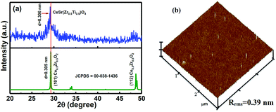
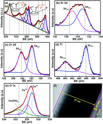
Fig. 1(a) shows the X-ray diffraction (XRD) data of the CSZT membrane. The well-defined plane of (101) at 2θ = 29.15° is found in the XRD pattern, and is indicative of the fluorite-type tetragonal structure. In addition, the (101) peak position of the CSZT membrane was shifted to a lower 2θ value and the d spacing became higher (3.06 Å) relative to those of the Ce0.5Zr0.5O2 reference (JCPDS card no. 00-038-1436). This behaviour is mainly due to the higher ionic radii of the Ti and Sr incorporated into the CSZT membrane. Fig. 1(b) displays the atomic force microscopy (AFM) surface morphology image of the CSZT membrane. The surface roughness was estimated to be 0.39 nm. Fig. 2 displays the XPS spectra of (a) Ce 3d, (b) Sr 3d, (c) Zr 3d, (d) Ti 2p, and (e) O 1s for the CSZT membrane. The Ce 3d, Sr 3d, Zr 3d, Ti 2p, and O 1s element peaks were fitted using a combined symmetric Gaussian–Lorentzian line shape function after a Shirley background subtraction, except for the Ce 3d peak (linear background). Fig. 2(a) demonstrates that the Ce 3d spectra can be deconvoluted into eight peaks: v (882.6 eV), v′ (884.9 eV), v′′ (888.7 eV), v′′′ (898.1 eV), μ (900.4 eV), μ′ (902.7 eV), μ′′ (907.2 eV), and μ′′′ (916.5 eV). The four bands of μ and those of v represent Ce 3d3/2 and 3d5/2, respectively. The peaks of v and μ, v′′ and μ′′, and v′′′ and μ′′′ can be assigned to the (3d94f2)O(2p4), (3d94f1)O(2p5), and (3d94f0)O(2p6) states of Ce4+, respectively, whereas the (3d94f1)O(2p6) state of Ce3+ can be allotted to v′ and μ′.18 The ratio of Ce3+ to total Ce (namely, Ce3+ + Ce4+) is 21.36% higher than in previous studies [19.5% for Ce2(Zr53Ti47)O4 (CZT) film without Sr component].17 This is ascribed to the Sr incorporated into the CSZT membrane enhancing the change from Ce4+ to Ce3+ in the Ce oxidation state. Fig. 2(b) depicts that the Sr 3d3/2 and 3d5/2 double peaks at 134.8 eV and 133.1 eV, respectively, for the CSZT membrane are shifted toward higher binding energies compared with those of the SrTiO3 reference.19 The higher Sr 3d double binding energies of the CSZT film may be attributed to a mixture of Sr2+ ions in the CeO2 lattice. In addition, the ionic radius of Ce4+ (0.99 Å) is larger than that of Ti4+ (0.74 Å).20 Moreover, there is a shift in the Zr 3d3/2 and 3d5/2 split peaks (184.1 and 181.8 eV, respectively) to binding energies that are lower relative to those of ZrO2 film (185.8 and 182.2 eV, respectively),21 as shown in Fig. 2(c). The lower Zr 3d binding energy values for the CSZT film are presumably due to the alloy effect because Ce4+ is the predominant nearest neighboring cation. Fig. 2(d) shows that the Ti 2p1/2 and 2p3/2 split peaks located at 463.6 and 458.1 eV, respectively, are shifted toward binding energies that are lower relative to those of the TiO2 reference (464.3 and 458.7 eV, respectively),22 indicating the formation of Ce–Sr–O–Zr–Ti bonds. Fig. 2(e) demonstrates that the O 1s spectra of the CSZT membrane were convoluted with three appropriate curve-fitting lines. For the three spectra, the first peak at 531.4 eV represents Ce(OH)x, the second peak at 530 eV indicates the Ce3+ state, and the third peak at 529.1 eV indicates the Ce4+ state.23,24 The intensity of the O 1s peak corresponding to the Ce2O3 component is lower than that of CeO2, but is higher relative to our previous reports (the CZT film).17 Fig. 2(f) shows the HR-TEM image of the CSZT membrane. The oxide thickness of the CSZT membrane was evaluated to be ∼47 nm. | ||
| Fig. 1 (a) XRD pattern and (b) AFM image of the CSZT membrane annealed at 800 °C for 30 min in an O2 atmosphere. | ||
 | ||
| Fig. 2 XPS spectra of (a) Ce 3d, (b) Sr 3d, (c) Zr 3d, (d) Ti 2p, and (e) O 1s of the CSZT membrane, and (f) HR-TEM image of the CSZT film. | ||
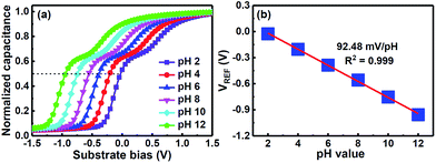
Fig. 3(a) shows the C–V plots of the CSZT EIS sensor annealed at 800 °C for standard buffer solutions. To measure the sensitivity of the EIS device the shift in reference voltage (VREF), as shown in the C–V plots, was measured as it changes with the pH of the buffer solution due to mainly protonation or deprotonation which modifies the surface potential through dipole formation on the sensing membrane. Fig. 3(b) presents the VREF of the CSZT EIS sensor as a function of pH. The CSZT EIS sensor exhibited a super-Nernstian pH sensitivity of 92.48 mV pH−1 with a linear response in the range of pH 2–12, which is far larger than the theoretical Nernstian value (59.4 mV pH−1 at 25 °C). This super-Nernstian response may be attributed to the incorporation of Sr into the CSZT film, which enhances the change in the Ce oxidation state from Ce4+ to Ce3+. In this case, we could suspect that in a mild solution, the oxidized Ce4+ ion and reduced Ce3+ ion participate in the redox reactions below:
| Ce(OH)3 ↔ Ce(OH)2O− + H+ | (1) |
| Ce2O(OH)6 ↔ Ce2O(OH)2O44− + 4H+ | (2) |
| 2Ce(OH)3 + H2O ↔ Ce2O(OH)6 + 2H+ + 2e− | (3) |
 | ||
| Fig. 3 (a) Response of C–V curves and (b) reference voltage plotted with respect to pH at room temperature after inserting the CSZT-EIS sensor into the electrolyte with pH value ranging from 2 to 12. | ||
Substituting eqn (1) and (2) into (3), we can obtain the stoichiometric redox reaction:
| 2Ce(OH)2O− + H2O ↔ Ce2O(OH)2O44− + 4H+ + 2e− | (4) |
From this reaction, only two electrons are transferred per four protons (proton/electron ratio of 2), hence a sensitivity of 118.8 mV pH−1 was achieved because of the mixing of the oxidized CeO2 and reduced Ce2O3 states in the CSZT membrane. The empirical result of the pH sensitivity being over 59.4 mV pH−1 can be explained by there being less than one electron per proton transferred in the redox reaction. In contrast, the pH sensitivity being below 59.4 mV pH−1 might be due to there being more than one electron per proton transferred in this reaction.
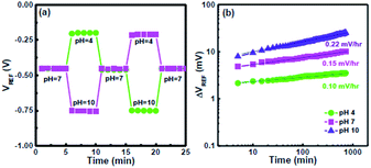
To evaluate the hysteresis of the CSZT EIS sensor, it was subjected to two pH loops of 7 → 4 → 7 → 10 → 7 and 7 → 10 → 7 → 4 → 7 over a period of 1500 s, as shown in Fig. 4(a). The hysteresis voltages were estimated to be 1 and 1.5 mV for the 7 → 4 → 7 → 10 → 7 and 7 → 10 → 7 → 4 → 7 loops, respectively. The smaller hysteresis of the CSZT film is attributed to the formation of a CSZT stoichiometric structure, thus leading to minimal buried oxide. Fig. 4(b) demonstrates the drift rate of an EIS sensor measured at pH 4, 7 and 10 for 12 h. The CSZT EIS sensor exhibited a low drift rate of 0.15 mV h−1 at pH 7. In this study, our CSZT membrane demonstrated a pH detection sensitivity (92.48 mV pH−1) that is superior to those of materials commonly used for EIS or ISFET-based sensors, such as Al2O3 (58 mV pH−1),8 TiO2 (55 mV pH−1),5 Ta2O5 (56–58 mV pH−1),8 ZrO2 (∼55 mV pH−1),9 HfO2 (∼55 mV pH−1),9 Y2O3 (54.5 mV pH−1),11 and CZT (64.42 mV pH−1).17
 | ||
| Fig. 4 (a) Hysteresis curves of the CSZT EIS sensor measured in the pH loops 7 → 4 → 7 → 10 → 7 and 7 → 10 → 7 → 4 → 7. (b) Drift characteristics of the CSZT EIS sensor tested at pH 4, 7 and 10. | ||
Conclusions
In summary, we have demonstrated a high-performance CSZT membrane deposited on a Si substrate through a simple sol–gel spin-coating process. A high pH sensitivity of 92.48 mV pH−1, a small hysteresis voltage of 1 mV, and a low drift rate of 0.15 mV h−1 were achieved by the CSZT EIS sensor. These results are attributed to the incorporation of Sr in the CSZT, which enhances the change in the Ce oxidation state from Ce4+ to Ce3+, resulting in a rise in the ratio of protons to electrons transferred in the redox reaction. This CSZT membrane EIS sensor can be used in future solid-state biosensor devices.Conflicts of interest
There no conflicts to declare.Acknowledgements
The authors would like to thank the Ministry of Science and Technology of Taiwan for financially supporting this research under the contract MOST-106-2221-E-182-063.References
- J. Janata, Principles of Chemical Sensors, Plenum Press, New York, 1990 Search PubMed.
- Glass Electrodes for Hydrogen and Other Cations, ed. G. Eisenman, Marcel Dekker, New York, 1967 Search PubMed.
- P. Bergveld, IEEE Trans. Biomed. Eng., 1970, 17, 70 CrossRef PubMed.
- M. J. Schoning and A. Poghossian, Electroanalysis, 2006, 18, 1893 CrossRef.
- A. Fog and R. P. Buck, Sens. Actuators, 1984, 5, 137 CrossRef.
- T. Yoshinobu, M. J. Schoning, R. Otto, K. Furuichi, Y. Mourzina, Y. Ermolenko and H. Iwasaki, Sens. Actuators, B, 2003, 95, 352 CrossRef.
- M. C. Tanese, D. Fine, A. Dodabalapur and L. Torsi, Biosens. Bioelectron., 2005, 21, 782 CrossRef PubMed.
- T. Matsuo, M. Esashi and H. Abe, IEEE Trans. Electron Devices, 1979, 26, 1856 CrossRef.
- V. Jankovic and J. P. Chang, J. Electrochem. Soc., 2011, 158, P115 CrossRef.
- M. J. Schoning, D. Brinkmann, D. Rolka, C. Demuth and A. Poghossian, Sens. Actuators, B, 2005, 111–112, 423 CrossRef.
- T. M. Pan and K. M. Liao, Sens. Actuators, B, 2007, 128, 245 CrossRef.
- M. Houssa, High-k Gate Dielectrics, Institute of Physics Publishing, Bristol and Philadelphia, 2004 Search PubMed.
- M. Fanciulli and G. Scarel, Rare Earth Oxide Thin Film: Growth, Characterization, and Applications, Springer, Berlin, 2007 Search PubMed.
- M. Ismail, A. M. Rana, I. Talib, T. L. Tsai, U. Chand, E. Ahmed, M. Younus Nadeem, A. Aziz, N. A. Shah and M. Hussain, Solid State Commun., 2015, 202, 28 CrossRef.
- T. M. Pan and W. S. Huang, J. Electrochem. Soc., 2009, 156, G6 CrossRef.
- S. Jeon and H. Hwang, J. Appl. Phys., 2003, 93, 6393 CrossRef.
- S. P. Bag, B. S. Lou, J. L. Her, S. T. Pang and T. M. Pan, IEEE Trans. Electron Devices, 2017, 64, 3975 CrossRef.
- A. Dauscher, L. Hilaire, F. Le Normand, W. Miiller, G. Maire and A. Vasqwz, Surf. Inter. Ana., 1990, 16, 341 CrossRef.
- L. Zhang, W. Tian, Y. Chen, J. Chen, H. Teng, J. Zhou, J. Shi and Y. Sun, RSC Adv., 2016, 6, 83471 RSC.
- A. Gupta, A. Kumar, U. V. Waghmare and M. S. Hegde, Chem. Mater., 2009, 21, 4880 CrossRef.
- N. Takahashi, N. Yoshii, S. Nonobe, T. Nakamura and M. Yoshioka, J. Electron. Mater., 2003, 32, 1107 CrossRef.
- B. S. Kang, Y. T. Sul, S. J. Oh, H. J. Lee and T. Albrektsson, Acta Biomater., 2009, 5, 2222 CrossRef PubMed.
- A. K. Sinha and K. Suzuki, J. Phys. Chem. B, 2005, 109, 1708 CrossRef PubMed.
- V. Stetsovych, F. Pagliuca, F. Dvorak, T. Duchon, M. Vorokhta, M. Aulicka, J. Lachnitt, S. Schernich, I. Matolínova, K. Veltruska, T. Skala, D. Mazur, J. Myslivecek, J. Libuda and V. Matolin, J. Phys. Chem. Lett., 2013, 4, 866 CrossRef PubMed.
| This journal is © The Royal Society of Chemistry 2018 |
