DOI:
10.1039/C8RA03554G
(Paper)
RSC Adv., 2018,
8, 25423-25435
Novel ionic polymer–metal composite actuator based on sulfonated poly(1,4-phenylene ether-ether-sulfone) and polyvinylidene fluoride/sulfonated graphene oxide †
Received
25th April 2018
, Accepted 30th June 2018
First published on 16th July 2018
Abstract
In the present work, sulfonated graphene oxide and sulfonated poly(1,4-phenylene ether-ether-sulfone) were blended with polyvinylidene fluoride to create a novel ionic polymer–metal composite actuator with enhanced performance. An ionic polymer–metal composite membrane in the protonated form was prepared by casting a composite blend of sulfonated poly(1,4-phenylene ether-ether-sulfone), polyvinylidene fluoride and sulfonated graphene oxide onto a plating of platinum metal as the electrode. The degree of sulfonation of poly(1,4-phenylene ether-ether-sulfone) was characterized using ion-exchange capacity measurements. Energy dispersive X-ray and transmittance electron microscopy analyses were carried out to analyze the chemical composition and detailed structure. Deposition of the platinum electrode and the surface morphology of the proposed ionic polymer–metal composite actuator were assessed using scanning electron microscopy analysis. The electrical properties were measured using cyclic voltammetry, linear sweep voltammetry and proton conductivity. These measurements confirmed the better actuation performance of the fabricated ionic polymer–metal composite actuator compared to other expensive ionic polymer-based actuators, in terms of its high ion-exchange capacity, good proton conductivity, high current density and large bending deflection. The robust, flexible and mechanically strong membrane actuator, fabricated via the synergistic combination of sulfonated poly(1,4-phenylene ether-ether-sulfone), polyvinylidene fluoride and sulfonated graphene oxide, has considerable potential as an actuator material for robotic, bio-mimetic and other applications.
1. Introduction
A great amount of effort has been dedicated to the development of efficient materials that mimic the performance of biomimetic actuators under electrical stimuli. Within this field, electro-active polymers (EAPs) have been found to be a promising candidate and an attractive emerging technology with applications in biomedical devices, artificial muscles and bioinspired locomotive robots, etc.1–3 Ionic polymer–metal composites (IPMCs) are an ideal type of EAP, because of their advantageous properties, such as low driving voltages, large bending deformation, biomimetic actuation and high energy density.4,5 A number of applications have been suggested for IPMC actuators, including artificial muscles, robotic actuators and dynamic sensors.6–14 In general, IPMC actuators typically consist of a thin membrane of ion-exchange polymeric material coated with a noble metal (platinum, gold, etc.) electrode surface. Perfluorosulfonate polymers such as Nafion have been widely studied in IPMC actuators, because of the thermal and chemical stability of the perfluorinated polymeric structure.15–19 The fixed ionic groups in the perfluorinated polymer chains can absorb water molecules and form ionic bonds with metallic cations such as Na+ or Li+ after an ion-exchange process. These weakly-bonded hydrated cations can move through the ionic nanochannels in the polymer membranes under an applied electric potential, resulting in the bending of the IPMC membrane. Although they have many advantages, the IPMC actuators developed to date often suffer from problems such as short cycle lifetimes, poor mechanical properties of the polymer, slow response and high cost.
In this article, a cost-effective IPMC membrane based on sulfonated poly(1,4-phenylene ether-ether-sulfone) (SPEES), polyvinylidene fluoride (PVDF) and sulfonated graphene oxide (SGO), combined with a platinum (Pt) electrode plated using an electroless plating method, is reported. The proposed IPMC membrane has high durability, a fast response time and a low operating voltage. Poly(1,4-phenylene ether-ether-sulfone) (PEES) is quite a new material to be used in the field of membrane technology. It contains aromatic and ether linkages, which provide the necessary strength, molecular rigidity and good processability.20 However, the hydrophobic nature of PEES restricts its wide-scale utilization in the field of actuators and sensors. Hence, PEES was chemically modified using a sulfonation reaction to increase the much-required hydrophilicity, which is an important parameter for IPMC membranes.21 PVDF, which exhibits good flexibility, chemical stability and plasticity, is a commercial piezoelectric material. It can convert mechanical energy into electrical energy, allowing the actuators to be used for generating electricity. Because of its piezoelectric behavior, PVDF has been used in vibration control,22,23 sensing,24–26 energy harvesting27,28 and many other applications.29–32 The high ion-exchange capacity (IEC) and large water holding capacity (WH) of pristine SPEES cause partial dissolution of the SPEES membrane after immersion in water. Therefore, to enhance the mechanical strength, electrical properties and stability in water, it was necessary to make a composite blend of SPEES, PVDF and SGO in an appropriate ratio for the fabrication of a novel SPEES/PVDF/SGO/Pt-based IPMC membrane.
Recently, graphene has been attracting increasing attention,33 mainly due to its thermal conductivity, great mechanical stiffness, high electrical conductivity and large specific surface area.34–37 Herein, SGO was synthesized and it was blended with SPEES/PVDF polymer solution. SGO is an important functionalized graphene material that features rich oxygen groups on its surface. It has attracted increasing attention as a filler in chemically-functionalized materials, for enhancing interfacial interactions.6 The addition of SGO increases the IEC and WH of the composite polymer membrane, resulting in a large and fast tip displacement of the IPMC actuator. The composite material possesses a desirable combination of properties, which is not possible in the individual components. The combination of SPEES and SGO increases the amount of sulfonic acid groups in the IPMC membrane, which leads to a greater degree of Na+ exchange through ion-exchange processes and enhances the IEC and proton conductivity (PC), resulting in better actuation performance. Here, SPEES/PVDF works as a base material to form an intermediate layer for ion migration and expands or contracts relative to SGO under an electrical stimulus. The collective properties of the individual materials in the developed IPMC membranes create a large degree of bending deformation, resembling that of natural muscles. The developed SPEES/PVDF/SGO/Pt-based IPMC membrane exhibits high current density, IEC, mechanical strength and PC, and is inherently capable of exhibiting enhanced bending performance over a longer lifetime.
2. Experimental
2.1 Materials
Poly(vinylidene fluoride) beads, poly(1,4-phenylene ether-ether-sulfone) pellets (Tg 192 °C) and N,N-dimethylacetamide ≥ 99% (NMA) were obtained from Sigma-Aldrich, USA. Tetra-amineplatinum(II)chloride monohydrate (Pt(NH3)4Cl2·H2O, crystalline) was purchased from Alfa Aesar, USA. Ammonium hydroxide (NH4OH) (25%), hydrochloric acid (HCl) (67%), sulfuric acid (H2SO4), potassium permanganate (KMnO4), hydrogen peroxide (H2O2) and sodium nitrate were obtained from Merck Specialties Pvt. Ltd., India, while sodium borohydride (NaBH4) was purchased from Loba Pvt. Ltd., India. All chemicals were used as received without further purification.
2.2 Reagents and solutions
Aqueous solutions of HCl (2 M), NaNO3 (1 M), tetra amineplatinum(II)chloride monohydrate (0.04 M), NH4OH (5.0%) and NaBH4 (5.0%) were prepared using demineralized water (DMW).
2.3 Synthesis of sulfonated graphene oxide
Graphene oxide (GO) was synthesized from graphite flakes using a modified Hummers' method.38,39 For this, 2.0 g of graphite was added to 46 mL of concentrated sulfuric acid in an ice bath. After 30 min of mechanical agitation, sodium nitrate (1.5 g) was added and the mixture was cooled to 0 °C. KMnO4 (6 g) was added very slowly to the mixture with vigorous agitation to keep the temperature below 20 °C. The reaction mixture was constantly stirred for up to 10 h at 35 ± 5 °C to form a thick paste. Then DMW was added to the reaction system followed by stirring for 1 h at 60 ± 5 °C. An additional 150 mL of DMW was added, followed by the slow addition of 15 mL of H2O2 (3%), which turned the color of the mixture from dark brown to golden yellow. To remove metal ions, the filtered reaction mixture was washed with 0.1 M HCl aqueous solution, followed by washing with DMW until it became neutral. The resulting solid was filtered and dried under vacuum at 65 °C. Finally, 0.1 g of GO powder was dispersed in 100 mL DMW under strong mechanical agitation followed by sonication for 1 h. Reduction was carried out by adding 0.2 g of NaBH4 to the dispersion with vigorous stirring for 30 min, followed by heating at 120 °C for 3 h. During the reduction process, the yellow-brown solution was gradually converted into a black precipitate. The resulting black solid sulfonated GO was isolated by centrifugation and after washing with DMW, it was dried in a thermostated oven at 60 °C for further use.
2.4 Sulfonation of PEES
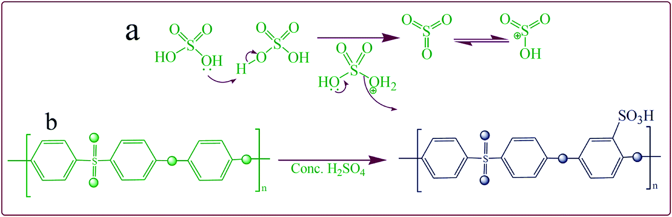
Sulfonation of base polymer PEES was carried out using a slightly modified method as reported by Unveren et al.40,41 PEES (5 g) was dissolved completely in an excess of concentrated H2SO4 (125 mL) by strong mechanical agitation (450 rpm) for a time period of 36 h. Here, concentrated H2SO4 was used as a solvent as well as a sulfonating agent. After constant stirring for the required reaction time to obtain white sulfonated PEES (SPEES) strings (Fig. 1), the polymer solution was gradually precipitated in ice-cold DMW. The decanted sulfonated PEES strings were repeatedly washed with DMW until the pH of the washing water was approximately 6–7. The sulfonated PEES was hydrophilic in nature, and showed considerable swelling during the neutralization process. The swollen sulfonated PEES strings were dried in a thermostated oven for 24 h at 60 °C and then at room temperature (25 ± 3).
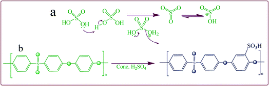 |
| | Fig. 1 Plausible mechanism of (a) electrophile generation and (b) its subsequent attack on PEES. | |
2.5 Preparation of composite polymer membrane
The ionic polymer membrane was fabricated by first dissolving 20 wt% dried SPEES and 15 wt% PVDF in N,N-dimethylacetamide (NMA) separately. After complete dissolution, the SPEES and PVDF solution was blended by strong mechanical agitation at room temperature for 12 h. A homogeneous blend was prepared by adding an appropriate amount of SGO dispersion to the SPEES/PVDF solution under constant stirring for 24 h. Upon ensuring complete dissolution, the solution was degassed by sonication for 30 min before casting. Finally, the homogeneous solution was placed into Petri dish and kept in a thermostated oven at 80 °C for drying. The dried membrane was washed several times with acetone and DMW to remove residual solvent.
2.6 Characterization
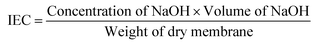
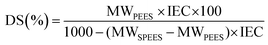
The SPEES/PVDF/SGO composite polymer membrane surface was coated with Pt metal ions to create the electrode via chemical reduction or an electroless plating method as reported by Inamuddin et al.7 The IEC and degree of sulfonation (DS) were investigated using a simple titration method as mentioned in the literature.11,42 The IEC and DS of pristine SPEES, SPEES/PVDF and SPEES/PVDF/SGO composite polymer membranes were determined using the following equations:| |
 | (1) |
| |
 | (2) |
where, MWPEES and MWSPEES are the molecular weights of single monomer units of the polymers PEES (324) and SPEES (PEES-SO3Na (426)), respectively.
The WH and PC were measured using the method reported by Inamuddin et al.8,43,44 Scanning electron micrographs (SEM) were obtained on a scanning electron microscope (SEM Jeol, JSM-6510LV, Japan). The elemental composition was investigated using an energy dispersive X-ray (EDX) spectrometer (Oxford instruments INCA X-Act, S. No. 56756, UK), while transmission electron microscopy (TEM) (TEM Jeol, JEM-2100, Japan) was used to observe the detailed structure of the fabricated IPMC membranes. UV-visible absorption spectroscopy was performed using a PerkinElmer spectrophotometer, Lambda 25. Young's moduli and ultimate tensile strengths of the fabricated IPMC membranes were determined using a universal testing machine (Model: H50 KS, Shimadzu Corp.), with a 25 mm gauge length under a testing speed of 5 mm min−1. Cyclic voltammetry (CV) at ± 3 V and linear sweep voltammetry (LSV) at 0–3 V with a step of 100 mV s−1 were performed using an Autolab 302N modular potentiostat/galvanostat. The SPEES/PVDF/SGO/Pt IPMC membranes were immersed in an aqueous solution of 0.2 M NaOH at room temperature for 6 h to exchange metal cations (Na+) through an ion-exchange process. The successive steps of the bending response at 0–5 V DC were analyzed with a laser displacement sensor (Model: OADM 20S4460/S14F; Baumer Electric, Germany). To assess the repeatability and enhanced performance of the fabricated IPMC membranes, multiple experiments were conducted to investigate the deflection hysteresis behavior. Several trials were also conducted for load characterization followed by calculating the normal distribution function.
3. Results and discussion
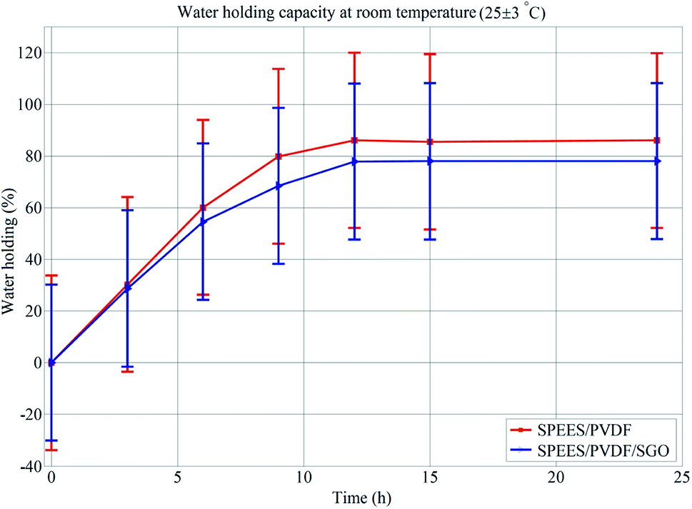
The ionic conductivity of PEES was obtained by introducing sulfonic acid groups (–SO3H) to the aromatic backbone of hydrophobic PEES through a sulfonation reaction. An electrophile is generated (Fig. 1a) and an electrophilic substitution reaction takes place at the aromatic ring between the ether bridges as shown in Fig. 1b. The electron-attracting nature of the neighboring sulfonyl group lowers the electron density of other two aromatic rings in the repeating units. The electron-rich benzene ring then reacts with the electrophile to give the sulfonated product. The degree of sulfonation of SPEES was determined to be 126% (ESI Table 1†), which is adequately high and allows for excessive swelling, enabling sufficiently high proton conduction. It was observed that the high degree of sulfonation of pure SPEES causes partial dissolution of the polymer due to excessive swelling in water. The blending of PVDF and SGO with SPEES leads to the enhanced mechanical strength, surface area for chemical reactions, IEC, PC, electrical properties and thermo-mechanical stability of the prepared SPEES/PVDF/SGO composite membrane actuator. These enhancements are essential for the increased performance of the IPMC actuator for robotic applications. To assess the solvent holding capacity and stability, the fabricated membranes were immersed in DMW at room temperature and 80 °C for 24 h. It was observed that the membranes were fully stable in DMW without any distortion. After 24 h of immersion, the maximum WH values for the SPEES/PVDF and SPEES/PVDF/SGO membranes were found to be 86 and 78% with standard deviations (SDs) of 0.63 and 0.64% at room temperature and 80 °C, respectively (ESI Table 1†). To check the repeatability of WH of the fabricated polymer composite membranes, the same experiment was repeated five times. The average of five experimental values was taken to plot the error bars of WH, as shown in Fig. 2. The WH repeatability experiment suggests that there was no significant change in the WH values of the SPEES/PVDF and SPEES/PVDF/SGO membranes after repetition of the same experiment. This, in turn, confirms the better performance of the fabricated membrane actuators in aqueous media. The high WH value of the polymer composite membrane improves the dielectric constant and PC of the IPMC membranes.45,46 However, a high solvent holding capacity leads to reduced mechanical stability; therefore, an elevated WH is vital for the movement of hydrated cations and water molecules under an applied electrical potential. The addition of PVDF and SGO decreases the porosity and number of acidic sites. Hence, the excessive swelling nature of SPEES was minimized due to a decrease in the WH coupled with an increase in the mechanical stability. Notably, the WH of the SPEES/PVDF/SGO/Pt-based IPMC membrane was much higher than those of Nafion-based IPMCs, suggesting the more flexible nature and improved actuation performance of the fabricated IPMC membrane.
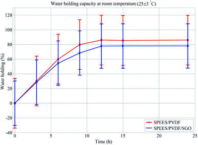 |
| | Fig. 2 Error bars of WH for SPEES/PVDF and SPEES/PVDF/SGO composite membranes. | |
The high IEC values of the ion-exchange polymer membranes mean that a larger amount of hydrated cations moves toward the negative electrode by the action of the applied potential. Electro-osmosis and electrophoresis cause greater volume expansion towards cathode side, resulting in a larger bending deflection.47,48 Furthermore, the high IEC value also leads to the deep insertion of the Pt particles within the porous surface of the polymer membranes via a chemical reduction plating method, which enhances the electric current density and capacitance by reducing the resistance of the IPMC actuator.15,30,49 The IEC values of the SPEES, SPEES/PVDF/Pt and SPEES/PVDF/SGO/Pt membranes were found to be 2.8, 1.5 and 1.95 meq. g−1, respectively, with a standard deviation of 0.007 meq. g−1 for the dry membranes (ESI Table 1†). The fabricated composite polymer membrane actuator shows a higher IEC than other conventional polymer-based actuators.7 The high IEC value may be due to the greater number of sulfonic acid groups present in SPEES and SGO of the SPEES/PVDF/SGO/Pt IPMC membrane actuator. The IEC analysis (ESI Table 1†) of the fabricated SPEES/PVDF/SGO/Pt membrane confirms that the proposed actuator has a high solvent holding capacity, IEC and ionic content compared to Nafion-based IPMC actuators,7 which confirms the enhanced and reliable performance of the fabricated IPMC actuator. The maximum PC values of the SPEES/PVDF/Pt and SPEES/PVDF/SGO/Pt IPMC membranes were found to be 1.04 × 10⁻² and 1.62 × 10⁻² S cm−1, respectively. The high PC of the SPEES/PVDF/SGO/Pt membrane may due to the addition of functionalized SGO. The higher value of PC causes the fast transport of more hydrated cations towards the cathode, to create a pressure imbalance inside the membrane. This enables the enhanced performance of the fabricated membrane actuator. Furthermore, the electric current of an IPMC actuator also increases with an increase in PC. It has been reported that a high electric current increases the actuation of IPMCs under applied AC and DC voltages.15,50,51 Thus, the results of WH, IEC and PC reveal that the SPEES/PVDF/SGO/Pt-based IPMC membrane actuator is capable of showing larger displacement and faster actuation than the SPEES/PVDF/Pt-based IPMC.
3.1 UV-visible spectroscopy
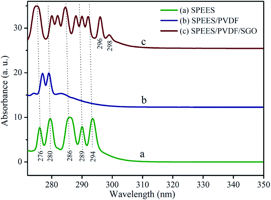
UV-visible (UV-Vis) spectra reveal the intimate interaction between the composite polymer blends of SPEES, PVDF and SGO. Fig. 3 represents the UV-Vis absorption spectra of the pure SPEES, SPEES-PVDF and SPEES/PVDF/SGO membranes. The absorbance spectrum of the pure SPEES polymer membrane shows characteristic absorption peaks in the UV range of ∼275–300 nm (Fig. 3a). In Fig. 3b, the absorbance pattern of the SPEES/PVDF polymer membrane shows a slight shifting of the peak at 275 nm towards the bathochromic region, along with the disappearance of other peaks present in the pattern for pure SPEES (Fig. 3a). These results suggest a chemical interaction between SPEES and PVDF. The absorbance spectrum of the SGO-loaded SPEES/PVDF ionic polymer membrane shows additional absorption peaks at 282, 288, 296 and 298 nm (Fig. 3c), along with the reappearance of peaks (as shown in Fig. 3a), due to the synergetic effects of SGO and the SPEES/PVDF blend. In comparison to the positions of the characteristic absorbance peaks of pure SPEES (Fig. 3a), slight red-shifting in the absorbance peaks at 280, 289 and 294 nm in the SGO-loaded SPEES/PVDF ionic polymer membrane was observed (Fig. 3c). The results obtained from the analysis of the UV-Vis absorbance patterns give evidence for chemical interactions between SPEES, PVDF and SGO in the composite blend (SPEES/PVDF/SGO) used for the fabrication of the IPMC actuator.
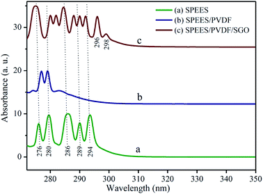 |
| | Fig. 3 UV-visible spectra of (a) pure SPEES, (b) SPEES/PVDF and (c) SPEES/PVDF/SGO polymer membranes. | |
3.2 SEM-EDX and TEM studies
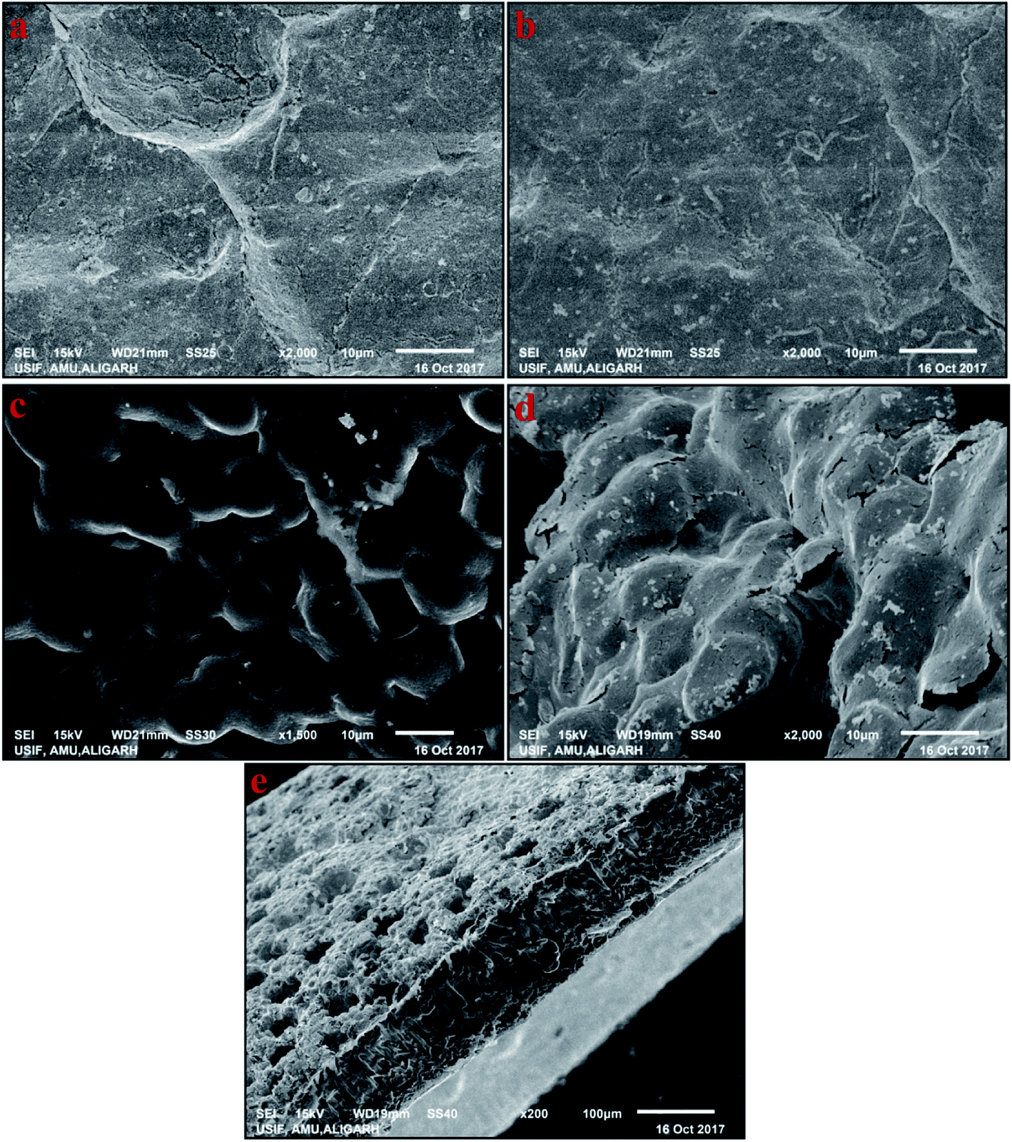
The magnitude of the deflection of ionic polymer-based actuators depend on the nature of the interface between the electrode and the polymer membrane, as well as on the structure of the electrodes.16 Hence, SEM analysis was used to investigate the surface and cross-sectional morphologies of the SPEES/PVDF/SGO membrane without an electrode and the SPEES/PVDF/SGO/Pt membrane with Pt as an electrode (Fig. 4a–e). Fig. 4a and b show the surface of the SPEES/PVDF/SGO composite membrane without an electrode. The composite membrane has an unvarying surface, which suggests the homogenous blending of SPEES, PVDF and SGO. As shown in Fig. 4c and d, the Pt particles that comprise the electrode are densely deposited on the surface of the SPEES/PVDF/SGO membrane. A uniform flower-like deposition of the Pt layer on the surface of the composite polymer membrane can be clearly seen. The functional groups on SPEES and SGO are likely to offer interfacial contact between the composite polymer blend and the Pt electrode layer. Some microcracks can be clearly seen on the SPEES/PVDF/SGO/Pt IPMC membrane surface, resulting from the sample drying before SEM analysis. As illustrated in Fig. 4e, the developed SPEES/PVDF/SGO/Pt ionic polymer composite membrane exhibits a highly porous structure because of the hydrophilic nature of SPEES and blending with SGO. The extremely porous structure of the SPEES/PVDF/SGO ionic polymer leads to enhanced electrochemical properties and high IEC, PC and WH. The cross-sectional micrograph also shows that the Pt electrodes are deposited on both surfaces of the SPEES/PVDF/SGO ionic polymer membrane (Fig. 4e).
 |
| | Fig. 4 SEM images of membranes based on (a and b) SPEES/PVDF/SGO, and (c and d) SPEES/PVDF/SGO/Pt and (e) cross-sectional view of SPEES/PVDF/SGO/Pt. | |
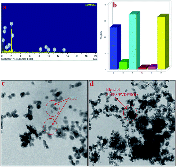
The EDX results of the developed IPMC membrane are shown in Fig. 5a and b. The EDX spectrum of the SPEES/PVDF/SGO/Pt IPMC membrane surface shows the characteristic peaks of several elements (Fig. 5a), while the percentages of carbon (C), oxygen (O), sulfur (S), fluorine (F), sodium (Na) and platinum (Pt) on the surface of the SPEES/PVDF/SGO/Pt-based IPMC actuator are shown in Fig. 5b. The characteristic peaks of sulfur (S) confirm the sulfonation and functionalization of PEES and GO (Fig. 5a). The higher percentage of Pt confirms the excellent and uniform coating of the metal electrode on the surface of the SPEES/PVDF/SGO/Pt-based IPMC membrane actuator.
 |
| | Fig. 5 EDX spectra (a and b) and TEM images (c and d) of the fabricated SPEES/PVDF/SGO/Pt IPMC membrane actuator. | |
Fig. 5c and d show the TEM micrographs used to characterize the SPEES/PVDF/SGO ionic polymer membrane. Typical SGO, which is homogeneously distributed, can be clearly seen in Fig. 5c. After blending SGO with SPEES and PVDF ion-exchange polymers, the SGO layers stack together to form a composite structure, as shown in Fig. 5d. It can be clearly seen that SGO is homogeneously blended and covers the grey background of the SPEES and PVDF matrix of the SPEES/PVDF/SGO composite polymer membrane (Fig. 5d). The TEM analysis reveals the uniform composite blending of SPEES, PVDF and SGO in the fabricated IPMC actuator.
3.3 Tensile strength
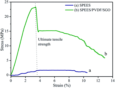
Young's modulus and ultimate tensile strength were the parameters used to assess the fundamental mechanical properties of the fabricated IPMC membranes, which play a significant role in the actuation performance of the actuator. To determine the mechanical stability, fabricated membranes of 20 mm wide and 0.12 mm thick were fixed into a universal testing machine with a fixed gauge length of 25 mm. Fig. 6a and b show the stress–strain curves of the SPEES and SPEES/PVDF/SGO/Pt composite membranes and their mechanical properties are shown in Table 1.
 |
| | Fig. 6 Stress–strain curves of pure SPEES and SPEES/PVDF/SGO ionic polymer membranes. | |
Table 1 Mechanical properties of SPEES and SPEES/PVDF/SGO ionic polymer membranes
| Membranes |
Young's modulus (MPa) |
Ultimate tensile strength (MPa) |
Elongation at break (%) |
| SPEES/PVDF/SGO |
798.45 ± 8.37 |
23.14 ± 1.97 |
12.90 ± 0.86 |
| SPEES |
37.29 ± 6.67 |
1.58 ± 0.22 |
10.50 ± 0.91 |
The stress strain curve was used to calculate Young's modulus and the ultimate tensile strength of the SPEES and SPEES/PVDF/SGO membranes. Young's modulus and the ultimate tensile strength of the pure SPEES membrane were 37.29 and 1.58 MPa, with SDs of 6.67 and 0.22 MPa, respectively (Table 1). Meanwhile, Young's modulus and the ultimate tensile strength of the SPEES/PVDF/SGO composite polymer membrane were found to be 798.45 and 23.14 MPa, with SDs of 8.37 and 1.97 MPa, respectively (Table 1). The results obtained from the tensile properties demonstrate that the composite blend of the SPEES/PVDF/SGO membrane provides high molecular rigidity and mechanical strength, leading to higher tensile moduli relative to the SPEES membrane (Fig. 6a). The improved mechanical properties of the SPEES/SPVDF/SGO composite polymer membranes are due to PVDF and SGO having excellent mechanical strength as well as superior electrical properties, making them great alternatives for the production of IPMC actuators with enhanced performance.
3.4 Thermogravimetric analysis (TGA)
The thermal stability behavior of the SPEES/PVDF and SPEES/PVDF/SGO polymer composite membranes were investigated using thermogravimetric analysis (TGA). TGA thermograms of the SPEES/PVDF and SPEES/PVDF/SGO composite polymer membranes show that both ionomeric polymer membranes exhibit similar three-step weight loss patterns (Fig. 7a and b). The initial weight loss at the temperature of 50–200 °C in the SPEES/PVDF and SPEES/PVDF/SGO membranes occurs due to the removal of water molecules absorbed or bonded to the sulfonic groups. The second weight loss starting from about 300 °C and up to 500 °C is related to the decomposition of sulfonic acid groups present in the SPEES polymer. The third decomposition of the composite polymer membranes located at 400–500 °C is associated with the degradation of the PVDF polymer backbone. The last decomposition at around 500–600 °C onwards is assigned to the degradation of the SPEES main chain. The thermal gravimetric study suggests that the SPEES/PVDF/SGO ionic polymer membrane exhibits good thermal stability. This reveals the enhanced performance of the proposed IPMC membrane even at high temperature (Fig. 7).
 |
| | Fig. 7 TGA thermograms of (a) SPEES/PVDF and (b) SPEES/PVDF/SGO ionic polymer membrane actuators. | |
3.5 Electrical properties
Fig. 8 and 9 show the electrochemical properties of the SPEES/PVDF/Pt and SPEES/PVDF/SGO/Pt IPMCs. The current–voltage hysteresis I–V (at ±3 V) and LSV curves (at 0–3 V) under a scan rate of 100 mV s−1 were studied to assess the electrochemical properties of the prepared IPMCs. The LSV curve (Fig. 8) suggests that the SPEES/PVDF/SGO/Pt IPMC has a higher current density than SPEES/PVDF/Pt, which may be due to the presence of SGO. SGO increases the surface area and sulfonic acid groups in the composite polymer membranes, which increases the IEC, PC and uniformity of the Pt electrode layer deposited on the membrane surface. This increases the rate of ionic transfer in the SPEES/PVDF/SGO/Pt membrane, which is required for achieving enhanced performance in the IPMC membranes. Different sequential small peaks and irregular shapes were observed, indicating that ionic diffusion in the prepared IPMC membrane was chaotic, which may be attributed to the rough and porous surface (Fig. 4c and d).52,53 The I–V hysteresis curves of the SPEES/PVDF/Pt and SPEES/PVDF/SGO/Pt membranes appear similar in shape but differ in the magnitude of the current density (Fig. 9). The symmetric shape of the CV curves can be assigned to excellent charge distribution in the whole surface region of the developed IPMC (Fig. 9). The electrical studies reveal that the observed current density of the fabricated cost-effective IPMC membrane was remarkably higher than several other IPMCs reported so far.7,8,10 The improved electrochemical properties in the proposed IPMC may be due to the addition of electrically conductive SGO, which increases the charge transfer due to the increase in the surface area for chemical reactions. The benefit of the higher IEC, PC and uniform Pt electrode was indicated by the capacitor-like shape of the I–E curve of the SPEES/PVDF/SGO/Pt IPMC membrane. The higher current density reflects the energy storage ability of the prepared IPMC membrane, which is responsible for the better actuation performance and large deformation of the polymer membrane under an applied voltage. These results also reveal that the thick Pt electrode layer, with a highly nano-dispersed structure on the SPEES/PVDF/SGO/Pt membrane actuator, may offer a high current density with a large interfacial area due to SGO. This is expected to be advantageous in improving the actuation performance of the fabricated IPMC.
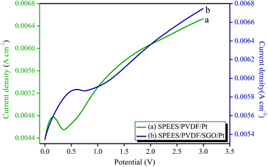 |
| | Fig. 8 LSV curves of the SPEES/PVDF/Pt and SPEES/PVDF/SGO/Pt IPMC membrane actuators. | |
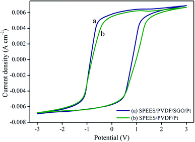 |
| | Fig. 9 Cyclic voltammetry curves of the SPEES/PVDF/Pt and SPEES/PVDF/SGO/Pt IPMC membrane actuators. | |
3.6 Electromechanical properties (bending and force behavior analysis)
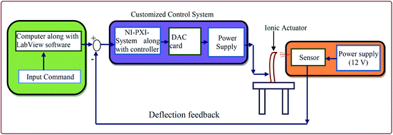
To investigate the mechanical behavior of the fabricated IPMC membrane actuators, they were experimentally tested. A graphical representation of the experimental test setup is shown in Fig. 10. An actual testing setup was developed and the SPEES/PVDF/Pt and SPEES/PVDF/SGO/Pt IPMC membranes were fixed in a holder in a cantilever configuration connected to digital power supply and a NI-PXI System (ESI Fig. 1†). This configuration sent the desired controlled voltage (±5 V) to the IPMC membrane. Moreover, a VI was designed with LabVIEW software for controlling the voltage, where a proportional integral derivative (PID) control system feature enabled the incorporation of the PID parameters. For proper actuation of the fabricated IPMC membranes, an algorithm was also developed. A laser displacement sensor was placed in front of the fabricated IPMC to measure the tip displacement with respect to the applied voltage. This sensor was also used as a displacement feedback for controlling and measuring the tip displacement. Data conversion was performed by converting the data from RS-485 to RS-232 communication protocol, interfaced with the NI-PXI system and NI-VISA interface software module in LabVIEW VI, in order to attain appropriate communication between the sensor and input command. Simultaneously, the DAQ assistant of the NI-PXI system confirmed the actuating voltage from the programmable power supply. The displacement sensor gave information regarding reaching the final displacement point by checking the deflection behavior of IPMC.
 |
| | Fig. 10 Schematic diagram of the testing setup to measure the bending behavior of the SPEES/PVDF/SGO/Pt-based IPMC actuator. | |
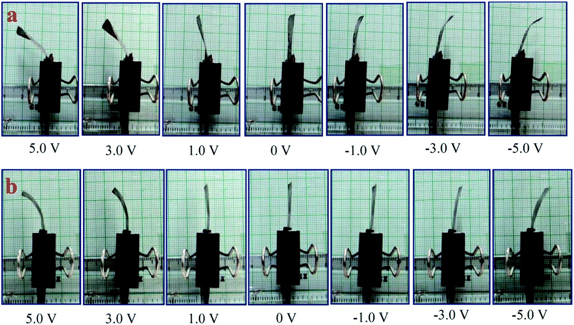
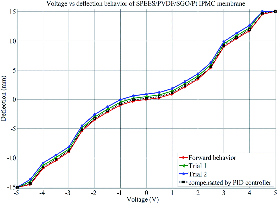
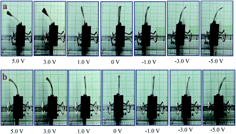
The successive steps of deflection behavior of the SPEES/PVDF/Pt and SPEES/PVDF/SGO/Pt IPMC membranes under applied voltages (0–5 V) were observed, as shown in Fig. 11. Multiple experiments were conducted and deflection data were collected at varying voltages to investigate the hysteresis behavior. The averages of the values of repeated experiments were plotted, as shown in Fig. 12 and 13. To check the repeatability of the SPEES/PVDF/Pt and SPEES/PVDF/SGO/Pt IPMC membranes, the same experiments were conducted for both IPMC membranes 3 × 10 (30) times, as given in the ESI (ESI Tables 2–5†). The deflection values for the first trial for the SPEES/PVDF/Pt and SPEES/PVDF/SGO/Pt IPMC membranes (size = 30 mm length × 10 mm width × 0.12 mm thickness) are provided in Tables 2 and 3, respectively. To plot and observe the deflection hysteresis behavior of the fabricated IPMCs, the average value of each set of 10 experiments was taken as one trial at multiple repeats. From these hysteresis curves (Fig. 12 and 13), it is clear that when the voltage increases, the IPMCs show steady-state behavior, but after reducing the voltage from high (5 V) to low (0 V), the IPMC did not follow the same path and shows some deflection error (hysteresis). This could be minimized through a PID control system, where PID parameters were tuned in LabVIEW software. The hysteresis was reduced by up to 80%. Fig. 12 and 13 clearly show that with the repetition of deflection experiments for SPEES/PVDF/Pt, the deflection error increases and the hysteresis curve becomes broader, which lowers the performance of SPEES/PVDF/Pt in comparison to the SPEES/PVDF/SGO/Pt IPMC membrane. The enhanced performance of the SPEES/PVDF/SGO/Pt IPMC membrane blended with SGO was due to the high current density and charge transfer and large surface area for chemical reactions, which reflects the energy storage ability of the prepared IPMC membrane.
 |
| | Fig. 11 Deflection behavior of (a) SPEES/PVDF/SGO/Pt and (b) SPEES/PVDF/Pt IPMC membranes. | |
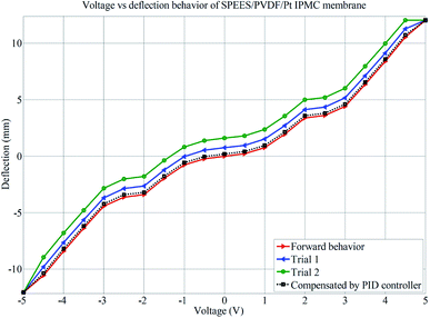 |
| | Fig. 12 Deflection performance of SPEES/PVDF/Pt for hysteresis analysis. | |
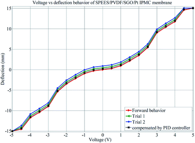 |
| | Fig. 13 Deflection performance of SPEES/PVDF/SGO/Pt for hysteresis analysis. | |
Table 2 Deflection data of SPEES/PVDF/Pt IPMC membrane at different applied voltages
| Deflection (mm) |
Voltage (V) |
| 0 V |
0.5 V |
1.0 V |
1.5 V |
2.0 V |
2.5 V |
3.0 V |
3.5 V |
4.0 V |
4.5 V |
5.0 V |
| d1 |
0 |
0.20 |
0.90 |
1.90 |
2.50 |
3.20 |
4.80 |
6.50 |
8.5 |
10.20 |
12.2 |
| d2 |
0 |
0.20 |
0.80 |
1.80 |
2.60 |
3.60 |
4.20 |
6.40 |
8.90 |
10.50 |
11.90 |
| d3 |
0 |
0.10 |
0.70 |
1.90 |
2.90 |
3.40 |
4.50 |
6.20 |
8.4 |
10.80 |
11.80 |
| d4 |
0 |
0.30 |
0.60 |
2.20 |
3.80 |
3.80 |
4.30 |
6.70 |
8.30 |
10.80 |
12.4 |
| d5 |
0 |
0.20 |
0.80 |
1.90 |
3.40 |
3.40 |
4.90 |
6.20 |
8.40 |
11.50 |
12.50 |
| d6 |
0 |
0.40 |
0.80 |
2.10 |
3.70 |
3.70 |
4.30 |
6.80 |
8.80 |
10.20 |
12.00 |
| d7 |
0 |
0.10 |
0.90 |
2.30 |
3.60 |
3.60 |
4.70 |
6.00 |
8.30 |
10.50 |
12.30 |
| d8 |
0 |
0.20 |
0.60 |
1.90 |
3.80 |
3.80 |
4.10 |
6.30 |
8.00 |
10.20 |
11.80 |
| d9 |
0 |
0.30 |
0.90 |
1.80 |
3.70 |
3.70 |
4.30 |
6.20 |
8.10 |
10.10 |
12.00 |
| d10 |
0 |
0.20 |
0.70 |
1.80 |
3.90 |
3.90 |
4.10 |
6.40 |
8.20 |
10.60 |
11.60 |
| Mean |
12.05 |
| Standard deviation |
0.291 |
Table 3 Deflection data of SPEES/PVDF/SGO/Pt IPMC membrane at different applied voltages
| Deflection (mm) |
Voltage (V) |
| 0 V |
0.5 V |
1.0 V |
1.5 V |
2.0 V |
2.5 V |
3.0 V |
3.5 V |
4.0 V |
4.5 V |
5.0 V |
| d1 |
0 |
0.20 |
1.10 |
2.50 |
3.40 |
5.200 |
8.80 |
10.20 |
11.00 |
14.00 |
14.90 |
| d2 |
0 |
0.20 |
1.00 |
2.60 |
3.60 |
5.400 |
8.70 |
10.10 |
11.50 |
13.20 |
14.80 |
| d3 |
0 |
0.10 |
0.90 |
2.40 |
3.10 |
4.90 |
9.10 |
10.50 |
11.50 |
14.50 |
15.30 |
| d4 |
0 |
0.30 |
0.80 |
2.30 |
3.40 |
5.60 |
9.20 |
10.80 |
12.40 |
14.50 |
15.00 |
| d5 |
0 |
0.50 |
1.20 |
1.90 |
3.60 |
5.70 |
9.30 |
10.00 |
11.80 |
14.80 |
15.10 |
| d6 |
0 |
0.10 |
1.10 |
1.8 |
3.60 |
5.80 |
9.40 |
10.40 |
10.90 |
14.90 |
14.90 |
| d7 |
0 |
0.20 |
0.80 |
2.00 |
3.90 |
5.80 |
9.70 |
10.30 |
12.10 |
14.50 |
14.80 |
| d8 |
0 |
0.40 |
0.80 |
2.10 |
3.40 |
5.60 |
8.70 |
10.40 |
12.40 |
15.20 |
15.40 |
| d9 |
0 |
0.20 |
0.90 |
1.90 |
3.60 |
4.90 |
8.60 |
10.80 |
12.30 |
15.00 |
15.10 |
| d10 |
0 |
0.60 |
0.90 |
2.00 |
3.30 |
5.10 |
8.50 |
10.70 |
11.70 |
15.00 |
15.20 |
| Mean |
15.05 |
| Standard deviation |
0.206 |
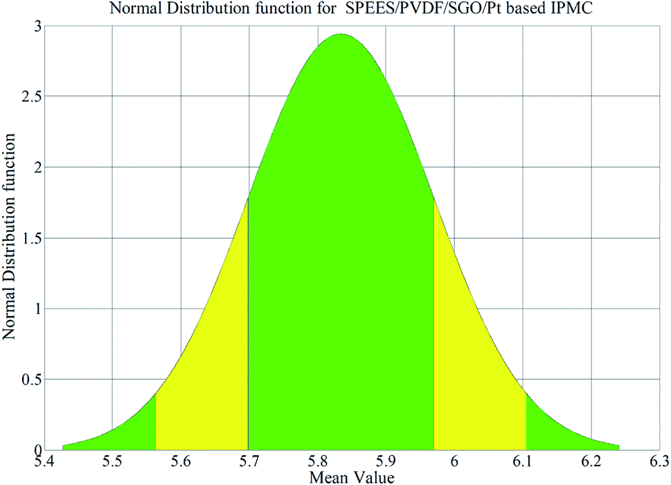
A digital weighing/load cell (Model: Citizen CX-220, Make: India) was used for load characterization of the IPMC membranes, where the tip of the SPEES/PVDF/Pt or SPEES/PVDF/SGO/Pt IPMC membrane touches the pan of the load cell while a voltage is applied through the NI-PXI System (ESI Fig. 2†). The maximum load carrying capabilities for the SPEES/PVDF/Pt and SPEES/PVDF/SGO/Pt IPMC membranes were 0.45 and 0.61 g, respectively, at 5 V DC. In order to assess the repeatability, several trials were conducted and the force data were noted ten times (ESI Tables 6 and 7†). The maximum bending displacement of the SPEES/PVDF/SGO/Pt IPMC membrane was 15.2 mm and its force generation capability was 5.83 mN higher than that of SPEES/PVDF/Pt. Out of these ten experimental values, the mean force values for both IPMC membranes were calculated and used to calculate the SDs. The SDs for the SPEES/PVDF/Pt and SPEES/PVDF/SGO/Pt IPMC membranes were found to be 0.445 and 0.135, respectively (ESI Tables 6 and 7†). The normal distribution function for the SPEES/PVDF/SGO/Pt IPMC was plotted, as shown in Fig. 14. The narrow shape of the normal distribution suggests that the SPEES/PVDF/SGO/Pt IPMC has less error and great repeatability of the forced behavior at 5 V DC.
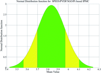 |
| | Fig. 14 Normal distribution function for the SPEES/PVDF/SGO/Pt-based IPMC. | |
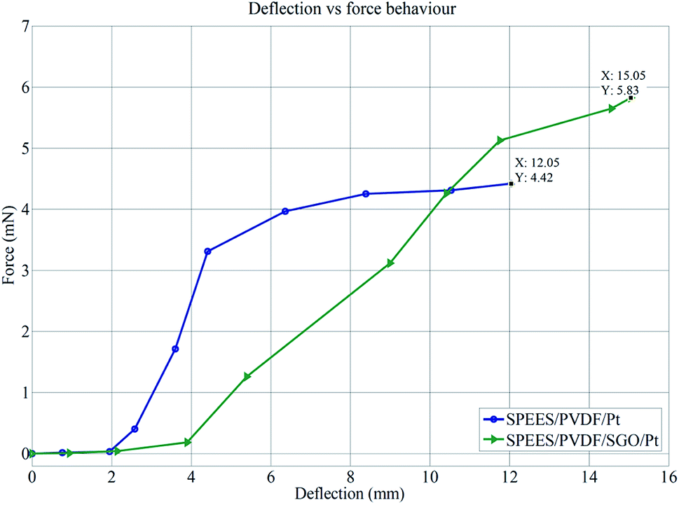
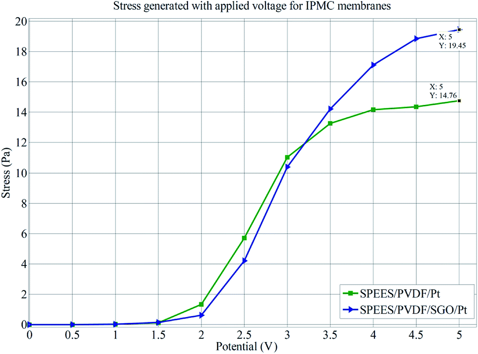
The load characterization analysis for the SPEES/PVDF/Pt and SPEES/PVDF/SGO/Pt IPMC membranes also confirmed that the bending force was indeed proportional to the electric field like the deflection, where the bending force was found to increase with an increase in the applied electric field intensity. Furthermore, Fig. 15 clearly shows that the deflection vs. force behavior of the SPEES/PVDF/Pt and SPEES/PVDF/SGO/Pt IPMC membranes was proportional to the applied electric voltage (0–5 V). The mechanical properties of SPEES/PVDF/Pt and SPEES/PVDF/SGO/Pt IPMCs were assessed by measuring the stress behavior with respect to the applied potential (Fig. 16). This study suggested that the generated stress values for both IPMCs increase with the increase in the applied voltage from 0–5 V DC. Fig. 16 also confirms that the stress generated up to an applied voltage of 1.5 V for SPEES/PVDF/Pt and SPEES/PVDF/SGO/Pt IPMCs was much less. Moreover, as the voltage was increased beyond 1.5 V, the generated stress for both IPMCs was found to be countable. The maximum stress values generated for the SPEES/PVDF/Pt and SPEES/PVDF/SGO/Pt IPMC membranes were found to be 14.76 and 19.45 Pa, respectively, under the applied voltage (Fig. 16). Thus, the results obtained from the electro-mechanical characterizations also confirm that the performance of the SPEES/PVDF/SGO/Pt-based IPMC was better than that of SPEES/PVDF/Pt IPMC, with respect to the large deflection, force and stress generation capability. A comparison between the different properties of the SPEES/PVDF/SGO/Pt-based IPMC membrane with those of Nafion and other reported IPMC actuators is given in Tables 4 and 5.
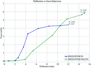 |
| | Fig. 15 Force vs. deflection behavior of SPEES/PVDF/Pt and SPEES/PVDF/SGO/Pt IPMCs. | |
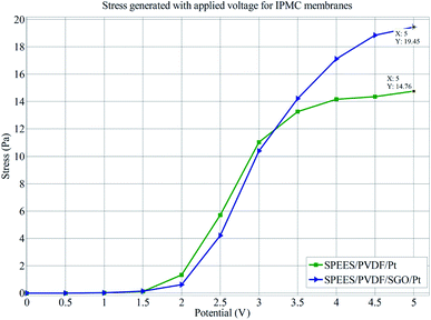 |
| | Fig. 16 Stress behavior of SPEES/PVDF/Pt and SPEES/PVDF/SGO/Pt IPMC membranes. | |
Table 4 Comparison between the properties of the SPEES/PVDF/SGO/Pt-based IPMC membrane actuator with those of other reported actuators
| Parameters |
SPEES/PVDF/SGO/Pt |
Kraton based IPMC11 |
Sulfonated polyetherimide54 |
Sulfonated polyvinyl alcohol8 |
Carbon nanotube–Nafion based actuator55 |
| PC (S cm−1) |
1.62 × 10⁻² |
1.30 × 10⁻³ |
1.40 × 10⁻³ |
1.60 × 10⁻³ |
5.70 × 10⁻³ |
| Current density (A cm−2) |
6.80 × 10⁻³ |
2.50 × 10⁻³ |
5.00 × 10⁻⁴ |
5.50 × 10⁻³ |
— |
| WU (%) |
78.00 |
233.00 |
26.40 |
82.30 |
25.10 |
| IEC (meq. g−1) |
1.95 |
2.00 |
0.55 |
1.20 |
0.71 |
| Tip displacement (mm) |
15.20 |
17.00 |
2.70 |
18.50 |
20.00 |
Table 5 Comparison between the SPEES/PVDF/SGO/Pt-based IPMC membrane actuator and Nafion-based IPMCs
| Parameters |
SPEES/PVDF/SGO/Pt |
Nafion-based IPMC56 |
Nafion-based IPMC16 |
SiO2-Nafion-based IPMC56 |
Nafion-based IPMC57 |
Nafion-based IPMC7 |
| IEC (meq. g−1) |
1.95 |
0.42 |
0.58 |
0.49 |
0.98 |
0.75 |
| Young's modulus (MPa) |
863 |
846 |
— |
727 |
— |
— |
| WH (%) |
78.00 |
— |
14.00 |
— |
16.70 |
16.20 |
| Current density (A cm−2) |
6.80 × 10⁻³ |
— |
∼1.2 × 10⁻⁴ |
— |
3 × 10⁻² |
2.40 × 10⁻⁵ |
| Tip displacement (mm) |
15.2 |
1.51 |
3.50 |
7.20 |
12.00 |
23.00 |
4. Conclusions
In this study, a high-performance electrochemical IPMC membrane actuator based on a SPEES/PVDF/SGO composite polymer material with a Pt electrode was fabricated using a simple solution casting method. The compatibility of PVDF with SPEES and SGO, through hydrogen bonding and electrostatic interactions between different kinds of oxygen-related functional groups, enabled the construction of extensive proton conducting channels, which facilitate proton diffusion.58 Therefore, hydrogen bonding provided much higher stiffness and mechanical strength for the fabricated IPMC membrane. The blending of SPEES, PVDF and SGO enhances the mechanical stability and leads to a better Young's modulus of 798.45 MPa for SPEES/PVDF/SGO than that of pristine SPEES (37.29 MPa). The current density of SPEES/PVDF/SGO/Pt was found to be 6.8 × 10⁻³ A cm−2 which facilitates ion accumulation and transmission, thus enhancing the actuation performance. Further, a stepwise tip deflection experiment was also carried out, where the maximum deflection was found to be 15 mm under 5 V DC. The deflection hysteresis behavior showed that there was deflection error with the repetition of the deflection experiment. This deflection error was controlled through a PD controller and minimized by up to 80%. The load characterization study suggested that the force generation capability of the SPEES/PVDF/SGO/Pt-based IPMC actuator was 5.83 mN at 5 V DC. The developed SPEES/PVDF/SGO/Pt-based IPMC actuator exhibited high actuation performance and better chemo-electro-mechanical properties compared with the SPEES/PVDF/Pt IPMC actuator. The results confirm that the addition of SGO improved the overall performance of the SPEES/PVDF/SGO/Pt-based IPMC. Beyond the good electromechanical properties, a normal distribution curve confirmed the superb repeatability of the SPEES/PVDF/SGO/Pt-based IPMC. Thus, the fabricated SPEES/PVDF/SGO/Pt-based IPMC holds great potential in the development of next-generation IPMC actuators for practical robotic and bio-mimetic applications.
Conflicts of interest
No conflicts.
Acknowledgements
The authors are grateful to the Director, CSIR-CMERI, Durgapur, India for granting the permission to publish this paper. This work was supported by the Science and Engineering Research Board (SERB), Department of Science & Technology, Government of India, under the research scheme National Post-Doctoral Fellowship awarded to Dr Ajahar Khan, Project Number: PDF/2016/002680.
References
- M. Rajagopalan and I. K. Oh, ACS Nano, 2011, 5, 2248–2256 CrossRef PubMed.
- E. Smela, Adv. Mater., 2003, 15, 481–494 CrossRef.
- K. Fukuda, T. Sekitani, U. Zschieschang, H. Klauk, K. Kuribara, T. Yokota, T. Sugino, K. Asaka, M. Ikeda, H. Kuwabara, T. Yamamoto, K. Takimiya, T. Fukushima, T. Aida, M. Takamiya, T. Sakurai and T. Someya, Adv. Funct. Mater., 2011, 21, 4019–4027 CrossRef.
- J. Lu, S. G. Kim, S. Lee and I.-K. Oh, Adv. Funct. Mater., 2008, 18, 1290–1298 CrossRef.
- J. Li, W. Ma, L. Song, Z. Niu, L. Cai, Q. Zeng, X. Zhang, H. Dong, D. Zhao, W. Zhou and S. Xie, Nano Lett., 2011, 11, 4636–4641 CrossRef PubMed.
- A. Khan, R. K. Jain, P. Banerjee, Inamuddin and A. M. Asiri, Mater. Res. Express, 2017, 4, 115701 CrossRef.
- Inamuddin, A. Khan, M. Luqman and A. Dutta, Sens. Actuators, A, 2014, 216, 295–300 CrossRef.
- Inamuddin, A. Khan, R. K. Jain and M. Naushad, Smart Mater. Struct., 2015, 24, 95003 CrossRef.
- M. Shahinpoor, Electrochim. Acta, 2003, 48, 2343–2353 CrossRef.
- A. Khan, Inamuddin and R. K. Jain, J. Appl. Polym. Sci., 2016, 133, 43787 CrossRef.
- A. Khan, Inamuddin, R. K. Jain and M. Naushad, RSC Adv., 2015, 5, 91564–91573 RSC.
- B. J. Akle, M. D. Bennett and D. J. Leo, Sens. Actuators, A, 2006, 126, 173–181 CrossRef.
- S.-W. Yeom and I.-K. Oh, Smart Mater. Struct., 2009, 18, 85002 CrossRef.
- Y. Haldorai and J.-J. Shim, New J. Chem., 2014, 38, 2653–2659 RSC.
- V. K. Nguyen and Y. Yoo, Sens. Actuators, B, 2007, 123, 183–190 CrossRef.
- L. Naji, M. Safari and S. Moaven, Carbon, 2016, 100, 243–257 CrossRef.
- M. Shahinpoor, K. J. Kim and D. J. Leo, Polym. Compos., 2003, 24, 24–33 CrossRef.
- M. Shahinpoor and K. J. Kim, Smart Mater. Struct., 2001, 10, 819–833 CrossRef.
- M. Safari, L. Naji, R. T. Baker and F. A. Taromi, Polymer, 2015, 76, 140–149 CrossRef.
- P. Maheswari, P. Barghava and D. Mohan, J. Polym. Res., 2013, 20, 74 CrossRef.
- Z. Xue, Y. Tang, X. Duan, Y. Ye, X. Xie and X. Zhou, Composites, Part A, 2016, 81, 13–21 CrossRef.
- M. J. Cunningham, D. F. L. Jenkins, W. W. Clegg and M. M. Bakush, Sens. Actuators, A, 1995, 50, 147–150 CrossRef.
- P. Audrain, P. Masson, A. Berry, J.-C. Pascal and B. Gazengel, J. Intell. Mater. Syst. Struct., 2004, 15, 319–327 CrossRef.
- J. Sirohi and I. Chopra, J. Intell. Mater. Syst. Struct., 2000, 11, 246–257 CrossRef.
- V. T. Rathod, D. R. Mahapatra, A. Jain and A. Gayathri, Sens. Actuators, A, 2010, 163, 164–171 CrossRef.
- L. Capineri, L. Masotti, V. Ferrari, D. Marioli, A. Taroni and M. Mazzoni, Rev. Sci. Instrum., 2004, 75, 4906–4910 CrossRef.
- C. Chang, V. H. Tran, J. Wang, Y.-K. Fuh and L. Lin, Nano Lett., 2010, 10, 726–731 CrossRef PubMed.
- J. Chang, M. Dommer, C. Chang and L. Lin, Nano Energy, 2012, 1, 356–371 CrossRef.
- E. Bormashenko, R. Pogreb, Y. Socol, M. H. Itzhaq, V. Streltsov, S. Sutovski, A. Sheshnev and Y. Bormashenko, Opt. Mater., 2004, 27, 429–434 CrossRef.
- V. Panwar, K. Cha, J.-O. Park and S. Park, Sens. Actuators, B, 2012, 161, 460–470 CrossRef.
- M. Celina, T. R. Dargaville, R. A. Assink and J. W. Martin, High Perform. Polym., 2005, 17, 575–592 CrossRef.
- V. Panwar, S. Y. Ko, J.-O. Park and S. Park, Sens. Actuators, B, 2013, 183, 504–517 CrossRef.
- K. S. Novoselov, Science, 2004, 306, 666–669 CrossRef PubMed.
- A. K. Geim and K. S. Novoselov, Nat. Mater., 2007, 6, 183–191 CrossRef PubMed.
- C. Lee, X. Wei, J. W. Kysar and J. Hone, Science, 2008, 321, 385–388 CrossRef PubMed.
- S. Stankovich, D. A. Dikin, R. D. Piner, K. A. Kohlhaas, A. Kleinhammes, Y. Jia, Y. Wu, S. T. Nguyen and R. S. Ruoff, Carbon, 2007, 45, 1558–1565 CrossRef.
- L. Zhang and G. Shi, J. Phys. Chem. C, 2011, 115, 17206–17212 CrossRef.
- Y. Xu, H. Bai, G. Lu, C. Li and G. Shi, J. Am. Chem. Soc., 2008, 130, 5856–5857 CrossRef PubMed.
- D. Li, M. B. Müller, S. Gilje, R. B. Kaner and G. G. Wallace, Nat. Nanotechnol., 2008, 3, 101–105 CrossRef PubMed.
- E. E. Unveren, T. Y. Inan and S. S. Çelebi, Fuel Cells, 2013, 13, 862–872 Search PubMed.
- E. E. Unveren, T. Erdogan, S. S. Çelebi and T. Y. Inan, Int. J. Hydrogen Energy, 2010, 35, 3736–3744 CrossRef.
- R. Y. M. Huang, P. Shao, C. M. Burns and X. Feng, J. Appl. Polym. Sci., 2001, 82, 2651–2660 CrossRef.
- Inamuddin, A. Khan, R. K. Jain and M. Naushad, J. Intell. Mater. Syst. Struct., 2016, 27, 1534–1546 CrossRef.
- A. Khan, Inamuddin, R. K. Jain and A. M. Asiri, Polym. Eng. Sci., 2017, 57, 258–267 CrossRef.
- W. Jang, S. Sundar, S. Choi, Y.-G. Shul and H. Han, J. Membr. Sci., 2006, 280, 321–329 CrossRef.
- K. Jung, J. Nam and H. Choi, Sens. Actuators, A, 2003, 107, 183–192 CrossRef.
- M. J. Han, J. H. Park, J. Y. Lee and J. Y. Jho, Macromol. Rapid Commun., 2006, 27, 219–222 CrossRef.
- C.-A. Dai, C.-J. Chang, A.-C. Kao, W.-B. Tsai, W.-S. Chen, W.-M. Liu, W.-P. Shih and C.-C. Ma, Sens. Actuators, A, 2009, 155, 152–162 CrossRef.
- I. A. Levitsky, P. Kanelos and W. B. Euler, J. Chem. Phys., 2004, 121, 1058–1065 CrossRef PubMed.
- V. Panwar, C. Lee, S. Y. Ko, J.-O. Park and S. Park, Mater. Chem. Phys., 2012, 135, 928–937 CrossRef.
- T.-G. Noh, Y. Tak, J.-D. Nam and H. Choi, Electrochim. Acta, 2002, 47, 2341–2346 CrossRef.
- Y. Wang, H. Chen, Y. Wang, Z. Zhu and D. Li, Electrochim. Acta, 2014, 129, 450–458 CrossRef.
- Q. Zhang, Y. Li, Y. Feng and W. Feng, Electrochim. Acta, 2013, 90, 95–100 CrossRef.
- M. Rajagopalan, J.-H. Jeon and I.-K. Oh, Sens. Actuators, B, 2010, 151, 198–204 CrossRef.
- H. Lian, W. Qian, L. Estevez, H. Liu, Y. Liu, T. Jiang, K. Wang, W. Guo and E. P. Giannelis, Sens. Actuators, B, 2011, 156, 187–193 CrossRef.
- D.-J. Guo, S.-J. Fu, W. Tan and Z.-D. Dai, J. Mater. Chem., 2010, 20, 10159 RSC.
- T. A. Zawodzinski, J. Electrochem. Soc., 1993, 140, 1041 CrossRef.
- M. Vinothkannan, A. R. Kim, G. Gnana kumar, J.-M. Yoon and D. J. Yoo, RSC Adv., 2017, 7, 39034–39048 RSC.
Footnote |
| † Electronic supplementary information (ESI) available. See DOI: 10.1039/c8ra03554g |
|
| This journal is © The Royal Society of Chemistry 2018 |
Click here to see how this site uses Cookies. View our privacy policy here. 
 Open Access Article
 This Open Access Article is licensed under a Creative Commons Attribution-Non Commercial 3.0 Unported Licence
 *a,
Bhaskar Ghosha,
Inamuddin
*a,
Bhaskar Ghosha,
Inamuddin