 Open Access Article
Creative Commons Attribution 3.0 Unported Licence
Facile synthesis and properties of a cation exchange membrane with bifunctional groups prepared by pre-irradiation graft copolymerization
Jianhua Zu *a,
Fangdong Tangb,
Linfeng Heb and
Lingxiao Fua
aSchool of Nuclear Science and Engineering, Shanghai Jiao Tong University, Shanghai 200240, China. E-mail: zujianhua@sjtu.edu.cn
bShanghai Institute of Measurement and Testing Technology, Shanghai 201203, China
First published on 19th July 2018
Abstract
A new type of a cation exchange membrane named ETFE-g-poly(AA-co-SSS) with bifunctional groups was synthesized by a one-step method. Its preparation by an electron beam-induced pre-irradiation grafting method and the effects of reaction temperature, monomer concentration, pH value of the grafting solution, storage time and temperature of the irradiated poly(ethylene-alt-tetrafluoroethylene) (ETFE) films on the grafting yield were studied. A total concentration of 2 mol L−1 of monomers was found to be beneficial for acrylic acid (AA) and sodium styrene sulfonate (SSS) co-grafting onto the ETFE films. Infrared spectroscopic analysis of the grafted membrane confirmed the existence of sulfonate and carboxylic acid groups. The contact angle of the grafted membrane decreased from 94.3 to 46.7° with the increase in grafting yield. The higher the grafting yield, the faster the response and recovery rate with respect to humidity. AFM images showed that the diameter of the grafted chains on the surface of ETFE membranes was about 30 nm. The voltage of the grafted membrane was stable after 100 cycles of charge–discharge; thus, the prepared membranes have great potentials to be used as separators in secondary batteries.
1. Introduction
Traditional cation exchange membranes are mostly prepared by physical blending or chemical copolymerization. Since 1971, the DuPont company has produced commercial ion exchange membranes named Nafion membranes with sulfonate groups. The membranes have low resistance and high stability, but their degradation rate is accelerated when the cathodic potential is relatively high.1 In addition, Nafion membranes also have the defects of high cost, low conductivity and poor resistance to methanol at high temperature.2 Radiation-induced graft polymerization is a promising method to introduce desirable properties onto polymers because of its simplicity in controlling the grafting parameters. Monomer or monomer mixtures with functional groups are grafted onto ready-made films so that the film shaping process can be excluded as the preparation begins with a polymer already in the film form.3 All membranes synthesized by the radiation-induced grafting technique have special advantages over other membranes prepared by blending or polymerization modification. Membranes prepared by this technique have wide applications in proton exchange membrane fuel cells,4 secondary batteries,5,6 and treatment of wastewater.7Although various efforts have been made to prepare high-performance membranes for ion exchange,8,9 so far, only few radiation-grafted ion exchange membranes have been successfully applied in batteries or fuel cells for large-scale commercialization because of a few key challenges; these include (1) radiation degradation of polyolefin and monomer polymerization initiated by radicals produced by radiation, and (2) the high cost of certain starting materials and irradiation facility. In China, for commercial development of ion exchange membranes, the membranes are mainly prepared by copolymerization induced by a chemical initiator. Researchers engaged in the membrane manufacturing technology have a background in polymer chemistry. In the next 5 to 10 years, we strongly believe that with continuous research in this field, great progress will be made towards the manufacture of radiation-grafted cation membranes and their applications in secondary batteries or fuel cells.
We have reported that the addition of acid plays a significant role in radiation-induced grafting of vinyl monomers such as sodium styrene sulfonate (SSS) and acrylic acid (AA) onto polyethylene.10 Based on our research, Nasef et al. further prepared proton exchange membranes containing only sulfonic acid groups by adding an aqueous acid solution to the grafting mixture.11 However, membranes with –SO3H groups can swell in water to a great extent due to their strong hydrophilicity, whereas membranes containing –COOH groups, which are weakly acidic and less hydrophilic, swell to a lesser extent in water. Patent applications and research done by Henkensmeier et al. have demonstrated that membranes having two different ion-exchange groups perform better than membranes having one type of an ion-exchange group.12,13 Our attempt aims at synthesizing membranes having more than one type of ion-exchange group so as to achieve better performance in secondary batteries or humidity sensors. In our previous study, we carried out grafting of AA and SSS comonomers onto high density polyethylene (HDPE) by the pre-irradiation technique, and we studied the effects of various reaction parameters on the degree of grafting.14,15 We used electron spin-resonance spectroscopy to study the stability of radicals formed on HDPE and poly(ethylene-alt-tetrafluoroethylene) (ETFE) films by electron beam irradiation. The results indicated that the trapped radicals at the crystalline region of ETFE were more stable than the radicals of HDPE under the same absorption doses and storage conditions. A further improvement is expected by changing the matrix from HDPE to partially fluorinated ETFE, which is commercially available for approximately 3€ per m2. In addition, our research team has been devoted to the development of low-cost and anti-degradation ion-exchange membranes by radiation-induced grafting methods. To improve the stability of the modified polymer, a partially fluorinated film has been chosen as the polymer matrix.16 Several advantages over perfluorinated films are identified such as superior mechanical properties,17 faster grafting kinetics due to higher monomer compatibility and less radiation-induced damage.18,19
Shkolnik et al. reported the difficulties in direct grafting of sodium styrene sulfonate (SSS) onto fluoropolymers by radiation-induced grafting because of the incompatibility between the highly ionized sulfonic acid groups and its hydration sphere and the hydrophobic polymer matrix.20 Hence, a two-step grafting method was reported for the preparation of ion-exchange membranes bearing sulfonic acid groups.21–24 First, styrene or substituted styrene monomers was grafted onto the polymer films and then, the grafted membrane was immersed into chlorosulfonic acid or sulfuric acid at a higher temperature to introduce sulfonic groups into the benzene ring.25–27 The physical strength of the membranes deteriorated because of strongly acidic reaction conditions. Therefore, to simplify the preparation process and to improve the mechanical properties of the obtained membranes, we designed a co-monomer graft system to directly introduce –SO3H and –COOH groups onto fluorinated films by a one-step grafting method. Hence, a detailed study on the influence of grafting parameters was performed for the grafting of acrylic acid (AA) and SSS onto ETFE films. The introduction of both –COOH and –SO3H groups onto ETFE films further improved the swelling property and sensitivity to humidity of the grafted membranes.
2. Experimental
2.1 Materials
ETFE films of 50 μm were purchased from Nowofol GmbH (Siegsdorf, Germany). Acrylic acid (AA) was obtained from Sinopharm Chemical Reagent Co. Ltd. AA was purified by reduced pressure distillation to remove any inhibitors. Sodium styrene sulfonate (SSS) was bought from Zibo Jinyuelong Chemical Ltd and used without purification. Commercial battery separator was bought from Shanghai Shilong Hi-Tech. Ltd.2.2 Equipment
A 2 MeV accelerator (GJ-2, Shanghai Xianfeng Electric Machinery Plant) was used to irradiate ETFE films. The structure and morphology of ungrafted and grafted membranes were characterized by FT-IR spectroscopy (IR200, Nicolit) and AFM (Multimode NanoscopeIIIa, Bruker), respectively. The pH value of the solution was determined with a pH meter (Seven compact™, Mettler Toledo Co., Ltd.).2.3 Experimental method
here, W0 and Wg are the weights of the ungrafted and grafted membranes, respectively. Before grafting, the thickness of the ETFE film was 50 μm. The thickness of the grafted membranes varied with Gt. For example, the thickness was 128 μm for Gt = 98.3%.
here, CNaOH is the concentration of NaOH (mol L−1), and VNaOH is the volume of NaOH (mL).
3. Results and discussion
3.1 The influence of reaction time on Gt and Gs
From Fig. 1, we can see that Gt and Gs increase with the increasing grafting time at fixed monomer concentration and molar ratio. During the grafting time from 1.5 to 4.5 h, Gt increases linearly with the reaction time. At the beginning, the grafting reaction occurs on the surface of the ETFE membranes and is controlled by the monomeric diffusion rate. AA is grafted onto ETFE and then, the hydrophilicity of ETFE membranes improves; therefore, both AA and SSS react with the radicals formed on the graft chains. Due to the increase in membrane swelling and monomer diffusion rate, different thicknesses of the ETFE films can be finally introduced for the AA and SSS monomers.28,29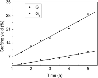 | ||
Fig. 1 Variation of Gt and Gs with reaction time. Total monomer concentration: 2 mol L−1; molar ratio of AA to SSS: 1![[thin space (1/6-em)]](https://www.rsc.org/images/entities/char_2009.gif) : :![[thin space (1/6-em)]](https://www.rsc.org/images/entities/char_2009.gif) 1; reaction temperature: 60 °C; absorbed dose: 150 kGy. 1; reaction temperature: 60 °C; absorbed dose: 150 kGy. | ||
3.2 The influence of monomer concentration on Gt
From Fig. 2, we can see that Gt increases from 2.9 to 84.6% when the monomer concentration varies from 0.8 to 3.2 mol L−1 at a fixed molar ratio. High monomer concentrations accelerate the diffusion rate of the monomers into the ETFE matrix so that more monomers can react with the radicals formed on ETFE by irradiation. However, it was reported that the grafting yield increased with the increasing monomer concentration to a certain value after which the grafting yield dropped with the increasing monomer concentration.30 In our grafting system, on one hand, SSS has limited solubility in the grafting solution; on the other hand, the homopolymerization or the copolymerization rate of monomers is slower than the grafting rate when monomer concentrations are lower than 3.2 mol L−1.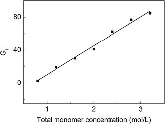 | ||
Fig. 2 Variation of Gt with total monomer concentration. Absorbed dose: 150 kGy; molar ratio of AA to SSS: 1![[thin space (1/6-em)]](https://www.rsc.org/images/entities/char_2009.gif) : :![[thin space (1/6-em)]](https://www.rsc.org/images/entities/char_2009.gif) 1; reaction temperature: 60 °C; reaction time: 5 h. 1; reaction temperature: 60 °C; reaction time: 5 h. | ||
3.3 The influence of reaction temperatures at different grafting times on Gt
Fig. 3 shows that Gt increases with an increase in temperature. Gt is less than 10% at 40 °C although the grafting reaction continues for 5 hours, which indicates that the diffusion rate of monomers to the ETFE matrix is very slow at 40 °C; therefore, the grafting reaction has long induction period under low temperature. When the grafting temperature is higher than 50 °C, Gt clearly increases with the increasing temperature due to greater membrane swelling and faster monomeric diffusion rate. After the grafting reaction is continued for 4.5 h, Gt almost levels off for all temperatures. After the introduction of hydrophilic –COOH and –SO3Na functional groups, the grafted membrane gradually swells in the grafting solution, which makes the graft chains highly movable within ETFE. In this case, the termination rate of the growing chains by mutual combination is accelerated.31 A similar tendency has also been reported for the grafting of styrene onto ETFE-based films.32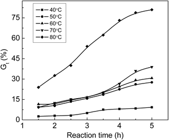 | ||
Fig. 3 Variation of Gt with time at various temperatures. Absorbed dose: 150 kGy; molar ratio of AA to SSS: 1![[thin space (1/6-em)]](https://www.rsc.org/images/entities/char_2009.gif) : :![[thin space (1/6-em)]](https://www.rsc.org/images/entities/char_2009.gif) 1; total monomer concentration: 2 mol L−1. 1; total monomer concentration: 2 mol L−1. | ||
3.4 The influence of pH values of the grafting solution on Gt
Additives such as acids and metal salts were used in the radiation grafting system. Acidic additives seemed to have a very important effect on the grafting yield. Different acids were added to the grafting solution to improve the grafting yield and lower the cost of the prepared functional materials. To enhance the grafting yield, the addition of inorganic acids is applicable to many grafting systems.33,34 The relationship between Gt and pH is shown in Fig. 4. The original pH value of the solution without adding HCl was 2.67. We obtained a pH value of 4.27 by dripping 0.1 mol L−1 NaOH solution into the grafting system. It was found that Gt was 49.8% at pH of 0.49, and it dropped to 12.9% when pH was 4.27. We found that the viscosity of the solution at pH = 0.49 was higher than that of the solution at pH = 4.27 when the grafted membranes were removed from the solution. The movement of the grafted chain with high molecular weight was restricted due to high viscosity of the grafting solution. Meanwhile, the monomers and their homopolymers with low molecular weights could freely diffuse and react with the growing grafted chains. The propagation rate of the grafted chains was faster than their termination rate; thus, Gt increased rapidly at pH = 0.49. The increase in grafting yield in simultaneous irradiation grafting systems by adding an inorganic acid was concluded based on the assumption that the addition of acid accelerated hydrogen abstraction by the monomers from nearby polymer molecules.35 For the pre-irradiation grafting system, research work done by Garnett indicated that the acid enhancement in the grafting yield was due to a partitioning effect.36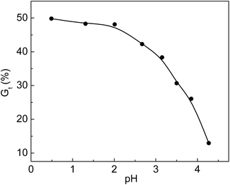 | ||
Fig. 4 Variation of Gt with pH value. Total monomer concentration: 2 mol L−1; molar ratio of AA to SSS: 1![[thin space (1/6-em)]](https://www.rsc.org/images/entities/char_2009.gif) : :![[thin space (1/6-em)]](https://www.rsc.org/images/entities/char_2009.gif) 1; reaction temperature: 60 °C; absorbed dose: 150 kGy; reaction time: 3 h. 1; reaction temperature: 60 °C; absorbed dose: 150 kGy; reaction time: 3 h. | ||
3.5 The influence of storage time of irradiated membranes on Gt
ETFE films irradiated with an electron beam in a nitrogen atmosphere were stored at −19 °C for different storage times and reacted with monomers at 80 °C. The relationship between Gt and storage time is shown in Fig. 5. Gt was 50.0% when the grafting reaction was carried out immediately after irradiation. Under the same reaction conditions, the Gt values dropped to 43.8% and 31.9% during 6 and 15 days of storage times, respectively. The trapped radicals formed in the ETFE film decayed with longer storage times. The lower the storage temperature, the longer is the lifetime of the radicals. Gupta et al. found that the grafting yield of an FEP film remained almost unchanged after 118 days of storage time at a temperature of −60 °C.37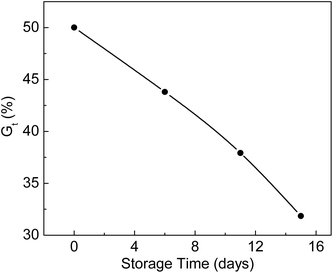 | ||
Fig. 5 Variation of Gt with storage time. Absorbed dose: 150 kGy; molar ratio of AA to SSS: 2![[thin space (1/6-em)]](https://www.rsc.org/images/entities/char_2009.gif) : :![[thin space (1/6-em)]](https://www.rsc.org/images/entities/char_2009.gif) 1; total monomer concentration: 2 mol L−1; reaction time: 2 h. 1; total monomer concentration: 2 mol L−1; reaction time: 2 h. | ||
4. Characterization of grafted membranes
4.1 FTIR test of grafted membranes
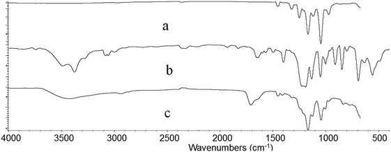
Fig. 6 shows the FTIR spectra of irradiated ETFE film (a), ETFE film grafted with AA having 98.3% grafting yield (b) and ETFE film grafted with AA and SSS with 141% grafting yield (c). Comparing the spectrum (a) with (b), a broad absorption peak between 3200 and 3650 cm−1 is seen, which is a characteristic peak for –OH stretching vibrations of AA. The absorption peak at 1732 cm−1 corresponds to the C![[double bond, length as m-dash]](https://www.rsc.org/images/entities/char_e001.gif) O groups of AA. For the spectrum of ETFE-g-poly(AA-co-SSS) membrane (c) compared with spectrum (a), the absorption peak at 842 cm−1 is the characteristic peak of a substituent attached to the para-position of benzene ring. The peak at 1044 cm−1 is due to a symmetrical stretching vibration of S
O groups of AA. For the spectrum of ETFE-g-poly(AA-co-SSS) membrane (c) compared with spectrum (a), the absorption peak at 842 cm−1 is the characteristic peak of a substituent attached to the para-position of benzene ring. The peak at 1044 cm−1 is due to a symmetrical stretching vibration of S![[double bond, length as m-dash]](https://www.rsc.org/images/entities/char_e001.gif) O.38 All these new adsorption peaks indicate that AA and SSS have been successfully grafted onto the ETFE film.
O.38 All these new adsorption peaks indicate that AA and SSS have been successfully grafted onto the ETFE film.
4.2 AFM test of grafted membranes
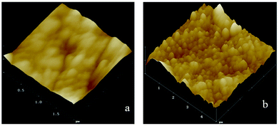
The surface roughness and topography of original ETFE and grafted membranes were tested by an Atomic Force Microscope (AFM) equipped with the nanoscope analysis software (Multimode NanoscopeIIIa) at room temperature. The AFM test was performed in a tapping mode, and a measurement of roughness of the 3-D surface was estimated. Fig. 7 shows AFM images for the surface morphology of the irradiated ETFE film (a) and the ETFE-g-poly(AA-co-SSS) membrane with Gt = 39.6% (b). Comparing the image (a) with (b), we inferred that the surface of the membrane became thicker and rougher because of the formation of grafted chains on the ETFE surface. The diameter of the grafted chains measured from the 3-D images was about 30 nm.4.3 The influence of grafting yield on contact angles
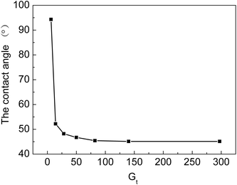
From Fig. 8, we can see that water contact angles first decrease with an increase in Gt and then, they almost level off with a further increase in Gt. The contact angle decreases from 94.3 to 46.7° when Gt rises from 6.3% to 50%. At the beginning of the grafting reaction, the hydrophilic grafted chains, which contain –COOH and –SO3H groups, only cover part of the surface of the membranes. When Gt is higher than 50%, the grafting chains are uniformly distributed on the surface of the grafted ETFE, due to which the contact angle remains almost unchanged. When Gt is higher than 50%, the graft reaction mainly occurs at a different depth of ETFE films. The hydrophilicity of the cation exchange membranes has a significant effect on their ionic conductivity. If the grafting yield is low or only parts of the ETFE film are grafted, ion-exchange groups are distributed inhomogeneously on the membrane. Furthermore, the hydrophilicity of the membrane also influences other performance characteristics, for example, compatibility, dimensional stability and resistance to methanol at high temperature when the membrane is used in a proton exchange fuel cell. To prepare cation exchange membranes with long-term stability, hydrophilicity of the membrane should be optimized by changing the grafting conditions.4.4 Electrochemistry performance of grafted membrane
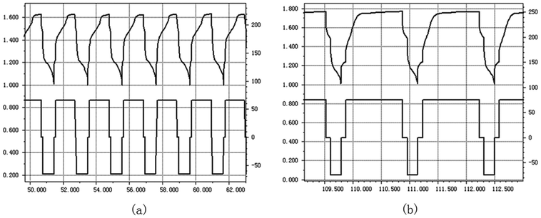
The grafted ETFE membrane with Gt = 135% and a commercial battery separator were separately assembled within batteries, and their electrochemistry performances were tested by charging and discharging cycles. The battery electrode was wrapped by a grafted membrane or a commercial battery separator and then soaked into 6 mol L−1 KOH solution. After activating for 8 h, the electrochemistry performance of the assembled batteries was tested. Fig. 9(a) and (b) show parts of the charge and discharge spectra of the grafted membrane and the commercial separator, respectively. The whole test was performed at an electric current of 66 mA for 200 h. For the grafted membrane, the charging voltage dropped from 1.66 V to 1.60 V. For the commercial separator, the charging voltage reduced from 1.83 V to 1.77 V. A lower charging voltage indicates that the resistance of the grafted membrane is lower than that of the commercial separator under the same test conditions. Low resistance is very important for grafted membranes used as battery separators, because the lower the film resistance, the greater the current when the battery is discharging. Furthermore, after 100 cycles of charging and discharging, the charging voltage was still relatively stable. Thus, the prepared ETFE-g-poly(AA-co-SSS) membranes have great potentials to be used as separators in secondary batteries.4.5 The relationship between Gt and alkali absorption property
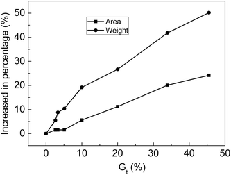
The membranes with Gt = 0, 2.6, 3.3, 5.1, 10.0, 20.0, 33.9 and 45.5% were soaked in 30% NaOH solution for 24 h at 25 °C and then taken out. After water on the surface of membranes was wiped off, the area and weight of the membrane were measured. The relationship between the increase in the percentage of weight or area is shown in Fig. 10. After the membranes were swollen in 30% NaOH solution, the area and weight of the membranes clearly increased with increasing Gt. Alkali absorption property is another key factor for evaluating the performance of ion-exchange membranes as separators of alkaline batteries. Because the membranes synthesized in this research contained both strong and weak acid groups when compared with membranes with only carboxylic acid groups, the alkali absorption rate was significantly improved.4.6 Influence of environmental humidity on the resistance of grafted membranes
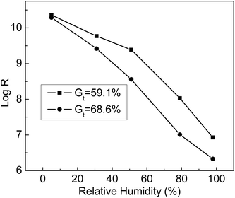
The humidity sensitivity curves of ETFE-g-poly(AA-co-SSS) membranes with different Gt values were measured at 25 °C at the following humidity values: 5%, 31%, 51%,79%, and 98%. From Fig. 11, we can see that the resistance of the grafting membranes (R) decreased with the increase in environmental humidity. At the same humidity, the resistance of the membrane with Gt = 68.6% was lower than that of the membrane with Gt = 59.1%. When Gt increased, more –COOH and –SO3Na groups grafted onto ETFE membranes were ionized at high humidity. When the humidity was 98%, the membrane resistance dropped by 4 orders of magnitude compared with that at humidity of 5%. All the results indicated that the grafting membranes with hydrophilic –COOH and –SO3Na groups responded quickly to the change in humidity. Therefore, the prepared membrane with bifunctional groups can be used as a humidity sensitive material of a humidity sensor.4.7 Response and recovery curves of grafted membranes
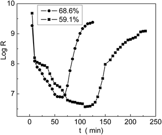
The grafted membrane was first placed in a container with 5% humidity until the resistance reached equilibrium; then, it was transferred to another container with 98% humidity. We found that the resistance decreased sharply in a short time and then leveled off. In the meantime, we recorded the resistance values and obtained the first half of a log![[thin space (1/6-em)]](https://www.rsc.org/images/entities/char_2009.gif) R–t curve, which is called the response curve. Then, the membrane was taken out of the container with 98% humidity and placed back into the container with 5% humidity. The membrane resistance rapidly increased and finally reached equilibrium. The second half of the log
R–t curve, which is called the response curve. Then, the membrane was taken out of the container with 98% humidity and placed back into the container with 5% humidity. The membrane resistance rapidly increased and finally reached equilibrium. The second half of the log![[thin space (1/6-em)]](https://www.rsc.org/images/entities/char_2009.gif) R–t curve was named as the recovery curve. The entire curve including the response and recovery processes is shown in Fig. 12; we can see that the membrane with 68.6% grafting yield responded and recovered more rapidly than the membrane with 59.1% grafting yield. In comparison with the result reported by Sangthumchai,39 the total response and recovery time of our prepared membrane with bifunctional groups –COOH and –SO3Na were shorter than those of a membrane that contained only –SO3Na groups. Due to weak interactions between the –COOH groups and absorbed H2O, the adsorbed H2O was easily desorbed; thus, the total response and recovery time became shorter.
R–t curve was named as the recovery curve. The entire curve including the response and recovery processes is shown in Fig. 12; we can see that the membrane with 68.6% grafting yield responded and recovered more rapidly than the membrane with 59.1% grafting yield. In comparison with the result reported by Sangthumchai,39 the total response and recovery time of our prepared membrane with bifunctional groups –COOH and –SO3Na were shorter than those of a membrane that contained only –SO3Na groups. Due to weak interactions between the –COOH groups and absorbed H2O, the adsorbed H2O was easily desorbed; thus, the total response and recovery time became shorter.
5. Conclusion
Radiation-grafted cation exchange membranes were prepared by a one-step method to investigate the effect of bifunctional groups on the properties of the membranes. New absorption peaks assigned to C![[double bond, length as m-dash]](https://www.rsc.org/images/entities/char_e001.gif) O and S
O and S![[double bond, length as m-dash]](https://www.rsc.org/images/entities/char_e001.gif) O indicated that the monomers AA and SSS were grafted onto ETFE membranes. When the grafting reaction was carried out at 80 °C, the highest grafting rate and Gt were obtained. The addition of HCl was an effective method for the enhancement of Gt and Gs. When irradiated ETFE films were kept at −19 °C, the decay rate of trapped radicals was very slow; thus, Gt dropped from 50.0 to 43.8% during a period of 144 h storage time.
O indicated that the monomers AA and SSS were grafted onto ETFE membranes. When the grafting reaction was carried out at 80 °C, the highest grafting rate and Gt were obtained. The addition of HCl was an effective method for the enhancement of Gt and Gs. When irradiated ETFE films were kept at −19 °C, the decay rate of trapped radicals was very slow; thus, Gt dropped from 50.0 to 43.8% during a period of 144 h storage time.
After the introduction of –COOH and –SO3Na groups, the grafting membranes not only exhibited excellent hydrophilicity but also showed high alkali uptake values. The resistance of the membranes decreased by 4 orders of magnitude at high humidity and therefore, the grafting membranes can be used as humidity sensitive materials for humidity sensors. The membranes with bifunctional groups displayed shorter response and recovery times compared to the ones containing only –SO3H groups. The charging voltage of the grafted membrane was lower than that of a commercial separator that only contained carboxylic acid groups. Furthermore, the charging voltage was still relatively stable after 100 cycles; therefore, the grafting membranes have great potentials to be used as separators in secondary batteries.
Conflicts of interest
There are no conflicts to declare.Acknowledgements
The authors wish to acknowledge the financial support from National Natural Science Foundation of China (Grant No. 11675103, 91226111).Notes and references
- N. Ramaswamy, N. Hakim and S. Mukerjee, Electrochim. Acta, 2008, 53, 3279–3295 CrossRef.
- J. B. Hou, H. M. Yu and L. A. Wang, J. Power Sources, 2008, 180, 232–237 CrossRef.
- M. M. Nasef and E.-S. Hegazy, Prog. Polym. Sci., 2004, 29, 499–561 CrossRef.
- Y. Ma, Y. X. Wang and X. J. Deng, RSC Adv., 2017, 39676–39684 RSC.
- E. Yusafronova, D. V. Golubenko and N. V. Shevlyakova, J. Membr. Sci., 2016, 515, 196–203 CrossRef.
- Z. P. Zhao, Z. P. Zhou, J. B. Zhou and F. Xie, Int. J. Electrochem. Sci., 2015, 10, 4303–4313 Search PubMed.
- B. S. Kaith, J. Dhiman and J. K. Bhatia, RSC Adv., 2015, 50, 39771–39784 RSC.
- G. Merle, M. Wessling and K. Nijmeijer, J. Membr. Sci., 2011, 377, 1–35 CrossRef.
- M. Valiollah, N. Meissam, M. Alam and A. Reza, Int. J. Electrochem. Sci., 2016, 11, 5302–5317 Search PubMed.
- J. H. Zu, Z. P. Hu and W. T. Wang, J. Radioanal. Nucl. Chem., 2007, 273, 479–484 CrossRef.
- M. M. Nasef, H. Saidi and K. Z. M. Dahlan, J. Appl. Polym. Sci., 2010, 118, 2801–2809 CrossRef.
- D. Henkensmeier, H. B. youcef, F. Wallasch and L. Gubler, J. Membr. Sci., 2013, 447, 228–235 CrossRef.
- M. Seko, S. Ogawa and K. Kimoto, ACS Symp. Ser., 1982, 365, 180 Search PubMed.
- J. H. Zu, M. H. Wu, J. Q. Zhang, C. H. Yu, X. W. Liu and L. Tong, J. Appl. Polym. Sci., 2006, 99, 3401–3405 CrossRef.
- J. H. Zu, C. H. Yu, M. H. Wu, Z. Jiao, J. Q. Zhang and X. W. Liu, J. Appl. Polym. Sci., 2006, 99, 3396–3400 CrossRef.
- M. M. Nasef, H. Saidi and K. Z. Dahlan, Radiat. Phys. Chem., 2003, 68, 875–883 CrossRef.
- I. Giulmeau, S. Esnouf, N. Betz and A. Lemoel, Nucl. Instrum. Methods Phys. Res., Sect. B, 1997, 131, 270–275 CrossRef.
- T. Dargaville, G. George, D. Hill and A. Whittaker, Prog. Polym. Sci., 2003, 28, 1355–1376 CrossRef.
- L. Gubler, H. Benyoucef, S. Alkangürsel, A. Wokaun and G. G. Scherer, ECS Trans., 2007, 11, 27–34 Search PubMed.
- S. Shkolnik and D. Behar, J. Appl. Polym. Sci., 1982, 27, 2189–2196 CrossRef.
- L. F. Li, B. Deng, Y. L. Li, Y. Yu, L. D. Xie, J. Y. Li and X. F. Lu, J. Membr. Sci., 2010, 346, 113–120 CrossRef.
- M. M. Nasef, H. Saidi and K. Z. M. Dahlan, Nucl. Instrum. Methods Phys. Res., Sect. B, 2007, 265, 168–172 CrossRef.
- M. Shen, S. Roy, J. W. Kuhlmann, K. Scott, K. Lovell and J. A. Horsfall, J. Membr. Sci., 2005, 251, 121–130 CrossRef.
- F. Y. Yu and J. J Hu, Int. J. Electrochem. Sci., 2016, 11, 724–737 Search PubMed.
- S. Phadnis, M. Patri, V. R. Hande and P. C. Deb, J. Appl. Polym. Sci., 2003, 90, 2572–2577 CrossRef.
- S. Phadnis, M. Patri, V. R. Hande, S. Roychoudhury and P. C. Deb, J. Appl. Polym. Sci., 2004, 92, 2318–2325 CrossRef.
- K. Jetsrisuparb, S. Balog, C. Bas, L. Perrin, A. Wokaun and L. Gubler, Eur. Polym. J., 2014, 53, 75–89 CrossRef.
- I. Giulmeau, S. Esnouf, N. Betz and A. Lemoel, Nucl. Instrum. Methods Phys. Res., Sect. B, 1997, 131, 270–275 CrossRef.
- T. Dargaville, G. George, D. Hill and A. Whittaker, Prog. Polym. Sci., 2003, 28, 1355–1376 CrossRef.
- R. Rohani, M. M. Nasef, H. Saidi and K. Z. M. Dahlan, Chem. Eng. J., 2007, 132, 27–35 CrossRef.
- D. Maldas, PhD thesis, University of Calcutta, 1983.
- H. P. Brack, H. G. Buhrer, L. Bonorand and G. G. Scherer, J. Mater. Chem., 2000, 10, 1795–1803 RSC.
- N. B. El-Assy, J. Appl. Polym. Sci., 1991, 42, 885–889 CrossRef.
- M. M. Nasef, H. Saidi, H. M Nor, K. M. Dahlan and K. Hashim, Nucl. Sci. J. Malays., 1999, 17, 45–56 Search PubMed.
- S. H. Choi and Y. Nho, Radiat. Phys. Chem., 2000, 58, 157–168 CrossRef.
- J. Garnett, S. Jankiewicz, M. Long and D. Sangster, J. Polym. Sci., Polym. Lett. Ed., 1985, 23, 563–566 CrossRef.
- B. Gupta, F. Buchi and G. Scherer, J. Polym. Sci., Part A: Polym. Chem., 1994, 32, 1931–1938 CrossRef.
- R. Q. Li, G. L. Fan and R. L. Qu, Spectral Analysis of Organic Structures, Tianjin University Press, Tianjin, 2002, p. 48 Search PubMed.
- T. Sangthumchai, S. Youngme and S. Martwiset, J. Appl. Polym. Sci., 2017, 134, 45411 CrossRef.
| This journal is © The Royal Society of Chemistry 2018 |


