 Open Access Article
Laboratory evaluation and numerical simulation of the alkali–surfactant–polymer synergistic mechanism in chemical flooding
Fuzhen Chenab,
Jianwei Gu *a,
Hanqiao Jiangb,
Xue Yaoa and
Yuan Lia
aSchool of Petroleum Engineering, China University of Petroleum, Qingdao, China 266580. E-mail: gujianweicup@sina.cn; Tel: +86 18554878108
bState Key Laboratory of Petroleum Resources and Prospecting, China University of Petroleum, Beijing, China 102249
First published on 25th July 2018
Abstract
Alkali–surfactant–polymer (ASP) flooding, which can reduce interfacial tension (IFT) and the mobility ratio between oil and water phases, has been proven to be effective for enhancing oil recovery in laboratory experiments and field pilots. However, the study of interactions within alkali–surfactant–polymers for chemical flooding is neither comprehensive nor complete until now. Laboratory experiments were conducted and a corresponding numerical simulation model was established to characterize multiple component interactions during the ASP flooding process. Synergistic effects of multiple component interactions on viscosity variation, IFT reduction, and multicomponent adsorption were studied separately. ASP solution viscosity shows non-linear variation behavior with an increasing polymer concentration. Alkali decreases the molecular hydraulic radius of a polymer, and then limits its contribution to viscosity. Oil–water interfacial tension decreases with the join in of polymer which can act as an alternative effect to replace surfactant adsorbed on a mineral surface. Petroleum acid will react with alkali and produce petroleum soap to perform a synergetic action with the surfactant on IFT reduction. Adsorption fraction and diffusion rate of a surfactant will diminish due to rheology improvements caused by a polymer. Alkali can protect a surfactant from adsorption consumption by competitive adsorption. A viscosity non-linear logarithm mixing method, IFT reduction–relative permeability curve interpolation method, and a multicomponent adsorption isotherm model were developed to characterize and simulate the synergistic effects obtained by experiments. A novel ASP flooding numerical simulation model was constructed which coupled the synergistic effects simulation methods of viscosity variation, IFT reduction, and multicomponent adsorption. The numerical simulation result based on the proposed model has better agreement with experiment results compared with that of the traditional model. Validation results proved the effectiveness of the proposed model which can be used to enhance a synergistic mechanism study and field application of ASP flooding.
1. Introduction
Laboratory research conducted by Lin et al. in 1987 indicated that oil recovery can be improved by using a combination of alkali, surfactant, and polymer.1 After that, ASP flooding technology which can improve mobility ratio and sweep efficiency of remaining oil has been reported on a world scale with a high proportion of success.2–6 The effect of alkali on ASP flooding was studied by Nasr-EI-Din et al. and they indicated that residual oil was recovered by two mechanisms: low interfacial tension and wettability reversal.7 An alkali agent will react with acid to generate an in situ surfactant and, hence, attain ultralow interfacial tension.8–11 The role of a polymer is to increase viscosity, hence reducing the mobility ratio and reaching greater volumetric sweep efficiency.12,13 The surfactant component of a system is responsible for reducing IFT between oil and water phases to a level that promotes mobilization of trapped oil drops.14,15 Viscoelasticity theory was developed by Hou et al. to describe the mechanism of ASP flooding. They considered viscoelasticity rather than IFT as an evaluation index to study and optimize ASP flooding.16 Different from sandstone reservoirs, carbonate reservoirs usually are oil-wet, an unfavorable condition for ASP flooding. However, Bortolotti et al. and Levitt et al. evaluated the effects of ASP flooding on carbonate rocks in laboratory experiments. The results showed that ASP flooding was effective for enhancing ultimate oil recovery in oil-wet carbonate reservoirs.17,18Numerical simulation software was developed based on dozens of years of phase behavior, core flood, and mechanistic research on ASP flooding. The University of Texas Chemical Compositional Simulator (UTCHEM) was usually used to model ASP flooding process.19,20 Yuan et al. established a 3D multifunctional compositional numerical simulator to study and predict the outcomes of ASP flooding.21 Using commercial simulation software CMG to design and simulate field pilot, Moreno et al. and Van et al. indicated that it is possible to increase oil recovery dramatically by ASP flooding.22,23 Farajzadeh et al. coupled a multi-purpose dynamic reservoir simulator (MoReS) and geochemistry software program (PHREEQC) to provide a versatile tool for ASP flooding numerical simulation.24
Pilot tests and field applications of ASP flooding have been carried out around the world. ASP flooding technology has been proven successful in three completed projects in North America.25 Vargo et al. reported that an ASP flooding project in the Cambridge Minnelusa field was a technical and economic success with an ultimate incremental oil recovery of 28.1%.26 In China, the first ASP flooding pilot was conducted in the Shengli oilfield in 1992 and the incremental oil recovery was reported to be 26% OOIP.27 Wang et al. indicated that five ASP flooding pilots were conducted in the Daqing oilfield and the oil recoveries of four of them were 20% OOIP above those obtained with water flooding.28
It should be mentioned that an alkali–surfactant–polymer will affect each other more or less rather than noninterference during a multicomponent flooding process, and those interactions are usually synergistic effects. However, a synergistic effect which can restrain or enhance ASP flooding performance hasn't attracted enough attention until now. The study of synergistic effects for ASP flooding is neither comprehensive nor complete according to our knowledge. Given the reasons mentioned above, our goal was to investigate an alkali–surfactant–polymer synergistic effect based on laboratory experiments, and then establish a corresponding numerical simulation model with the synergistic mechanism combined to describe the multiple component's interactions during the ASP flooding process.
2. Experimental design
2.1. Material descriptions
Artificial homogeneous cores were used in ASP flooding tests. Relative parameters of artificial cores were designed based on formation properties of the Lvda offshore oilfield in Bohai Bay in China. A total of 50 cores with dimensions of 2.50 cm diameter and 10.00 cm length were prepared. The approximate porosity and permeability of each core was 0.28 and 1750 mD, respectively. Crude oil, injection water, and formation brine used in this study were collected from the Lvda oilfield. Crude oil density and viscosity were 866 kg m−3 and 57.13 mPa at atmospheric pressure and a temperature of 25 °C. Compositions of injection water and formation brine are shown in Table 1. The alkali used in this study was pure sodium hydroxide (NaOH).29 Sodium dodecyl sulfate with an active content of 85.0 wt% was chosen as the surfactant in the ASP agent system. A high molecular weight polyacrylamide (HPAM, 24.0% hydrolyzed and molecular mass of 11.6 million daltons) was used as the polymer in this study.| Parameter | Concentration (mg L−1) | |
|---|---|---|
| Injection water | Formation brine | |
| Calcium | 190 | 683 |
| Magnesium | 96 | 113 |
| Sodium | 1192 | 3133 |
| Bicarbonate | 30 | 161 |
| Chloride | 2096 | 5473 |
| Sulphate | 408 | 234 |
| Total dissolved solids | 4011 | 9797 |
2.2. Experimental plan
Two groups of core flooding experiments were designed as shown in Tables 2 and 3. The aim of the experiments in Table 2 was to study the characteristic of ASP flooding and then compare the performances of unitary, binary, and ternary chemical flooding. Effects of alkali and polymer on surfactant adsorption were measured by experiments and listed in Table 3.| Core number | Initial water slug volume (PV) | ASP slug volume (PV) | Porosity (%) | Permeability (mD) | Initial oil saturation (%) | Concentration (wt%) | ||
|---|---|---|---|---|---|---|---|---|
| Surfactant | Alkali | Polymer | ||||||
| 1 | 0.08 | 0.43 | 28.34 | 1817.10 | 73.13 | 0.25 | 1.0 | 0.12 |
| 2 | 0.26 | 0.43 | 32.03 | 1573.20 | 73.00 | 0.25 | 1.0 | 0.12 |
| 3 | 0.92 | 0.43 | 28.72 | 1557.90 | 74.44 | 0.25 | 1.0 | 0.12 |
| 4 | 0.32 | 0.43 | 29.82 | 1751.26 | 72.86 | — | 1.0 | — |
| 5 | 0.32 | 0.43 | 28.35 | 1680.10 | 73.31 | 0.25 | — | — |
| 6 | 0.32 | 0.43 | 28.68 | 1682.27 | 71.59 | — | — | 0.12 |
| 7 | 0.32 | 0.43 | 29.45 | 1759.64 | 72.56 | 0.25 | 1.0 | — |
| 8 | 0.32 | 0.43 | 27.89 | 1823.59 | 73.15 | — | 1.0 | 0.12 |
| 9 | 0.32 | 0.43 | 28.64 | 1789.33 | 72.89 | 0.25 | — | 0.12 |
| 10 | 0.32 | 0.43 | 28.76 | 1698.25 | 73.21 | 0.25 | 1.0 | 0.12 |
| Core number | Concentration (wt%) | Core number | Concentration (wt%) | ||||
|---|---|---|---|---|---|---|---|
| Surfactant | Alkali | Polymer | Surfactant | Alkali | Polymer | ||
| 11 | 0.1 | — | — | 31 | 0.1 | — | — |
| 12 | 0.1 | — | 0.08 | 32 | 0.1 | 0.75 | — |
| 13 | 0.1 | — | 0.16 | 33 | 0.1 | 1.5 | — |
| 14 | 0.1 | — | 0.24 | 34 | 0.1 | 2 | — |
| 15 | 0.2 | — | — | 35 | 0.2 | — | — |
| 16 | 0.2 | — | 0.08 | 36 | 0.2 | 0.75 | — |
| 17 | 0.2 | — | 0.16 | 37 | 0.2 | 1.5 | — |
| 18 | 0.2 | — | 0.24 | 38 | 0.2 | 2 | — |
| 19 | 0.3 | — | — | 39 | 0.3 | — | — |
| 20 | 0.3 | — | 0.08 | 40 | 0.3 | 0.75 | — |
| 21 | 0.3 | — | 0.16 | 41 | 0.3 | 1.5 | — |
| 22 | 0.3 | — | 0.24 | 42 | 0.3 | 2 | — |
| 23 | 0.4 | — | — | 43 | 0.4 | — | — |
| 24 | 0.4 | — | 0.08 | 44 | 0.4 | 0.75 | — |
| 25 | 0.4 | — | 0.16 | 45 | 0.4 | 1.5 | — |
| 26 | 0.4 | — | 0.24 | 46 | 0.4 | 2 | — |
| 27 | 0.5 | — | — | 47 | 0.5 | — | — |
| 28 | 0.5 | — | 0.08 | 48 | 0.5 | 0.75 | — |
| 29 | 0.5 | — | 0.16 | 49 | 0.5 | 1.5 | — |
| 30 | 0.5 | — | 0.24 | 50 | 0.5 | 2 | — |
2.3. Experimental apparatus and procedure
(1) Inserted one core into core holder and a confining pressure of 5.0 MPa was applied.
(2) 5.0 pore volumes (PVs) of formation brine were injected into the core with an injection rate of 0.3 mL min−1. Water flooding permeability was measured.
(3) 5.0 PVs of crude oil were injected to saturate the core with an injection rate of 0.3 mL min−1.
(4) Water was injected into the core at a rate of 0.3 mL min−1 to a specific volume (for coreflood tests in Table 2) or until injection volume reached 1.0 PV (for coreflood tests in Table 3). The injection pressure was recorded.
(5) Then, 0.43 PV of ASP solution was injected into the core. Pressure data was recorded by a pressure transducer.
(6) Injection water was injected into the core at a rate of 0.3 mL min−1 until water cut reached 90.0%. The pressure data was recorded.
(7) Repeated earlier steps for all core tests as shown in Table 2. Oil recovery and water cut were measured during the experimental steps of (4), (5), and (6).
(8) Steps (1), (2), (4), (5), and (6) were conducted for core tests listed in Table 3. The effluent chemical agent concentrations were measured separately.
3. Performance evaluation of chemical flooding
3.1. Performance comparison of unitary, binary, and ternary chemical flooding
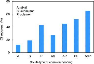
Enhanced oil recovery (EOR) performance of unitary, binary, and ternary chemical flooding was estimated based on experiments and the results are listed in Table 2 (core numbers 4 to 10). Experimental outcome documents that ternary chemical flooding (ASP) achieved the highest oil recovery compared with unitary and binary cases. This is due to the contribution of a synergistic effect within the alkali–surfactant–polymer. Nevertheless, alkali–polymer (AP) flooding only has a slight oil recovery increment compared with that of polymer flooding. This implies that not all chemical agents will have synergistic effects at all times and the synergistic effects between chemical agents are conditional. Considering the complexity of interactions within an alkali–surfactant–polymer, the synergistic mechanism of ASP flooding still needs further investigation (Fig. 1).3.2. Characteristic study of ASP flooding
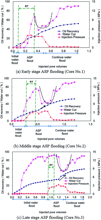
Different initial water flood slug sizes represent different development stages after which an ASP solution is injected into a core (core numbers 1, 2, and 3 as shown in Table 2). For core number 1, ASP flooding was conducted in an early stage of the development when water cut was low. As shown in Fig. 2(a), water cut increased rapidly to 66% and then dropped significantly after it achieved a critical point, which indicated that ASP flooding was effective. After that, water cut was reversed to increase slowly during the later period of ASP flooding and the continued water flooding period. The U-shape (as black dashed line shown in Fig. 2(a)) of a water cut curve during this period is a clear response characteristic of ASP flooding. Another important observation is that injection pressure is shown as a trapezoid and a high injection pressure stair during an ASP flooding period. The experimental results of corefloods 2 and 3 with ASP flooding conducted at middle and late stages of development are shown in Fig. 2(b) and (c), respectively. Water cut reverse and U shape of a water cut curve also can be observed from these two figures. The performance of injection pressure is similar to that observed in Fig. 2(a). It is also important to note that oil recovery increase accelerates gradually as a result of ASP solution injection (marked by black arrows in Fig. 2(b) and (c)). Additionally, the response time (RT), which is the interval between ASP flooding start time and water cut critical time, shortens with the delay of ASP flooding (compare Fig. 2(a)–(c)). This indicates that quick response and effectiveness can be obtained for late stage ASP flooding.4. Synergistic mechanism investigation of ASP flooding
Generally, inhibitory and synergist actions within chemical agents will occur at the same time for multi-component chemical flooding. These interactions will affect the properties of a multi-component solution and then master the performance of chemical flooding. Hence, the interactions of an alkali–surfactant–polymer on viscosity, interfacial tension, and adsorption were studied with laboratory experiments.4.1. Viscosity sensitivity analysis of ASP solution
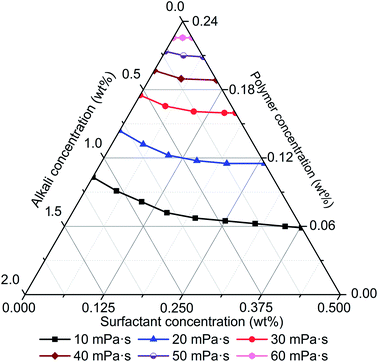
The effects of alkali, surfactant, and polymer on viscosity of ASP solution were studied based on rheology experiments and the results are shown in Fig. 3. Alkali, surfactant, and polymer affect the viscosity of an ASP solution at same time, but the sensitivity of each chemical agent is different according to its ternary phase diagram as shown in Fig. 3. As viscosity contour lines show, viscosity increases step by step with increasing polymer concentration and crosslinking probability of polyacrylamide molecules grows exponentially with increasing polymer concentration. This leads to a non-linear variation of ASP solution viscosity and performs as the viscosity increase gradually accelerates. It is also important to note that the effect of polymer on viscosity is more significant compared with that of alkali and surfactant, which indicates that polymer is the primary control factor of ASP solution viscosity.As shown in Fig. 3, the decline of ASP solution viscosity with increase of alkali concentration is significant, and implies that alkali limits the contribution of polymer to viscosity. Polyacrylamide molecular stretches exist without alkali as a repulsive force. Alkali provides cations which can reduce the repulsive force within polyacrylamide molecules based on a charge shielding mechanism. Then, polyacrylamide molecules shrink rather than stretch, which leads to a decline of molecular hydraulic radius. Additionally, crosslinking probability of polyacrylamide molecules decreases with the reduction of molecular hydraulic radius. Finally, the viscosity of an ASP solution diminishes with an increase of alkali concentration. It is also important to note that a minor reduction of viscosity can be found with an increase of surfactant concentration. This indicates that a surfactant has slight influence on viscosity. Consequently, ASP solution viscosity is determined primarily by polymer and secondary by alkali, and the effect of a surfactant is relatively small.
4.2. Interfacial tension sensitivity analysis of ASP solution
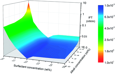
Interfacial tension (IFT), at the petroleum–aqueous phase interface, is one of the key parameters to determine ASP flooding effectiveness. Generally, the lower the IFT, the easier an oil–water mixture occurs, hence, ultra-low IFT usually is expected for ASP flooding. The effect of polymer on IFT is insignificant when crude oil mixes with ASP solution in a vessel. But, if an ASP solution is injected into a core which is saturated with crude oil, then a polymer can reduce surfactant adsorption on the mineral surface by an alternative mechanism during the flooding process. Then, oil–water IFT will decline indirectly due to an increasing active-surfactant concentration.Fig. 4 shows oil–water IFT as a function of surfactant and alkali concentrations. A sharp decrease can be seen after alkali joins in and the trend flattens out quickly with an increase of alkali concentration. When oil and aqueous phases come in contact, in situ petroleum acid HP in the oil phase and NaOH in the aqueous phase will migrate to the interface, react, and produce petroleum soap (NaP) which is a kind of in situ surfactant. With an increase of NaOH concentration, more petroleum soaps are produced and the density of P− at the interface increases, which leads to the dropping of IFT. But limited by the content of petroleum acid in crude oil, more NaOH won't contribute to IFT reduction anymore after petroleum acid is completely converted. Hence, an IFT surface turns into a platform after a critical alkali concentration is achieved.
It is obvious that the effect of surfactant on IFT is more significant than that of alkali. The addition of surfactant into a petroleum–alkali–polymer system can influence oil–water IFT behavior and oil recovery in two ways. On one hand, the surfactant may adsorb at the oil–water interface to improve interfacial properties and then enhance the oil–water mixture. On the other hand, the surfactant may form mixed micelles with petroleum soap NaP which is produced by an alkali and petroleum acid chemical reaction, and then perform a synergetic action between surfactant and alkali. Another important observation is that IFT decreases rapidly when surfactant concentration is low, but it turns to increasing after surfactant concentration achieves 0.2 wt% (see Fig. 4). Diffusion equilibrium may be the reason for IFT turning to increasing from decreasing with the variation of surfactant concentration. Part of the surfactant may dissolve in the oleic phase rather than aqueous phase and won't contribute to IFT reduction anymore when surfactant concentration achieves critical value. Meanwhile, emulsification also can lead to the IFT increase.
It should be mentioned that all the analysis discussed above is based on laboratory experiments conducted in a vessel. Moreover, an oilfield pilot is still necessary to ensure that the synergistic mechanism of alkali–surfactant–polymer on viscosity can indeed be achieved in situ when the ASP solution contacts with crude oil in a porous media during the flooding process.
4.3. Adsorption investigation of ASP flooding
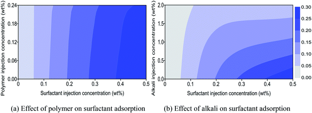
Physical reactions between chemical agents with sandstone mineral also will affect the performance of ASP flooding. Adsorption, entrapment, retention, and trapping are the main reasons that lead to the loss of chemical agents, and adsorption is the leading cause for chemical consumption.30–32 Chemical adsorption behavior and the effects on the synergistic mechanism of ASP flooding were determined through coreflood experiments.In Fig. 5(a), the abscissa and ordinate are surfactant and polymer concentrations of a surfactant–polymer (SP) solution injected into a core. The concentration of surfactant which adsorbed on mineral surface of the core can be obtained by detecting effluent surfactant concentration after SP flooding. Surfactant adsorption concentration scatter data were measured by experiments with core numbers 11 to 30 listed in Table 3. Then a surfactant adsorption concentration contour plot was drawn based on obtained scatter data, and the result is shown in Fig. 5(a). It can be observed that surfactant adsorption concentration increases with increasing surfactant injection concentration when polymer injection concentration is constant. The interval between two adjacent contours enlarges with increasing surfactant injection concentration, which denotes that the increasing speed of surfactant adsorption concentration will gradually slow down. This implies that surfactant adsorption will tend to a dynamic plateau with mounting surfactant injection concentration. It also can be observed that surfactant adsorption concentration diminishes slightly with increasing polymer injection concentration for the same surfactant injection concentration. A polymer has a disadvantage on competitive adsorption compared with surfactant. As a result, it has a slight effect on surfactant adsorption under low concentration. Nevertheless, the viscosity of a SP solution will increase with increasing polymer concentration. Rheology improvement of a SP solution will decline surfactant diffusion rate in a core.33 Then surfactant adsorption concentration has a significant decrease under high surfactant and polymer concentrations.
Fig. 5(b) shows a surfactant adsorption concentration contour plot of alkali–surfactant (AS) flooding based on experimental results from core numbers 31 to 50 listed in Table 3. It can be observed that the effect of alkali on surfactant adsorption is more significant compared with that of polymer (see Fig. 5(a) and (b)). First, alkali is usually a sacrificial agent to replace surfactant from adsorbing on a mineral surface to keep chemical adsorption equilibrium. Also, it can protect a surfactant from adsorption consumption and enhance its contribution to IFT reduction. This is an alternative mechanism between alkali and surfactant. Second, alkali will increase AS solution's pH and lead a negatively charged mineral surface to become more electro-negative. Then, the repulsion force between mineral surface and anionic surfactant is enhanced which reduces the proportion of surfactant to be adsorbed directly on mineral surface. Third, crude oil usually contains petroleum acid which can react with alkali to produce a water-soluble surfactant. This produced petroleum surfactant will occupy adsorption positions of injected surfactant on a mineral's surface, and then reduce its adsorption loss.34 Hence, dramatic reduction of surfactant adsorption concentration can be seen in the presence of alkali, and the reduction decelerates gradually with increasing alkali injection concentration (see Fig. 5(b)). Surfactant adsorption concentration will convert from an abrupt drop to a smooth decline when alkali injection concentration rises to a certain degree. This indicates that more alkali will have less contribution to surfactant adsorption reduction when adsorption capacity of the mineral is approached or achieved. Additionally, the alternative mechanism of a surfactant with alkali is usually used to reduce the dosage of surfactant and enhance oil recovery in oilfield applications, which ensures better economic performance of ASP flooding as a surfactant is usually more expensive than alkali.
5. Numerical simulation development of synergistic mechanism
In this part, numerical simulation methods were developed to characterize the ASP flooding synergistic mechanism which had been obtained from experiments. Simulations of viscosity mixing, IFT reduction, and multicomponent adsorption were studied separately.5.1. Viscosity non-linear logarithm mixing calculation
In formula (1) of a traditional linear logarithm mixing rule, mass fraction wi acts as a weight factor during multi-component viscosity mixing calculations.35
 | (1) |
The viscosity mixing calculation of ASP solution in this study can be converted as:
ln![[thin space (1/6-em)]](https://www.rsc.org/images/entities/char_2009.gif) μ = wA μ = wA![[thin space (1/6-em)]](https://www.rsc.org/images/entities/char_2009.gif) ln ln![[thin space (1/6-em)]](https://www.rsc.org/images/entities/char_2009.gif) μA + wS μA + wS![[thin space (1/6-em)]](https://www.rsc.org/images/entities/char_2009.gif) ln ln![[thin space (1/6-em)]](https://www.rsc.org/images/entities/char_2009.gif) μS + wP μS + wP![[thin space (1/6-em)]](https://www.rsc.org/images/entities/char_2009.gif) ln ln![[thin space (1/6-em)]](https://www.rsc.org/images/entities/char_2009.gif) μP μP
| (2) |
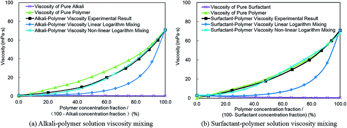
Based on the linear logarithm mixing method shown in formula (2), the viscosity of an alkali–polymer solution can be calculated (see Fig. 6(a)). It can be observed that the calculated viscosity by the linear logarithm mixing method doesn't match as well with the experimental results. A similar phenomenon also can be observed from the comparison of the surfactant–polymer solution viscosity mixing result with experimental data (see Fig. 6(b)). This denotes that the viscosity linear logarithm mixing method, which doesn't consider interactions within alkali, surfactant, and polymer, is neither comprehensive nor complete. To solve this problem, a multivariate regression analysis was conducted according to the consequence of experiments we had already obtained (as shown in Fig. 3). The regression result, which is a new multi-component viscosity non-linear logarithm mixing rule, is put forward in formula (3). The effects of alkali and surfactant on the viscosity of polymer are considered by an exponential term which involved alkali and surfactant concentrations. The corresponding affect factors can be measured and matched based on the experimental results in part 4.1 of this paper.
Consider formula (3):
ln![[thin space (1/6-em)]](https://www.rsc.org/images/entities/char_2009.gif) μ = wA μ = wA![[thin space (1/6-em)]](https://www.rsc.org/images/entities/char_2009.gif) ln ln![[thin space (1/6-em)]](https://www.rsc.org/images/entities/char_2009.gif) μA + wS μA + wS![[thin space (1/6-em)]](https://www.rsc.org/images/entities/char_2009.gif) ln ln![[thin space (1/6-em)]](https://www.rsc.org/images/entities/char_2009.gif) μS + c × e(cAwA+cSwS) × wP μS + c × e(cAwA+cSwS) × wP![[thin space (1/6-em)]](https://www.rsc.org/images/entities/char_2009.gif) ln ln![[thin space (1/6-em)]](https://www.rsc.org/images/entities/char_2009.gif) μP μP
| (3) |
The normalized summation of alkali and polymer (Fig. 6(a)) or surfactant and polymer (Fig. 6(b)) mass fractions as 100%, and the viscosity non-linear logarithm mixing result is shown in Fig. 6. The outcome documents that the viscosity calculation result based on non-linear logarithm mixing method matches very well with experiment results compared with that of the linear logarithm mixing method. Hence, the non-linear logarithm mixing method was employed to replace the traditional linear logarithm mixing method to conduct the multi-component viscosity mixing calculation in ASP flooding numerical simulations.
5.2. IFT reduction–relative permeability curve interpolation
During ASP flooding process, oil–water phases IFT reduction with the join in of chemical agent usually reflects on the variation of capillary number and relative permeability curve. Formula (4) is usually employed to describe the relationship of capillary number with IFT:
 | (4) |
IFT will be affected by surfactant and alkali at the same time according to the experimental results discussed before. As shown in formula (4), capillary number is the function of surfactant only, which is inaccurate because the effect of alkali is ignored. Then, a formula which considers the effects of surfactant and alkali on IFT at the same time can be improved as:
 | (5) |
| jA = j0 + a × ewA/b | (6) |
IFT changes with the variation of surfactant and alkali concentrations, then the corresponding capillary number can be calculated by formula (5). Improved water phase relative permeability for different surfactant and alkali combinations can be calculated according to the interpolation method shown in formula (7).36 The oil phase relative permeability curve interpolation method is similar to that of the water phase:
 | (7) |
| dh = lg(NcH.IFT) | (8) |
| dl = lg(NcU.L.IFT) | (9) |
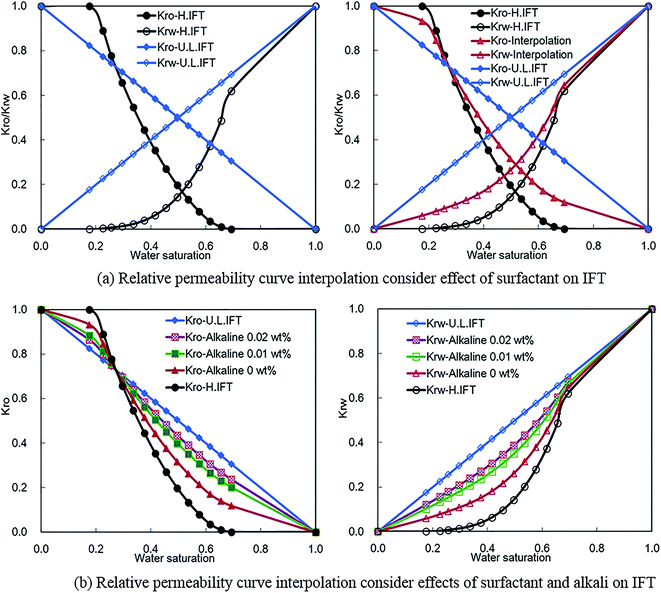
Oil–water phase IFT is high for water flooding without alkali, surfactant, and polymer. The corresponding oil and water phase relative permeability curves are shown by Kro-H.IFT and Krw-H.IFT separately in Fig. 7. IFT will reduce to an ultra-low level, and oil can mix with water completely when surfactant (or surfactant and alkali) reach to a critical concentration. Then, oil and water phase relative permeability curves will convert to straight lines (see Kro-U.L.IFT and Krw-U.L.IFT in Fig. 7). According to a traditional interpolation method, the relative permeability curve for actual ASP flooding can be interpolated based on the two sets of original relative permeability curves shown in left chart of Fig. 7(a). The interpolation results of Kro-interpolation and Krw-interpolation can be observed in Fig. 7(a) (corresponding surfactant concentration is 0.1 wt%). It should be mentioned that the interpolated relative permeability curve only varies with surfactant concentration. So, it can't characterize the synergistic effects of surfactant and alkali on IFT reduction for ASP flooding.
For different alkali concentration conditions (surfactant concentration is fixed as 0.1 wt%), corresponding oil and water phase relative permeability curves can be interpolated based on the improved interpolation method, and the results are shown in Fig. 7(b). The interpolated relative permeability curves describe the effects of surfactant and alkali on oil–water phase filtration behavior. It can be observed that oil and water phase relative permeability capacities increase significantly with the join in of surfactant (Kro-H.IFT to Kro-Alkali 0 wt% and Krw-H.IFT to Krw-Alkali 0 wt%). The effect of alkali on relative permeability decreases gradually with the increase of alkali concentration. It is interesting to note that the effect of surfactant on relative permeability improvement is dominant compared with that of alkali. These phenomena are in good agreement with experimental results shown in Fig. 4. This implies that the improved relative permeability curve interpolation method is more appropriate for ASP flooding.
5.3. Multicomponent adsorption characterization
Generally, adsorptions of alkali and polymer usually obey a Langmuir adsorption isotherm. By contrast, surfactant adsorption is affected by alkali and polymer at the same time according to experimental results shown in Fig. 5. So, surfactant adsorption can't be characterized by a Langmuir adsorption isotherm model anymore. The effect of polymer on surfactant adsorption is slight enough compared with that of alkali that we neglected it in this study. Hence, surfactant adsorption analysis can be simplified into surfactant and alkali double factors. Multivariate regression was conducted based on the experimental result shown in Fig. 5(b). A multicomponent adsorption isotherm model which considers the effects of alkali and surfactant at the same time was constructed and the corresponding formulas are shown as follows:| Sad = g + h × eEA + m × eES + n × eEA+ES | (10) |
 | (11) |
 | (12) |
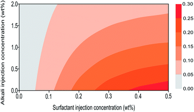
This multicomponent adsorption isotherm model can be used to characterize surfactant adsorption phenomenon under alkali–surfactant–polymer multicomponent adsorption condition during an ASP flooding process. Fig. 8 shows surfactant adsorption contour lines which are plotted based on the proposed model. It can be observed that the differences between proposed model simulation result (Fig. 8) and experimental results (Fig. 5(b)) are insignificant. This validates that the accuracy of our proposed model is acceptable so now it can be used to conduct multicomponent adsorption numerical simulations.
6. Numerical simulation model construction and validation
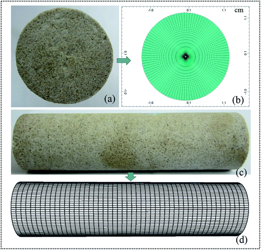
A static simulation core (as shown in Fig. 9(b) and (d)) which has the same properties as our experimental core was established (see Fig. 9(a) and (c); the details are listed in Table 2). A total of 2100 grids were designed for each cross section (see Fig. 9(a) and (b)). Fig. 9(c) and (d) show the experiment core and corresponding simulation core from a longitudinal view. A cylindrical grid system was employed to simulate plane radial flow in the core during a flooding process. It can be observed that the simulation core was divided into 50 segments lengthways. There is a total of 105![[thin space (1/6-em)]](https://www.rsc.org/images/entities/char_2009.gif) 000 (21 × 100 × 50) grids in the simulation core after meshing. Based on an established simulation core, a novel ASP flooding numerical simulation model was constructed, which integrated the created viscosity non-linear logarithm mixing method, IFT reduction–relative permeability curve interpolation method, and multicomponent adsorption isotherm model. To validate the effectiveness of this proposed novel numerical simulation model, experiments with core numbers 1, 2, and 3 (as shown in Table 2) were repeated using this numerical simulation.
000 (21 × 100 × 50) grids in the simulation core after meshing. Based on an established simulation core, a novel ASP flooding numerical simulation model was constructed, which integrated the created viscosity non-linear logarithm mixing method, IFT reduction–relative permeability curve interpolation method, and multicomponent adsorption isotherm model. To validate the effectiveness of this proposed novel numerical simulation model, experiments with core numbers 1, 2, and 3 (as shown in Table 2) were repeated using this numerical simulation.
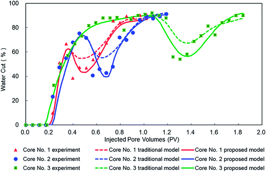
Numerical simulation results based on our proposed model and a traditional model are shown in Fig. 10, and the corresponding experimental results collected from Fig. 2 also were supplied for comparison. It can be observed that all water cut curves in Fig. 10 show a U-shape during ASP flooding process, which validates the analysis results of the characteristic study. Compared with a traditional model, water cut simulated by our proposed model declines more significantly and also is much closer to experimental results for early, middle, and late stages of ASP flooding. This indicates that our proposed model accurately can characterize filtration behavior of ASP flooding. This is due to the proposed model being developed using the numerical simulation methods of viscosity mixing, IFT reduction, and multicomponent adsorption, and then enhancing the characterization of synergistic effects within an alkali–surfactant–polymer during ASP flooding process. In brief, comparing results validated the effectiveness and advantage of our proposed model for ASP flooding simulations.
Furthermore, our proposed model can be used to enhance the study of ASP flooding because it can overcome the problem with experiments in which it is impossible to measure all parameters exactly. On one hand, it can be used to study filtration behavior in a core and cooperate with lab experiments to reveal an unknown mechanism of ASP flooding. On the other hand, it can also expand to an oilfield scale to conduct development optimization and production prediction, and then enhance an ASP flooding filed application.
7. Conclusions
(1) EOR capacity of ternary chemical flooding is better than that of unitary and binary due to alkali–surfactant–polymer synergistic effects. Water cut reverse, high injection pressure, and U shape of a water cut curve are response characteristics of ASP flooding.(2) ASP solution viscosity presents non-linear variation behavior due to polymer molecules crosslinking probability growing exponentially. Alkali will diminish the molecular hydraulic radius of polyacrylamide and then limit its contribution to viscosity. A novel viscosity non-linear logarithm mixing simulation method was created to couple the multiple effects of alkali–surfactant–polymer on viscosity.
(3) Diffusion equilibrium, reverse dissolution, and emulsification of surfactant will affect IFT reduction performance. Alkali can perform a synergetic action with surfactant on IFT reduction by producing in situ petroleum soaps. An improved relative permeability curve interpolation method which considers the effects of surfactant and alkali on IFT was developed to characterize their influences on filtration behavior.
(4) ASP solution rheology improvement caused by polymer will restrain diffusion rate of a surfactant and then diminish its adsorption. Alkali can protect a surfactant from adsorption by pH improvement and an alternative mechanism. A multicomponent adsorption isotherm model was established to simulate adsorption behavior in an alkali–surfactant–polymer multicomponent environment.
(5) A novel ASP flooding numerical simulation model was constructed which coupled developed synergistic mechanism characterization methods of viscosity non-linear logarithm mixing, relative permeability curve interpolation, and multicomponent adsorption. Comparison results validated the effectiveness of this novel model, and it can be used to enhance mechanism studies and field applications of ASP flooding.
Nomenclature
| ASP | Alkali–surfactant–polymer |
| IFT | Interfacial tension |
| mD | 10−3 μm2 |
| wt% | Weight percent |
| PV | Pore volume |
| MPa | 106 Pa |
Conflicts of interest
There are no conflicts to declare.Acknowledgements
The authors would like to acknowledge China University of Petroleum for allowing us to present this article. This work was financially supported by Shandong Provincial Natural Science Foundation, China (Grant No. ZR2017BEE044), the Foundation of State Key Laboratory of Petroleum Resources and Prospecting, China University of Petroleum, Beijing (Grant No. PRP/open-1707), National Science and Technology Major Project (Grant No. 2016ZX05011-001) and Scientific Research Foundation of China University of Petroleum (East China) (Grant No. 2014010607). We also appreciate Ester Brighton Mkamba for her English language support.References
- F. F. J. Lin, G. J. Besserer and M. J. Pitts, J. Can. Pet. Technol., 1987, 6, 54–65 Search PubMed.
- J. J. Sheng, Asia-Pac. J. Chem. Eng., 2014, 9, 471–489 Search PubMed.
- K. M. Ko, B. H. Chon, S. B. Jang and H. Y. Jang, J. Ind. Eng. Chem., 2014, 20, 228–233 CrossRef.
- M. Sedaghat, O. Mohammadzadeh, S. Kord and I. Chatzis, Can. J. Chem. Eng., 2016, 94, 779–791 CrossRef.
- B. Huang, W. Zhang, R. Xu, Z. Shi, C. Fu, Y. Wang and K. Song, Energies, 2017, 10, 951 CrossRef.
- Y. Ma, J. Hou, F. Zhao and Z. Song, RSC Adv., 2018, 8, 8269–8284 RSC.
- H. A. Nasr-EI-Din, B. F. Hawkins and K. A. Green, J. Pet. Sci. Eng., 1992, 6, 381–401 CrossRef.
- Z. Tong, C. Yang, G. Wu, H. Yuan, L. Yu and G. Tian, SPE/DOE Improved Oil Recovery Symposium, Tulsa, Oklahoma, 1998, SPE 39662 Search PubMed.
- W. Pu, C. Yuan, W. Hu, T. Tan, J. Hui, S. Zhao, S. Wang and Y. Tang, RSC Adv., 2016, 6, 50640–50649 RSC.
- M. Nedjhiouia, N. Moulai-Mostefa, A. Morslia and A. Bensmailib, Desalination, 2005, 185, 543–550 CrossRef.
- T. Guo, Y. Li, Y. Ding, Z. Qu, N. Gai and Z. Rui, Energy Fuels, 2017, 31, 10479–10489 CrossRef.
- W. Pu, R. Liu, B. Li, F. Jin, Q. Peng, L. Sun, D. Du and F. Yao, RSC Adv., 2015, 5, 88002–88013 RSC.
- H. Gong, H. Zhang, L. Xu, K. Li, L. Yu, Y. Li and M. Dong, RSC Adv., 2017, 7, 39564–39575 RSC.
- Z. Liu, X. Yue, J. Hou and L. Zhang, SPE Asia Pacific Oil and Gas Conference and Exhibition, Melbourne, Australia, 2002, SPE 77876 Search PubMed.
- P. Shen, J. Wang, S. Yuan, T. Zhong and X. Jia, SPE J., 2009, 237–244 CrossRef.
- J. Hou, Z. Liu, S. Zhang, X. Yue and J. Yang, J. Pet. Sci. Eng., 2005, 47, 219–235 CrossRef.
- V. Bortolotti, P. Macini and F. Srisuriyachai, SPE Asia Pacific Oil and Gas Conference and Exhibition, Jakarta, Indonesia, 2009, SPE 122499 Search PubMed.
- D. B. Levitt, S. Dufour, G. Pope, D. Morel and P. Gauer, International Petroleum Technology Conference, Bangkok, Thailand, 2012, IPTC 14915 Search PubMed.
- H. Mohammadi, M. Delshad and G. A. Pope, SPE Reservoir Eval. Eng., 2009, 518–527 CrossRef.
- L. E. Zerpa, N. V. Queipo and J. L. Salager, SPE/DOE Fourteenth Symposium on Improved Oil Recovery, Tulsa, Oklahoma, 2004, SPE 89387 Search PubMed.
- S. Yuan, P. Yang, Z. Dai and K. Shen, International Meeting on Petroleum Engineering, Beijing, PR China, 1995, SPE 29904 Search PubMed.
- R. Moreno, L. Anselmi, D. Coombe, C. Card and I. Cols, Petroleum Society's Canadian International Petroleum Conference, Calgary, Alberta, Canada, 2003, SPE 2003–199 Search PubMed.
- S. L. Van and B. H. Chon, J. Ind. Eng. Chem., 2016, 38, 200–210 CrossRef.
- R. Farajzadeh, T. Matsuura, D. van Batenburg, H. Dijk and B. V. Rijswijk, SPE Enhanced Oil Recovery Conference, Kuala Lumpur, Malaysia, 2011, SPE 143671 Search PubMed.
- K. Wyatt, M. J. Pitts and H. Surkalo, SPE Eastern Regional Meeting, Lexington, Kentucky, USA, 2002, SPE 78711 Search PubMed.
- J. Vargo, J. Turner, B. Vergnani, M. J. Pitts, K. Wyatt, H. Surkalo and D. Patterson, SPE Reservoir Eval. Eng., 2000, 3, 552–558 CrossRef.
- H. L. Chang, Z. Q. Zhang, Q. M. Wang, Z. S. Xu, Z. D. Guo, H. Q. Sun, X. L. Cao and Q. Qiao, JPT, J. Pet. Technol., 2006, 58, 84–89 CrossRef.
- D. Wang, J. Cheng, J. Wu, Z. Yang, Y. Yao and H. Li, SPE Asia Pacific Improved Oil Recovery Conference, Kuala Lumpur, Malaysia, 1999, SPE 57288 Search PubMed.
- S. Huang and M. Dong, J. Can. Pet. Technol., 2004, 43, 56–61 CrossRef.
- J. Shen, Y. Bai, Q. Yin, W. Wang, X. Ma and G. Wang, J. Ind. Eng. Chem., 2017, 56, 82–89 CrossRef.
- M. Chahardowli, R. Farajzadeh and H. Bruining, J. Ind. Eng. Chem., 2016, 38, 50–60 CrossRef.
- R. Farajzadeh, A. Ameri, M. J. Faber, D. W. van Batenburg, D. M. Boersma and J. Bruining, Ind. Eng. Chem. Res., 2013, 52, 13839–13848 CrossRef.
- D. Li, M. Shi, D. Wang and Z. Li, SPE International Symposium on Oilfield Chemistry, Woodlands, Texas, USA, 2009, SPE 121598 Search PubMed.
- S. Liu, D. L. Zhang, W. Yan, M. Puerto, G. J. Hirasaki and C. A. Miller, SPE J., 2008, 1–16 Search PubMed.
- D. Camilleri, A. Fil, G. A. Pope, B. A. Rouse and K. Sepehrnoori, SPE Reservoir Eng., 1987, 433–440 CrossRef.
- M. R. Todd, J. K. Dietrich, A. Goldburg and R. G. Larson, The Fifth Symposium on Improved Methods for Oil Recovery, Tulsa, Oklahoma, USA, 1978, SPE 7077 Search PubMed.
| This journal is © The Royal Society of Chemistry 2018 |

