DOI:
10.1039/C8RA03343A
(Paper)
RSC Adv., 2018,
8, 19732-19738
Stability and local magnetic moment of bilayer graphene by intercalation: first principles study
Received
18th April 2018
, Accepted 22nd May 2018
First published on 29th May 2018
Abstract
The migration and magnetic properties of the bilayer graphene with intercalation compounds (BGICs) with magnetic elements are theoretically investigated based on first principles study. Firstly, we find that BGICs with transition metals (Sc–Zn) generate distinct magnetic properties. The intercalation with most of the transition metal atoms (TMAs) gives rise to large magnetic moments from 1.0 to 4.0 μB, which is valuable for the spintronics. Moreover, graphene can protect the intrinsic properties of the intercalated TMAs, which can be important for applications in catalysis. These phenomena can be explained by theory of spd hybridization definitely. Secondly, weak coupling between TMAs and the surroundings indicates the possibility of implementing quantum information processing and generating controlled entanglements. For the possibility of using these materials in ultrafast electronic transistors, spintronics, catalysis, spin qubit and important applications for the extensions of graphene, we believe that BGICs can provide a significant path to synthesize novel materials.
1 Introduction
Since graphene was firstly reported by Novoselov and Geim,1 materials based on graphene have demonstrated a wide range of potential applications due to its unusual electronic properties, spacial twists, topological phases, reduced dimensionality and single-atom thickness scales.2–7 In recent years, graphene has been obtained from graphite fluoride,8 oxidized graphite,9–11 hydrogenated graphite12,13 and polymerization of aniline inside the expanded graphite14 using the intercalation method. Elements containing d or f electrons show strong interaction with carbon, making it possible to bring distinct electronic and magnetic properties to graphene in low-dimensional systems when these elements are intercalated in or doped to graphene.15–24 Thus, the modified graphene can be used as the next-generation electronic devices, such as recording media, magnetic inks, spin qubits and spintronic devices.25–27 However, despite its intriguing properties, some of the biggest hurdles for graphene to be used as an electronic material are the lack of an energy gap in its electronic spectra and the absence of magnetic moment in its intrinsic structure. Thus, an opening sizeable and well-defined band gap should be designed in a graphene-based transistor.28 Moreover, recent works indicate that van der Waals heterostructures based on graphene and 2D crystals are potential for catalytic applications,29 in which graphene can protect the intrinsic properties of catalytic atoms and enhance the interactions by constructing confinement environment.
The graphite intercalation compounds (GICs) have been exhibiting some exotic phenomena such as superconductivity.30 Due to its medium electronegativity, carbon acts as an amphoteric element, so that graphite can provide or accept electrons in intercalation reactions. A lot of elements can intercalate into graphite producing compounds, including H, O, halogens, alkali metals,31–34 alkaline-earth metals,35 several lanthanides such as Gd, Eu, Yb, and transition metal atoms (TMAs) such as Pt, Pd, Ru, etc.36–38 These intercalation can be realized in bilayer or multi-layer graphene because of the same sp2 hybridization and van der Waals interactions as in graphite,15,39–41 furthermore, graphene can exhibit more special properties and applications. Experiments have shown the charge-density wave and some hints of superconductivity in Ca-intercalated bilayer graphene.42,43 Therefore, TMA-intercalated bilayer graphene is expected to exhibit exotic properties.
In this work, the electronic and magnetic structures of bilayer graphene with intercalation compounds (BGICs) using TMAs are investigated using first principles calculations based on density functional theory (DFT). The intercalation of most of TMAs (Sc–Zn) induces large magnetic moments into the systems. The density of states (DOS) shows the formation of sp3 hybridization of carbon atoms and the spd hybridized orbitals of TMAs, giving rise to the peculiar electronic and magnetic properties of the BGICs. The further analysis of spin-polarization shows that the weak coupling between the TMAs and the surroundings, which is a prerequisite for implementing quantum information processing and generating controlled entanglement. The stable TMAs compounds can also be potential in catalyst.
2 Computational details
We perform spin-polarized DFT44 calculations as implemented in Quantum-ESPRESSO package.45 We use Vanderbilt ultra-soft pseudopotentials46 for core electrons and the generalized gradient approximation (GGA) of PBE47 for exchange-correlation functional. A plane-wave basis setup to a kinetic energy cutoff of 45 Ry for the wavefunction and of 450 Ry for the charge density are used in all simulations. The Brillouin zone is sampled using a 6 × 6 × 2 Monkhorst–Pack grid48 with Methfessel–Paxton49 smearing of 0.01 Ry. Increasing the energy cutoff up to 55 Ry and 12 × 12 × 4 k-point sampling show the convergent results. GGA+U calculations for TMAs are performed using U from 2 to 5 eV.50 A 15 × 15 × 15 Monkhorst–Pack grid is used for the calculation of band structures and DOS. Atomic positions are optimized until the maximum force on any atom is less than 0.001 a.u. The similar approach has been successfully applied to simulate the electronic properties of graphite and bilayer graphene.51–55 The semi-empirical force-field correction method named DFT-D2 scheme56,57 is used to treat the van der Waals interactions of two layers of graphene. Since GGA+DFT-D2 can calculate the correct electronic properties of the bilayer graphene-related materials,58,59 we will discuss in more detail only the GGA data, and fix the interlayer separation at the experimental value 3.35 Å (ref. 60) as the initial configurations for bilayer graphene.
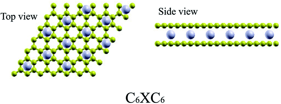
For TMAs intercalation, the configuration of C6XC6 (X represents TMA) is calculated here, including 144 carbon atoms (two layers of 6 × 6 supercells of graphene) and 12 transition metal atoms, similar to configuration of the CaC6 GICs. For comparisons, we also consider only one atom intercalated in the supercell (6 × 6 and 4 × 4 supercells). All these supercell geometries are used with a large separation of 20 Å vacuum. The TMAs located in the center of hexagonal carbons, similar to the configurations of most GICs and TMAs on monolayer graphene.61 For bilayer graphene, both AA and AB stacking bilayer graphene are considered. After carefully comparison, AA stacking of BGICs are more stable, which is also in good agreement with the quantum Monte Carlo calculation of the binding energy of bilayer graphene.62 Therefore, in this article, only the results of AA stacking are shown (Fig. 1).
 |
| | Fig. 1 The stable configurations of C6XC6 (X = TMAs). Carbon atoms are yellow, and TMAs are gray. | |
3 Results and discussion
3.1 Stability of the compounds
We now turn to the TMA intercalation compounds. The atomic structures of all compounds studied in this work are shown in Table 1. We can see that all these configurations are exothermic reactions, indicating the possible synthesis of them. The distances between the two layers of graphene for different TMAs change dramatically. It is noticed that all TMAs considered here except Zn can weakly bond with the hexagonal carbon atoms, making the distance between the two layers of the compounds close to that of pristine bilayer graphene: 3.35 Å (ref. 60). But it is also worthy noting that the distances are generally larger if the radius of the TMAs are larger, such as Sc, Ti. The binding energies are also negative, indicating possible existence and stability. In particular, for Sc, Ti, V, Mn and Co, they are at least as stable as the C6CaC6 BGICs, which is −1.8 eV per TMA according to our calculations using the same model. After the intercalation of TMAs, the lattice constants of the graphene layer change a little, which are from 2.45 to 2.47 Å, comparing with that of the intrinsic graphene: 2.46 Å. Especially for the intercalation of Zn, the lattice constant is 2.46 Å, the same as intrinsic graphene, indicating no binding. This is due to the fact that Zn has a full electronic shell in 3d and 4s orbitals, which indicates that it cannot form bonds with carbon atoms. The bond length of the X–C bond is larger than 2 Å for all compounds, which indicates the weakly binding between the TMAs and carbon atoms.
Table 1 Summary of atomic and magnetic structures of BGICs. The binding energy per TMA Eb (eV per TMA) (defined by the difference between the total energy of the isolated atoms and the total energy of the compounds divided by the number of TMAs), the distance between two layers d (Å), the smallest C–X bond length dB (Å) and the magnetic moments per TMA M (μB per TMA) are shown
| |
Sc |
Ti |
V |
Cr |
Mn |
Fe |
Co |
Ni |
Cu |
Zn |
| 3d14s2 |
3d24s2 |
3d34s2 |
3d54s1 |
3d54s2 |
3d64s2 |
3d74s2 |
3d84s2 |
3d104s1 |
3d104s2 |
| Eb |
−3.785 |
−3.676 |
−3.399 |
−0.932 |
−2.735 |
−0.439 |
−2.260 |
−0.983 |
−0.186 |
−0.102 |
| d |
4.122 |
3.793 |
3.549 |
3.893 |
3.727 |
3.585 |
3.476 |
3.645 |
3.986 |
7.606 |
| dB |
2.501 |
2.367 |
2.270 |
2.429 |
2.344 |
2.286 |
2.247 |
2.312 |
2.449 |
4.075 |
| M |
0.000 |
1.213 |
2.040 |
4.033 |
3.327 |
2.007 |
1.097 |
0.000 |
0.000 |
0.000 |
The stability of the compounds is analyzed by the transition state of the TMAs between different sites using Climbing Image Nudged Elastic Band (CI-NEB) method. As shown in Fig. 2, the barrier of C72CrC72 from site A to B to C is 0.74 eV, indicating the stable trapping chromium atoms in the center of hexagonal carbon. The site B is the top barrier site of the carbon–carbon bond, which indicates an unstable configuration with much higher energy according to Fig. 2(c). However, the barrier of C18FeC18 from site A to B to C shown in Fig. 3(c) is 1.3 eV (increasing the number of carbon atoms giving similar results), and the site B (the bridge site of the carbon–carbon bond) is a metastable configuration with much higher energy according to Fig. 3(c). In Fig. 3, the barrier energy is not symmetric regarding to the center of the image, the reason is that in the NEB calculation, the position of iron is not completely symmetric regarding to the C–C bond. In other words, the moving distance of iron atom in each step is not equal. Such an interesting property indicates a potential application of the BGICs to the information storage and shows that the adatoms can be manipulated if they can get extra energy from an external field. In fact, the barrier of all C18XC18 compounds is larger than 1.0 eV except Zn and Cu, indicating the stability of the compounds.
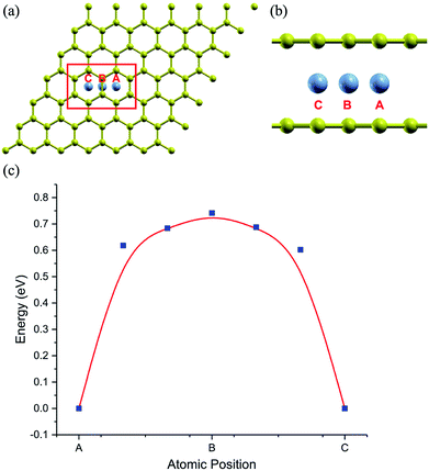 |
| | Fig. 2 The climbing image of C72CrC72. Carbon atoms are yellow, and chromium atoms are gray. (a) and (b) shows the top and partial side view of climbing image with chromium moving from beginning position A, via middle position B, arriving at the final position C, respectively. (c) shows the climbing energy (blue square) of chromium along the moving path. | |
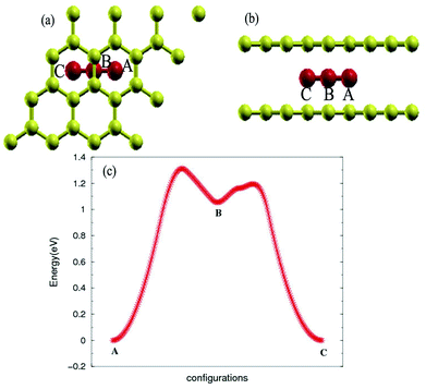 |
| | Fig. 3 Top view (a) and side view (b) of configurations of C18FeC18. (c) Transition state analysis of C18FeC18 from sites A to B to C. Fe atom is red color. | |
3.2 Magnetic properties of the compounds
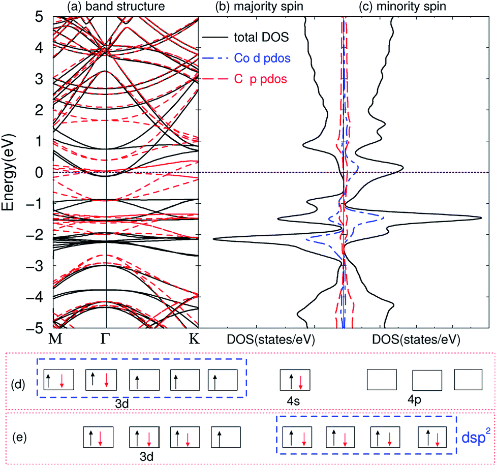
The compounds are magnetic for TMAs from Ti to Co, as shown in Table 1, which are very similar to the magnetic behavior of embedding TMAs in monolayer graphene.63 In order to understand why they exhibit such behaviors, we first calculated the band structures of the compounds. The band structure of C6CoC6 compound is shown in Fig. 4(a). A number of strongly hybridized states of X–C bonding character with small dispersion appear close to the Fermi energy and −2 eV. These states give rise to sharp peaks in the spin-polarized density of states, as shown in Fig. 4(b) and (c). The partial density of states (PDOS) of 3d state of Co and 2p state of C shows that the spin-polarization of the compound mainly comes from the 3d electrons of Co and a little from 2p electrons of C. Besides, some peaks of PDOS of d and s appear in the same positions, such as around −1 eV and −2 eV, which is due to the weak bond of X–C.
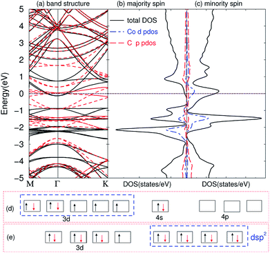 |
| | Fig. 4 Electronic structure of bilayer graphene intercalated Co atoms. (a) Band structure: black solid line represents majority spin, and red dashed line minority spin; (b) DOS of majority spin; (c) DOS of minority spin; (d) the electronic configuration of atomic Co; (e) dsp2 hybridization of the compounds. The Fermi energy is set to zero. | |
By comparing the band structure and DOS of the compounds with those of pristine graphene, and according to the chemical bond theory of coordination compound of the complexes, we use a simple model to qualitatively explain the behaviors in bonding and magnetic properties. Each TMA has 12 nearest carbon atoms (two hexagonal carbon), which is equivalent for the bonding with TMAs. All these carbon atoms weakly bond with the TMAs, and they can form ligand bonds because the TMAs can supply empty orbitals and hexagonal carbon can give π electrons. For Sc, Ti and V atoms, the d electrons are less than five, their properties are similar to the main group elements. Here, we can treat these compounds as XC3 effectively, which means the formation of three covalent bonds. Similar to the M@Au6 (M = Ti, V, Cr) cluster,64 Sc, Ti, and V atoms possess d3, d4 and d5 valence configurations here (i.e., the 4s electrons are promoted to the 3d orbitals). Three of them are involved in the bonding between TMA and carbon atoms, leaving 0, 1 and 2 electrons unpaired respectively. Thus, the magnetic moments are 0, 1 and 2 μB for Sc, Ti and V intercalation respectively. From Cr to Ni, we can explain the magnetic properties using spd hybridization. Taking Co as an example, one can assume that every carbon atom supplies 0.5 e (6 e in total) and Co supplies 3 empty orbitals to form the covalent bond, like CoC6 effectively. As shown in Fig. 4(d), the configuration of atomic cobalt is 3d74s2. After intercalation, the electrons are redistributed. One of the 3d electrons of Co is paired with one electron in other orbital, and then this empty orbital hybridizes with the 4s and 4p orbitals to form dsp2 hybridization. dsp2 hybridization has 4 hybridized orbitals, which can be fully occupied by the 2 electrons of 4s in Co and 6 electrons from C, as shown in Fig. 4(e). Therefore, the compound has only one extra unpaired electron, giving rise to magnetic moment of 1 μB. Similar explanation of dsp2 hybridization can be utilized for Cr, Mn, Fe and Ni, which results in 4, 3, 2, 1 and 0 μB from Cr to Ni, respectively. It is worth noting that hexagonal carbons can supply part of spin-polarization for the compounds, making the magnetic moments not integer. The configurations for Cu and Zn are nonmagnetic, partially because they have full-filled d shells and non-binding with the graphene.
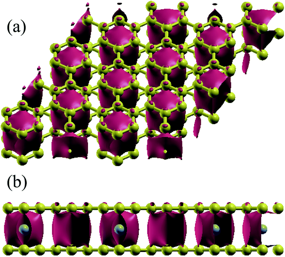
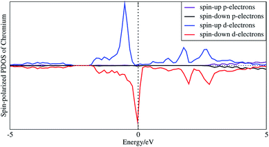
In order to understand the coupling between the interaction of TMAs and two graphene layers, the electronic charge density and spin density distributions for BGICs are shown in Fig. 5 and 6. The spin densities of BGICs are located in TMAs, and the TMAs show the independent atomic behaviors in the BGICs, indicating that they are not involved in the bonding interaction between Cr and graphene layers. This can also be found in the difference charge density as shown in Fig. 6, in which the charge density mainly locates in Cr atoms shown with smaller isosurface of 0.01. The chromium metal, which is the bcc crystal, exhibits antiferromagnetism; however, when a layer of Cr is intercalated in bilayer graphene, the magnetic behavior turns to ferromagnetism. We can see from Fig. 5(c) that the π bond and σ like bond are shown in Cr atoms. It should be noticed that it is spin density plot, which means that the spin polarization of BIGC with Cr atom might be much potential in spintronics. Around the Fermi level, the spin-polarized local density of states (LDOS) of Cr 3p and 3d electrons are completely different, as shown in Fig. 7. It can be found the magnetic moment comes mainly from 3d electrons of Cr atoms.
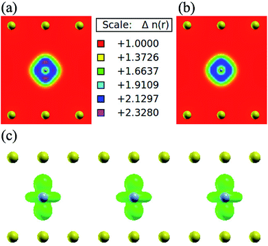 |
| | Fig. 5 Charge density of bilayer graphene intercalated chromium atoms, (a) spin up charge density (two-dimensional view): the different colour represent the different density of electronic distribution according to majority spin; the yellow balls indicate the position of carbon atom while the gray balls representing the Cr atom (in a very small size); (b) spin down charge density: share the same thermometer with (a), but the distribution of electronic density regarding to minority spin. (c) Spin density (isosurface = 0.01 a.u.): the green spheres represent the total spin electronic distribution, which is get by majority spin density mines minority spin density. | |
 |
| | Fig. 6 Electronic difference charge density (defined as the total charge density minuses the charge density of bilayer graphene without TMAs at the same atomic positions) for Cr intercalated in graphene (isosurface = 0.01 a.u.). (a) From top view and (b) front view. | |
 |
| | Fig. 7 Spin-polarized local density of states of 3p and 3d electrons of intercalated chromium atoms. | |
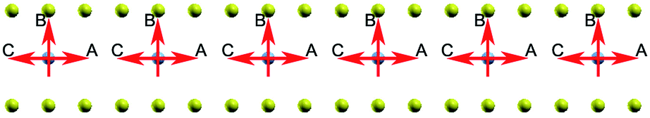
Now we turn to the influence of surroundings (carbon atoms) on the spin polarization. The energy of the system with different direction of spin polarization is investigated. In our calculations the spin polarization of C6XC6 (X = TMAs) is fixed in different directions: perpendicular (B) and parallel (A and C) to graphene layer as shown in Fig. 8. The result illustrates the stable spin direction of chromium atoms is parallel to the graphene layer, which holds the lowest total energy. Both ferromagnetic and anti-ferromagnetic structures are considered. The results show that ferromagnetic state has 0.83 eV lower energy per cell, which indicates that the ferromagnetic state is more stable. It is found that the difference of the energy is less than 0.03 eV for all BGICs with TMAs, which indicates the weak influence of the environment on the local magnetic moments of the TMAs. Specifically, the spin changing energy of the chromium and iron differs in a large scale, as shown in Table 2. It is due to the different magnetic properties of these two atoms: one is anti-ferromagnetic and the other is ferromagnetic, respectively. Cr and Fe have odd (3d54s1) and even (3d64s2) numbers of electrons at the outside of their valence orbits, leaving 6 and 4 unpaired atoms at the valence orbits, respectively. Thus, spin changing of chromium needs more energy according to Pauli exclusion principle. The different spin direction can be used in the information storage, which can be changed and manipulated by external electromagnetic field. This property is a prerequisite for implementing quantum information processing and generating controlled entanglement,65 combining remarkable properties of carbon-based materials,25,66,67 which provides a very promising candidate for solid-state qubit.
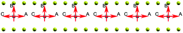 |
| | Fig. 8 The spin of Chromium atoms, the red arrow indicates the spin direction of the chromium atom changes from A to C via B. | |
Table 2 Summary of the energy regarding to the changing spin direction of BGICs
| |
Spin changing energy (eV per atom) |
| C6CrC6 |
0.022 |
| C6FeC6 |
0.008 |
4 Conclusion
We have studied the atomic, electronic and magnetic properties of BGICs using first principle calculations. The TMAs induce high magnetic moments to the compounds, which can be explained by the spd hybridization. Meanwhile, the magnetism is localized, suggesting the other way to experimental realization of Kondo system in graphene except the five possible solutions presented by Sengupta et al.67 Furthermore, the weak coupling of the spin polarization between the TMAs and carbon atoms indicates possibility of application in quantum information. All these properties suggest enormous potential use of these compounds in ultrafast electronic transistors,28 spintronics,68 catalysis and quantum information processing.
Conflicts of interest
There are no conflicts to declare.
Acknowledgements
This work is supported by the National NSFC under Grant No. 11774429 and 11504422, the National Key R&D Program of China under Grant No 2017YFA0403200, the Science Challenge Project under Grant No. TZ2016001, and the Science and Technology Project of Hunan Province under Grant No. 2017RS3038. J. D. thanks the support by the Advanced Research Foundation of National University of Defense Technology under Grant No. JQ14-02-01. Calculations were carried out at the Research Center of Supercomputing Application at NUDT and Supercomputer Center in Lvliang.
References
- K. S. Novoselov, A. K. Geim, S. V. Morozov, D. Jiang, Y. Zhang, S. V. Dubonos, I. V. Grigorieva and A. A. Firsov, Science, 2004, 306, 666–669 CrossRef PubMed.
- S. Carr, D. Massatt, S. Fang, P. Cazeaux, M. Luskin and E. Kaxiras, Phys. Rev. B, 2017, 95, 075420 CrossRef.
- R. Akiyama, Y. Takano, Y. Endo, S. Ichinokura, R. Nakanishi, K. Nomura and S. Hasegawa, Appl. Phys. Lett., 2017, 110, 233106 CrossRef.
- S. Pakhira and J. L. Mendoza-Cortes, J. Phys. Chem. C, 2018, 122, 4768–4782 Search PubMed.
- A. K. Geim and K. S. Novoselov, Nat. Mater., 2007, 6, 183 CrossRef PubMed.
- J. Wu, W. Pisula and K. MÃijllen, Chem. Rev., 2007, 107, 718–747 CrossRef PubMed.
- A. H. Castro Neto, F. Guinea, N. M. R. Peres, K. S. Novoselov and A. K. Geim, Rev. Mod. Phys., 2009, 81, 109–162 CrossRef.
- K. A. Worsley, P. Ramesh, S. K. Mandal, S. Niyogi, M. E. Itkis and R. C. Haddon, Chem. Phys. Lett., 2007, 445, 51–56 CrossRef.
- S. J. Gong, W. Sheng, Z. Q. Yang and J. H. Chu, J. Phys.: Condens. Matter, 2010, 22, 245502 CrossRef PubMed.
- V. C. Tung, M. J. Allen, Y. Yang and R. B. Kaner, Nat. Nanotechnol., 2008, 4, 25 CrossRef PubMed.
- S. Stankovich, D. A. Dikin, G. H. B. Dommett, K. M. Kohlhaas, E. J. Zimney, E. A. Stach, R. D. Piner, S. T. Nguyen and R. S. Ruoff, Nature, 2006, 442, 282 CrossRef PubMed.
- J. O. Sofo, A. S. Chaudhari and G. D. Barber, Phys. Rev. B: Condens. Matter Mater. Phys., 2007, 75, 153401 CrossRef.
- D. C. Elias, R. R. Nair, T. M. G. Mohiuddin, S. V. Morozov, P. Blake, M. P. Halsall, A. C. Ferrari, D. W. Boukhvalov, M. I. Katsnelson, A. K. Geim and K. S. Novoselov, Science, 2009, 323, 610–613 CrossRef PubMed.
- X. Chen, F. Meng, Z. Zhou, X. Tian, L. Shan, S. Zhu, X. Xu, M. Jiang, L. Wang, D. Hui, Y. Wang, J. Lu and J. Gou, Nanoscale, 2014, 6, 8140–8148 RSC.
- F. Huttmann, D. Klar, N. Atodiresei, C. Schmitz-Antoniak, A. Smekhova, A. J. Martínez-Galera, V. Caciuc, G. Bihlmayer, S. Blügel, T. Michely and H. Wende, Phys. Rev. B, 2017, 95, 075427 CrossRef.
- E. J. G. Santos, A. Ayuela and D. SÃąnchez-Portal, New J. Phys., 2010, 12, 053012 CrossRef.
- H. Zhang, J.-T. Sun, H. Yang, L. Li, H. Fu, S. Meng and C. Gu, Carbon, 2016, 107, 268–272 CrossRef.
- Z. Li, W. Xie, X. Liu and Y. Wu, J. Appl. Phys., 2015, 117, 084311 CrossRef.
- X. Liu and Z. Li, J. Phys. Chem. Lett., 2015, 6, 3269–3275 CrossRef.
- F. Donati, Q. Dubout, G. Autès, F. Patthey, F. Calleja, P. Gambardella, O. V. Yazyev and H. Brune, Phys. Rev. Lett., 2013, 111, 236801 CrossRef PubMed.
- N. A. García-Martínez, J. L. Lado, D. Jacob and J. Fernández-Rossier, Phys. Rev. B, 2017, 96, 024403 CrossRef.
- J. Dai, J. Yuan and P. Giannozzi, Appl. Phys. Lett., 2009, 95, 232105 CrossRef.
- J. Dai and J. Yuan, Phys. Rev. B: Condens. Matter Mater. Phys., 2010, 81, 165414 CrossRef.
- S. J. Sung, J. W. Yang, P. R. Lee, J. G. Kim, M. T. Ryu, H. M. Park, G. Lee, C. C. Hwang, K. S. Kim, J. S. Kim and J. W. Chung, Nanoscale, 2014, 6, 3824–3829 RSC.
- B. Trauzettel, D. V. Bulaev, D. Loss and G. Burkard, Nat. Phys., 2007, 3, 192 CrossRef.
- A. Kormányos, V. Zólyomi, N. D. Drummond and G. Burkard, Phys. Rev. X, 2014, 4, 011034 Search PubMed.
- Y. Ge, J. Ji, Z. Shen, Q. Zhang, A. Jian, Q. Duan, C. Wang, J. Jiang, W. Zhang and S. Sang, Carbon, 2018, 127, 432–436 CrossRef.
- F. Schwierz, Nat. Nanotechnol., 2010, 5, 487 CrossRef PubMed.
- D. Deng, K. S. Novoselov, Q. Fu, N. Zheng, Z. Tian and X. Bao, Nat. Nanotechnol., 2016, 11, 218 CrossRef PubMed.
- M. Dresselhaus and G. Dresselhaus, Adv. Phys., 1981, 30, 139–326 CrossRef.
- Y. Yamada, K. Usui, C. H. Chiang, K. Kikuchi, K. Furukawa and A. Yamada, ACS Appl. Mater. Interfaces, 2014, 6, 10892–10899 Search PubMed.
- Y. Guo, R. B. Smith, Z. Yu, D. K. Efetov, J. Wang, P. Kim, M. Z. Bazant and L. E. Brus, J. Phys. Chem. Lett., 2016, 7, 2151–2156 CrossRef PubMed.
- L. Seidl, N. Bucher, E. Chu, S. Hartung, S. Martens, O. Schneider and U. Stimming, Energy Environ. Sci., 2017, 10, 1631–1642 Search PubMed.
- S. Yang, S. Li, S. Tang, D. Shen, W. Dong and W. Sun, Surf. Sci., 2017, 658, 31–37 CrossRef.
- K. Otto and M. Shelef, Carbon, 1977, 15, 317–325 CrossRef.
- N. Emery, C. HÃľrold, J.-F. MarÃłchÃľ and P. Lagrange, Sci. Technol. Adv. Mater., 2008, 9, 044102 CrossRef PubMed.
- X. Zhang, Z. Bao, X. Ye, W. Xu, Q. Wang and Y. Liu, Nanoscale, 2017, 9, 11231–11238 RSC.
- X. Zhang, X. Zhao and Y. Liu, J. Phys. Chem. C, 2016, 120, 22710–22717 Search PubMed.
- A. Grüneis, C. Attaccalite, A. Rubio, D. V. Vyalikh, S. L. Molodtsov, J. Fink, R. Follath, W. Eberhardt, B. Büchner and T. Pichler, Phys. Rev. B: Condens. Matter Mater. Phys., 2009, 79, 205106 CrossRef.
- F. Donati, Q. Dubout, G. Autès, F. Patthey, F. Calleja, P. Gambardella, O. V. Yazyev and H. Brune, Phys. Rev. Lett., 2013, 111, 236801 CrossRef PubMed.
- R. Decker, J. Brede, N. Atodiresei, V. Caciuc, S. Blügel and R. Wiesendanger, Phys. Rev. B: Condens. Matter Mater. Phys., 2013, 87, 041403 CrossRef.
- R. Shimizu, K. Sugawara, K. Kanetani, K. Iwaya, T. Sato, T. Takahashi and T. Hitosugi, Phys. Rev. Lett., 2015, 114, 146103 CrossRef PubMed.
- K. Li, X. Feng, W. Zhang, Y. Ou, L. Chen, K. He, L.-L. Wang, L. Guo, G. Liu, Q.-K. Xue and X. Ma, Appl. Phys. Lett., 2013, 103, 062601 CrossRef.
- P. Hohenberg and W. Kohn, Phys. Rev., 1964, 136, B864–B871 CrossRef.
- P. Giannozzi, S. Baroni, N. Bonini, M. Calandra, R. Car, C. Cavazzoni, D. Ceresoli, G. L. Chiarotti, M. Cococcioni, I. Dabo, A. D. Corso, S. de Gironcoli, S. Fabris, G. Fratesi, R. Gebauer, U. Gerstmann, C. Gougoussis, A. Kokalj, M. Lazzeri, L. Martin-Samos, N. Marzari, F. Mauri, R. Mazzarello, S. Paolini, A. Pasquarello, L. Paulatto, C. Sbraccia, S. Scandolo, G. Sclauzero, A. P. Seitsonen, A. Smogunov, P. Umari and R. M. Wentzcovitch, J. Phys.: Condens. Matter, 2009, 21, 395502 CrossRef PubMed.
- D. Vanderbilt, Phys. Rev. B: Condens. Matter Mater. Phys., 1990, 41, 7892–7895 CrossRef.
- J. P. Perdew, K. Burke and M. Ernzerhof, Phys. Rev. Lett., 1996, 77, 3865–3868 CrossRef PubMed.
- H. J. Monkhorst and J. D. Pack, Phys. Rev. B: Solid State, 1976, 13, 5188–5192 CrossRef.
- M. Methfessel and A. T. Paxton, Phys. Rev. B: Condens. Matter Mater. Phys., 1989, 40, 3616–3621 CrossRef.
- B. N. Cox, M. A. Coulthard and P. Lloyd, J. Phys. F: Met. Phys., 1974, 4, 807 CrossRef PubMed.
- H. Min, B. Sahu, S. K. Banerjee and A. H. MacDonald, Phys. Rev. B: Condens. Matter Mater. Phys., 2007, 75, 155115 CrossRef.
- N. Ooi, A. Rairkar and J. B. Adams, Carbon, 2006, 44, 231–242 CrossRef.
- B. Sahu, H. Min, A. H. MacDonald and S. K. Banerjee, Phys. Rev. B: Condens. Matter Mater. Phys., 2008, 78, 045404 CrossRef.
- R. D'Souza and S. Mukherjee, Phys. Rev. B, 2017, 95, 085435 CrossRef.
- V. Q. Bui, H. M. Le, Y. Kawazoe and D. Nguyen-Manh, J. Phys. Chem. C, 2013, 117, 3605–3614 Search PubMed.
- S. Grimme, J. Chem. Phys., 2006, 124, 034108 CrossRef PubMed.
- V. Barone, M. Casarin, D. Forrer, M. Pavone, M. Sambi and A. Vittadini, J. Comput. Chem., 2009, 30, 934–939 CrossRef PubMed.
- D. W. Boukhvalov and M. I. Katsnelson, Phys. Rev. B: Condens. Matter Mater. Phys., 2008, 78, 085413 CrossRef.
- D. W. Boukhvalov, M. I. Katsnelson and A. I. Lichtenstein, Phys. Rev. B: Condens. Matter Mater. Phys., 2008, 77, 035427 CrossRef.
- Z. H. Ni, H. M. Wang, J. Kasim, H. M. Fan, T. Yu, Y. H. Wu, Y. P. Feng and Z. X. Shen, Nano Lett., 2007, 7, 2758–2763 CrossRef PubMed.
- H. Sevinçli, M. Topsakal, E. Durgun and S. Ciraci, Phys. Rev. B: Condens. Matter Mater. Phys., 2008, 77, 195434 CrossRef.
- E. Mostaani, N. D. Drummond and V. I. Fal’ko, Phys. Rev. Lett., 2015, 115, 115501 CrossRef PubMed.
- A. V. Krasheninnikov, P. O. Lehtinen, A. S. Foster, P. Pyykkö and R. M. Nieminen, Phys. Rev. Lett., 2009, 102, 126807 CrossRef PubMed.
- X. Li, B. Kiran, L.-F. Cui and L.-S. Wang, Phys. Rev. Lett., 2005, 95, 253401 CrossRef PubMed.
- G. A. Timco, S. Carretta, F. Troiani, F. Tuna, R. J. Pritchard, C. A. Muryn, E. J. McInnes, A. Ghirri, A. Candini, P. Santini, G. Amoretti, M. Affronte and R. E. Winpenny, Nat. Nanotechnol., 2009, 4, 173–178 CrossRef PubMed.
- T. G. Pedersen, C. Flindt, J. Pedersen, N. A. Mortensen, A.-P. Jauho and K. Pedersen, Phys. Rev. Lett., 2008, 100, 136804 CrossRef PubMed.
- K. Sengupta and G. Baskaran, Phys. Rev. B: Condens. Matter Mater. Phys., 2008, 77, 045417 CrossRef.
- W. Han, R. K. Kawakami, M. Gmitra and J. Fabian, Nat. Nanotechnol., 2014, 9, 794–807 CrossRef PubMed.
|
| This journal is © The Royal Society of Chemistry 2018 |
Click here to see how this site uses Cookies. View our privacy policy here. 
 Open Access Article
 This Open Access Article is licensed under a Creative Commons Attribution-Non Commercial 3.0 Unported Licence
 *
*