 Open Access Article
Upconversion from fluorophosphate glasses prepared with NaYF4:Er3+,Yb3+ nanocrystals
N. Ojha a,
M. Tuomistob,
M. Lastusaari
 bc and
L. Petit
 *a
*a
aLaboratory of Photonics, Tampere University of Technology FI-33101 Tampere, Finland. E-mail: laeticia.petit@tut.fi
bUniversity of Turku, Department of Chemistry, FI-20014 Turku, Finland
cTurku University Centre for Materials and Surfaces (MatSurf), Turku, Finland
First published on 24th May 2018
Abstract
The direct doping method was applied to fabricate upconverter fluorophosphate glasses in the system (90NaPO3-(10-x)Na2O-xNaF) (mol%) by adding NaYF4:Er3+,Yb3+ nanocrystals. An increase in the network connectivity, a red shift of the optical band gap and a decrease in the thermal properties occur when Na2O is progressively replaced by NaF. To ensure the survival and the dispersion of the nanocrystals in the glasses with x = 0 and 10, three doping temperatures (Tdoping) (525, 550 and 575 °C) at which the nanocrystals were added in the glass melt after melting and 2 dwell times (3 and 5 minutes) before quenching the glasses were tested. Using 5 wt% of the NaYF4:Er3+,Yb3+ nanocrystals, green emission from the NaYF4:Er3+,Yb3+ nanocrystals-containing glasses was observed using a 980 nm pumping, the intensity of which depends on the glass composition and on the direct doping parameters (Tdoping and dwell time). The strongest upconversion was obtained from the glass with x = 10 prepared using a Tdoping of 550 °C and a 3 min dwell time. Finally, we showed that the upconversion, the emission at 1.5 μm and of the transmittance spectra of the nanocrystals-containing glasses could be measured to verify if decomposition of the nanocrystals occurred in glass melts during the preparation of the glasses.
Introduction
Upconversion (UC) luminescent materials have been intensively investigated in recent decades as they can find applications in various fields such as solar cells, color displays, solid-state lasers, bioassays, biological imaging and remote photoactivation just to cite a few.1–10 The codoping with Er3+ and Yb3+ allows the conversion of NIR radiation usually to green and red emissions due to the absorption of two or more photons. As Yb3+ ion possesses a high absorption cross-section and also a broad absorption band between 850 and 1080 nm compared to the weak absorption of Er3+ ions, it absorbs the pump energy which is then transferred to the Er3+ ion as ref. 4.A suitable host glass should be carefully chosen in order to achieve highly efficient upconversion emission.5 Due to their high phonon energies, oxide glasses such as silicate and borate glasses exhibit low upconversion. In such glasses, the relaxation occurs through multi-phonon relaxation. Oxyfluoride glass-ceramics (GCs) appear to be ideal for upconversion luminescence because they possess the advantages of both the fluorides and the oxides: low-phonon-energy of fluoride crystals and the desirable chemical and mechanical properties of oxide glasses.11,12 The GCs are polycrystalline materials with one or more crystalline phases embedded in a glass phase. They are obtained from the heat treatment of the parent glass. The GCs possess negligible or even zero porosity. Compared to sintered ceramics, they possess a large number of advantages: superior uniformity and reproducibility, possibility of fabricating complex shapes.13 In order to observe an enhancement of the upconversion in the oxyfluoride GCs as compared to the parent glasses, the heat treatment should lead to the formation of rare-earth containing fluoride crystals embedded in the glass.
Studies have been focused on the fabrication of glass-ceramics containing NaYF4 as this crystal is one of the most efficient fluoride crystals. This crystal possesses low phonon energies (<350 cm−1) reducing the energy losses at the intermediate states of lanthanide ions.14 NaYF4 nanocrystals are generally synthesized via routes such as molten salt, solvothermal, sol–gel and hydrothermal methods.15 NaYF4 nanocrystals were also found to precipitate in glasses within the glass system SiO2–Al2O3–Na2O–NaF–YF3–ErF3–YbF3 after heat-treatment.16,17 However, it was found recently, that the crystal growth of NaYF4 in this glass system is limited by the duration of the heat treatment. Crystal size was reported to be between 9 and 12 nm when heat treating the glass at 560 °C.18 It is known that the structure of the glass has a significant impact on the crystallization species, crystal size, crystal shapes and the distance among the particles. However, there is no report, to the best of our knowledge, on the precipitation of NaYF4 nanocrystals in phosphate glass upon heat treatment.
Recently, we reported in19 our latest achievement on the preparation of NaYF4:Er3+,Yb3+ nanocrystals containing phosphate glasses within the NaPO3–Na2O glass system. Because of the low dissolution point (750 °C) of the nanocrystals, the glasses could be only obtained using direct particles doping method.20 The concept of this method is based on using glass matrices with lower melting temperatures than those of the admixed nanoparticles. Using this method, we found that it is possible to increase the upconversion intensity from the NaYF4:Er3+,Yb3+ nanocrystals containing phosphate glasses by replacing Na2O by NaF in the glass matrix.
In this paper, more information about the choice of the glass matrix are provided. We explain how the direct particles doping method can be optimized to further enhance the upconversion properties of phosphate glasses with the composition (90NaPO3-(10-x)Na2O-xNaF) (mol%).
Experiment
The glasses with the composition (90NaPO3-(10-x)Na2O-xNaF) (mol%) with x varying from 0 to 10 were prepared using a standard melting process in a quartz crucible using Na6O18P6 (Alfa-Aesar, technical grade), Na2CO3 (Sigma-Aldrich, >99.5%) and NaF (Sigma-Aldrich, 99.99%). Prior to the melting, the glass with x = 0 was treated at 300 °C for 30 min to decompose Na2CO3 and evaporate CO2. The nanocrystals-free glasses were melted at 750 °C for 5 min. The nanocrystals-containing glasses were prepared by adding, after melting the glasses at 750 °C, 5 weight-% of NaYF4:Er3+, Yb3+ at a lower temperature (Tdoping). After 3 or 5 min (dwell time) and manual stirring to improve the dispersion of the MPs within the glass melts, the glasses were poured onto a brass mold. The glasses are labelled as (Tdoping-dwell time). All the glasses were annealed at 40 °C below their respective glass transition temperature for 8 h in air. The nanocrystals (NCs) under investigation were NaYF4:Er3+,Yb3+, the synthesis of which can be found in.21 The nanocrystals were synthetized with 3 at% Er3+ and 17 at% Yb3+.The density was measured by utilizing Archimedes principle, using ethanol as the immersion liquid. The accuracy of the measurement is ±0.02 g cm−3.
Differential Thermal Analysis of all the glasses was done using DTA, Netzch Jupiter F1 at a heating rate of 10 °C min−1. The analysis was carried out in Pt crucibles with 50 ml min−1 flow of N2. The glass transition temperature Tg was calculated as the inflection point of the endotherm obtained as the first derivative of the DTA curve. The onset of crystallization temperature Tx and the crystallization temperature Tp were ascertained from the beginning of the crystallization feature, and peak of the exotherm, respectively. All the temperatures were obtained with an accuracy of ± 3 °C. The hot processing window ΔT was obtained as the difference between Tx and Tg.
A beam-bending viscometer (BBV) was used to measure the viscosity in the (log![[thin space (1/6-em)]](https://www.rsc.org/images/entities/char_2009.gif) 11–log
11–log![[thin space (1/6-em)]](https://www.rsc.org/images/entities/char_2009.gif) 13 Pa s) range. The measurement was conducted under the test protocol ASTM C-1351M. The glasses were cut in 4 × 5 × 50 mm bars. The glass viscosity in the softening range (log
13 Pa s) range. The measurement was conducted under the test protocol ASTM C-1351M. The glasses were cut in 4 × 5 × 50 mm bars. The glass viscosity in the softening range (log![[thin space (1/6-em)]](https://www.rsc.org/images/entities/char_2009.gif) 5–log
5–log![[thin space (1/6-em)]](https://www.rsc.org/images/entities/char_2009.gif) 8 Pa s) was measured using a parallel-plate viscometer, Model PPV-1000 following the test protocol ASTM C-1351M. In this test, the glasses were prepared in disk with a diameter of 10 mm and a thickness of 5 mm.
8 Pa s) was measured using a parallel-plate viscometer, Model PPV-1000 following the test protocol ASTM C-1351M. In this test, the glasses were prepared in disk with a diameter of 10 mm and a thickness of 5 mm.
The IR spectra of the glasses were analyzed using Perkin Elmer Spectrum One FTIR Spectrophotometer in Attenuated Total Reflectance (ATR) mode in the range of 600–1600 cm−1. The spectra are normalized to the band having maximum intensity. All presented spectra are an average of 8 scans and have a resolution of 1 cm−1.
The Raman spectra were recorded using a 532 nm wavelength laser (Cobolt Samba) and measured with a 300 mm spectrograph (Andor Shamrock 303) and a cooled CCD camera for data collection (Andor Newton 940P). All spectra are normalized to the band showing the maximum intensity.
The absorption and transmission spectra were recorded from polished glasses in the range of 200–1600 nm at room temperature, using a UV-3600 Plus UV-VIS-NIR Spectrophotometer Shimadzu.
The up-conversion photoluminescence spectra were measured at room temperature using a monochromator (Digikrom, DK480) and a lock-in amplifier (Stanford Research Systems, SR830) equipped with a TEC-cooled silicon photodiode. The materials were excited using a TEC-cooled fiber-coupled multimode laser (II-VI Laser Enterprise, λexc ∼980 nm, incident power on sample 23.5 mW). The up-converted light emission was collimated, collected and directed to the monochromator through a short-pass filter with a cutoff at 800 nm (Thorlabs, FES800). The smallest excitation spot size is estimated to be ∼100 μm in diameter.
The up-conversion luminescence lifetimes were measured at room temperature with a Newport 5060 laser driver and Optical Fiber Systems IFC-975-008 laser (6 W; λexc = 974 nm). A long-pass filter (Newport 10LWF-850-B) was used between the excitation and the sample. A short-pass filter (Newport 10SWF-850-B) was used between the sample and a photomultiplier tube (Hamamatsu R1465). The optical path had a 90° angle between the excitation and detection. The emission was collected at 544 nm (Thorlabs band-pass filter FL543.5- 10) and at 650 nm (Thorlabs band-pass filter FB650-10). A current amplifier FEMTO DHPCA-100 was used. The excitation power used were 1000–9000 mV. The excitation pulse duration was 50 ms and after each pulse there were a 50 ms delay before the next excitation pulse. The number of pulse–delay cycles in one measurement was 1000.
Results and discussion
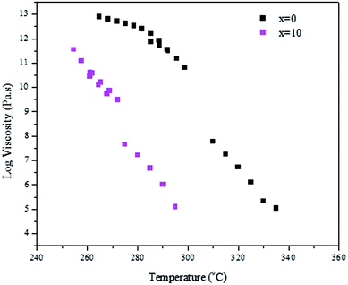
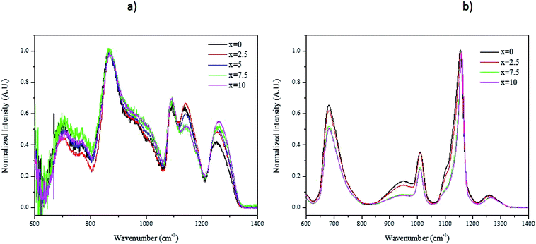
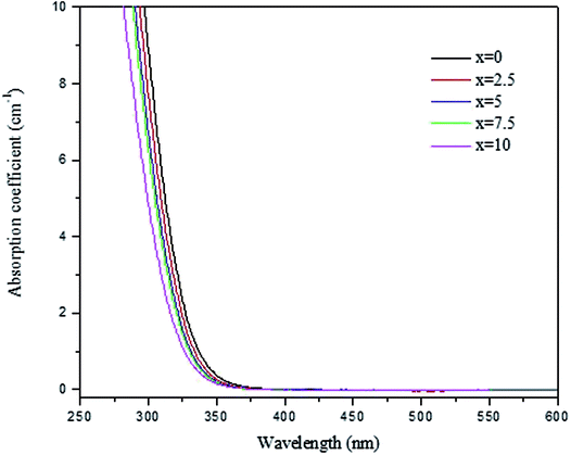
We successfully prepared phosphate glasses, which contain NaYF4:Er3+,Yb3+ nanocrystals, using the direct particles doping method.19 In this method, the nanocrystals need to be added in the glass melts after melting but prior to quenching to ensure the survival of the nanocrystals. First, a host glass in which the nanocrystals can be dispersed without being decomposed, needs to be identified. As explained in,20 two parameters need to be optimized when preparing a nanocrystals-containing glass using the direct particles doping method: the doping temperature (Tdoping) at which the nanocrystals are added in the glass batch and the dwell time before quenching the glass after adding the nanocrystals. The doping temperature should be lower than the nanocrystals' dissolution points, which was reported to be 750 °C.21 Furthermore, to avoid crystallization when adding the nanocrystals, the host glass must be stable against crystallization as checked by its ΔT (ΔT = Tx − Tg), which needs to be greater than 100 °C.Because of these requirements, we tested glasses with the composition (90NaPO3-(10-x)Na2O-xNaF) (mol%) because of their low melting temperature (750 °C). The density and the thermal properties of the glasses are reported in Table 1. When increasing x, the glass transition (Tg), the onset of crystallization (Tx) and the peak of crystallization (Tp) temperatures decrease in agreement with the shift of the viscosity of the glasses to lower temperature (Fig. 1). One can notice that an increase in x increases ΔT indicating that the F-containing glasses are stable against crystallization and so are good candidates for the direct doping method. Finally, whereas the changes in the glass composition has no significant impact on the glasses' density, the structure of the glasses changes as shown in Fig. 2a and b, which present the IR and Raman spectra of the glasses, respectively. The spectra are obviously relevant to the metaphosphate structure according to.22 The glasses are expected to be free of Q3 groups as there is no IR and Raman band at >1300 cm−1, where the ν(P![[double bond, length as m-dash]](https://www.rsc.org/images/entities/char_e001.gif) O) of Q3 groups usually appear. The attribution of the IR and Raman bands can be found in Table 2.23–31 The replacement of Na2O by NaF increases the number of Q2 units at the expense of Q1 units as seen by the increase in intensity of the shoulders in the 980–1050 cm−1 range and of the bands at 1080 cm−1 and at 1240 cm−1 and the decrease in intensity of the band at 1140 cm−1 with an increase in x (Fig. 2a). These changes in the structure induced by the increase in x can also be suspected from the shift of the Raman band at 1150 cm−1 to higher wavenumbers (Fig. 2b).26 The shortening of linear metaphosphate chains occurring when Na2O is replaced by NaF is evidenced by the small increase in intensity of the IR shoulder at 950 cm−1 and the decrease in intensity of the Raman band at 700 and 1250 cm−1 with an increase in x.28 The increase in the intensity of the IR shoulder at 1010 cm−1 can reveal an increase in the (PO3F) bonds as suggested in.27 The shift in the position of the IR bands to longer wavenumbers with an increase in x indicates the formation of F–P–F bonds when NaF replaces Na2O as suggested in.26 The increase in the amount of the Q2 units at the expense of the Q1 units, the formation of P–F bonds and to the reduction in non-bridging terminal groups are also supported by the shift of the optical band gap to a lower wavelengths (Fig. 3) as suggested by Venkateswara Rao.32 In summary, these changes in the glass structure lead to a decrease in the thermal properties of the glass when Na2O is replaced by NaF (Table 1 and Fig. 1). Therefore, the glass with x = 10 was selected for this study due to its low Tg and viscosity as compared to the glass with x = 0 and also due to its high ΔT. For comparison, the glass with x = 0 was also included in the study.
O) of Q3 groups usually appear. The attribution of the IR and Raman bands can be found in Table 2.23–31 The replacement of Na2O by NaF increases the number of Q2 units at the expense of Q1 units as seen by the increase in intensity of the shoulders in the 980–1050 cm−1 range and of the bands at 1080 cm−1 and at 1240 cm−1 and the decrease in intensity of the band at 1140 cm−1 with an increase in x (Fig. 2a). These changes in the structure induced by the increase in x can also be suspected from the shift of the Raman band at 1150 cm−1 to higher wavenumbers (Fig. 2b).26 The shortening of linear metaphosphate chains occurring when Na2O is replaced by NaF is evidenced by the small increase in intensity of the IR shoulder at 950 cm−1 and the decrease in intensity of the Raman band at 700 and 1250 cm−1 with an increase in x.28 The increase in the intensity of the IR shoulder at 1010 cm−1 can reveal an increase in the (PO3F) bonds as suggested in.27 The shift in the position of the IR bands to longer wavenumbers with an increase in x indicates the formation of F–P–F bonds when NaF replaces Na2O as suggested in.26 The increase in the amount of the Q2 units at the expense of the Q1 units, the formation of P–F bonds and to the reduction in non-bridging terminal groups are also supported by the shift of the optical band gap to a lower wavelengths (Fig. 3) as suggested by Venkateswara Rao.32 In summary, these changes in the glass structure lead to a decrease in the thermal properties of the glass when Na2O is replaced by NaF (Table 1 and Fig. 1). Therefore, the glass with x = 10 was selected for this study due to its low Tg and viscosity as compared to the glass with x = 0 and also due to its high ΔT. For comparison, the glass with x = 0 was also included in the study.
| x | Tg (°C) ±3 °C | Tx (°C) ±3 °C | ΔT = Tx − Tg (°C) ±3 °C | Tp (°C) ±3 °C | Density (g cm−3) ±0.02 g cm−3 |
|---|---|---|---|---|---|
| 0 | 284 | 374 | 90 | 414 | 2.47 |
| 2.5 | 272 | 378 | 106 | 415 | 2.47 |
| 5 | 264 | 374 | 110 | 403 | 2.47 |
| 7.5 | 255 | 368 | 113 | 395 | 2.46 |
| 10 | 246 | 356 | 110 | 402 | 2.45 |
| Wavenumber (cm−1) | Raman Shift | FTIR |
|---|---|---|
| 700 | νs(P–O–P) of Q2 and Q1 units23 | |
| 770 | νs(P–O–P) of Q2 units23 | |
| 880 | νas(P–O–P) of Q2 units23 | |
| 950 | νas(P–O–P) of Q2 units in small rings25 | |
| 980 | νs(PO4)3− in Q0 units28 | νs(PO32−) in Q1 units |
| 1010 | νs(P–O) of terminal Q1 units26 | νs(PO3F) bonds27 |
| 1030 | νas(P–O–P) of Q2 units in large rings25 | |
| 1080 | νas(PO3)2− in Q1 units28 | |
| 1150 | νs(PO2) of Q2 groups.29–31 | νs(PO32−) in Q2 units 24 |
| 1240 | νas(PO2) of Q2 groups.29–31 | νas(PO2) of Q2 units23 |
In the next stage, NaYF4:Er3+,Yb3+ nanocrystals were added in the glasses. In the doping process, one can identify four main factors that will influence the up-conversion behavior of the final products: (1) the thermal stability of the bare NaYF4:Er3+,Yb3+ nanocrystals, (2) the temperature of glass melt when adding the NaYF4:Er3+,Yb3+ nanocrystals, (3) the viscosity of the glass matrix, and (4) the homogeneity of the dispersion of the nanocrystals in the glass. Inhomogeneities in the dispersion of the nanocrystals will have rather straightforward effects on the up-conversion intensity observed at different parts of the glasses and thus this must be considered when comparing the intensities from different samples. The factors associated with points (1)–(3) are discussed in more detail below.
(1) It is known that the hexagonal NaRF4 (R = rare earth) structure will transform irreversibly to the high-temperature cubic structure at high temperature.33 The exact temperature will depend on the composition of the material,21 but for the present composition, it has been reported to be at 660 °C.34 This change in structure is driven by a gradual change in stoichiometry due to the loss of NaF from the NaRF4 matrix. The high-temperature cubic structure has only one site for the Er3+ ions, whereas the hexagonal one has three.33 Therefore, the shape of the spectra will be somewhat different for these two forms. Furthermore, the average R–R distances are longer in the cubic form than in the hexagonal one (cubic: 3.88 Å, hexagonal: 3.50 to 3.65 Å33). This results in less efficient energy transfer between Yb3+ and Er3+ lowering the intensity of the up-conversion emission. The cubic structure is also more centrosymmetric than the hexagonal one and thus it has less allowed transitions and hence lower emission intensity35 and one can expect longer emission lifetimes. It is also expected that the cross-relaxation mechanisms, which are an important de-excitation route for the green emission but do not affect the red one,36 will become less effective and thus the lifetime of the green emission would increase when the structure of the nanocrystals changes from hexagonal to cubic.37 On the other hand, it has been reported that the lifetime of the red up-conversion emission of Er3+ is shorter in the cubic than in the hexagonal form.38 It should be also noted that in bulk NaRF4 materials, the structural form can be easily identified with X-ray powder diffraction measurements, but in the present work the concentration of the NaYF4:Er3+,Yb3+ nanocrystals is too small to allow such identification.
(2) The heating of the glass matrix may decrease the structural transition temperature of the NaYF4:Er3+,Yb3+ nanocrystals and thus the structure can be partially or completely transformed to the high-temperature cubic phase in the process. The heating may also induce the corrosion of the nanocrystals either uniformly or a change in their composition. In the case of uniform corrosion, the relative concentrations of the R3+ would remain the same, but the particle size would decrease. Generally, a decrease in particle size leads to lower up-conversion intensity and shorter emission lifetimes.37 This can be associated with e.g. the increase in surface/volume ratio and subsequent increased surface-related quenching. If the composition changes due to corrosion, then it is expected that the up-conversion intensity decreases but the lifetimes increase for both the green37 and red39 emissions. In the present case, it is possible to also have the effect of NaF, which is present in the x = 10 glass and not on the x = 0 glass. Based on the discussion above, one would expect that the presence of NaF will make the hexagonal to cubic phase transition less probable and thus lessen its possible effects on the up-conversion properties.
(3) The glass matrix will affect the up-conversion properties. This is related to non-radiative quenching through the surface of the nanocrystals with the probability for such relaxation increasing with decreasing crystallite size. In this glass matrix, the surface quenching is likely to proceed via multiphonon de-excitation due to the fundamental vibrations of the phosphate Q2 units at around 1200 cm−1.40 Then, it takes only three such phonons to relax from the red-emitting 4F9/2 level to the NIR level 4I9/2 ca. 3000 cm−1 below. The green-emitting 4S3/2 also needs only three such phonons (ca. 3000 cm−1) to relax to the red-emitting 4F9/2 level and then three more to go to NIR. In phosphate glasses, the multiphonon decay rate for 3000 cm−1 energy gaps has been reported to be ca. 107 s−1,40 which is very high when compared to the millisecond range lifetimes associated with the up-conversion in Yb3+,Er3+ co-doped systems. Increased multiphonon relaxation is commonly associated with decreased up-conversion lifetimes.41
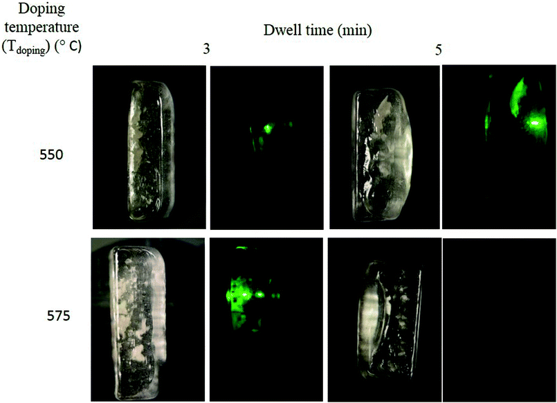
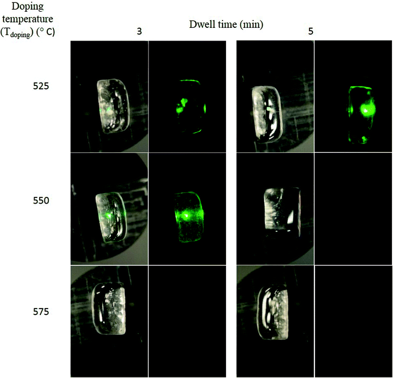
5 wt% of NaYF4:Er3+,Yb3+ nanocrystals were added in the glasses with x = 0 and 10 at Tdoping varying from 525 and 575 °C and the glasses were quenched after 3 and 5 min (dwell time) after adding the nanocrystals. It should be pointed out that the glass with x = 0 could not be quenched when using a Tdoping of 525 °C due to high viscosity. The glasses are labelled as (Tdoping-dwell time). As a first test, pictures of the glasses were taken in daylight and under pumping using 980 nm and are presented in Fig. 4 and 5, respectively for the glasses with x = 0 and 10. Under pumping at 980 nm, some glasses exhibit green emission which is a clear indication of the survival of the NaYF4:Er3+,Yb3+ nanocrystals in the glasses. While green emission can be seen from the (575-3) glass with x = 0, no green emission could be seen from the glass x = 10 when prepared using the same Tdoping of 575 °C. The Tdoping needed to be reduced to 550 °C to observe the green emission from the glass with x = 10. The reduction in the Tdoping from 575 to 550 °C when x increases from 0 to 10 to ensure the survival of the nanocrystals is in agreement with the changes in the thermal properties of the glasses when Na2O is replaced by NaF discussed in the previous paragraph. Since the beam size of the 980 nm laser is much smaller (ca. 2 mm in diameter) than the glass pieces, it is not possible to evaluate the dispersion of the nanocrystals based on emission intensity. However, under daylight, agglomerates of nanocrystals can be seen in some glasses. The (550-3) glass with x = 10 appears to be agglomerate-free. In both glass systems, the visually observed intensity of the green emission decreases with increasing Tdoping and longer dwell time.
The upconversion spectra of the glasses, crushed into powder for the analysis, were measured using 980 nm pumping and the spectra are presented in Fig. 6. The spectra exhibit green (2H11/2–4I15/2 and 4S3/2–4I15/2) and red (4F9/2–4I15/2) emission, which are typical emissions for Er3+.9 The upconversion spectra of the nanocrystals-containing glasses exhibit distinct fine structure, which is a characteristic of Er3+ ions coordinated in crystalline sites confirming the presence of NaYF4:Er3+,Yb3+ nanocrystals in the glasses. As a general observation and in agreement with the pictures presented in Fig. 4 and 5, the glasses with x = 10 exhibit stronger upconversion than the glasses with x = 0, which is also in agreement with our previous study.19 Additionally, an increase in Tdoping and in dwell time leads to a reduction in the intensity of the green and red emission. As discussed above, this may be due to the increase of the concentration of the cubic NaYF4 structure initiated by heating at a higher temperature or for a longer time. We also confirm that the (550-3) glass with x = 10 exhibits a strong intensity of upconversion. Compared to our previous study,19 we showed that the upconversion from the investigated fluorophosphate glasses can be further enhanced if the Tdoping is reduced to 550 °C.
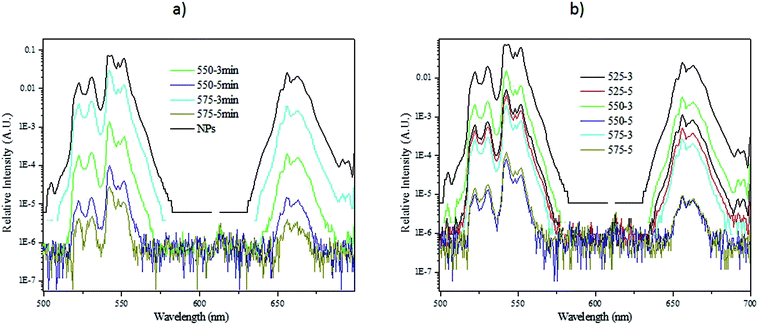 | ||
| Fig. 6 Upconversion spectra of the NaYF4:Er3+,Yb3+ nanocrystals-containing glasses with x = 0 (a) and 10 (b) using a 980 nm excitation. Note the logarithmic intensity scales. | ||
Furthermore, one can notice that the (575-3) glass with x = 0 exhibits a higher intensity of upconversion compared to the other glasses. Based on Fig. 4 and 5, this strong upconversion is suspected to come from the agglomerates of nanocrystals seen in the glass. However, the agglomerates of nanocrystals in the glasses are reducing the amount of nanocrystals dispersed in the glass, which in turn results in a lower upconversion than expected. This is the case for the (525-3) glass with x = 10 which exhibits a lower upconversion than the (550-5) glass with x = 10. Therefore, it is crucial to compare the upconversion spectra of the glasses with the pictures of the glasses under pumping when optimizing the direct particles doping method.
Fig. 7 exhibit the red up-conversion emission band of the glasses with x = 10 when normalizing to the green emission. An increase in the Tdoping and the dwell time decreases the intensity of the red emission as compared to the green emission. These results indicate that the quenching of the red emission becomes more effective than that of the green one probably due to the decrease of the relative concentration of Er3+ in the nanocrystals which may be either due to the leakage of the Er3+ ions from the crystal to the glass, as reported previously by us,19,42,43 or due to the increase of the amount of the cubic phase as discussed above.
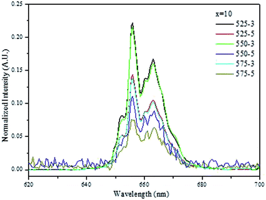 | ||
| Fig. 7 Red emission band when the upconversion spectra of the NaYF4:Er3+,Yb3+ nanocrystals-containing glasses with x = 10 are normalized to the green emission. | ||
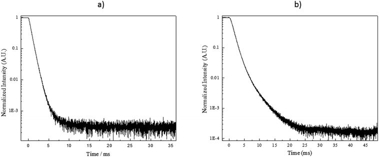
To gain further information on the processes affecting the NaYF4:Yb3+,Er3+ nanocrystals, the up-conversion decay curves were measured for the green and red emissions. The data were then fitted with a two-term exponential function as illustrated in Fig. 8. The results related to the green and red emission are summarized in Fig. 9a and b, respectively. It should be pointed out that the estimated decay times are not the actual decay times of the emitting states of the Er3+ but they are the apparent decay times for the detected emissions, which result from the complex excitation and emission system between Yb3+ and Er3+ ions.
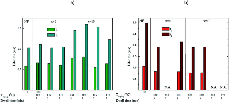 | ||
| Fig. 9 Lifetimes of the green (a) and red (b) up-conversion emissions in the NCs alone and in the investigated glasses. All were excited at 975 nm with a 0.9 V voltage except *0.1 V, **0.2 V and ***0.5 V. The voltage is expected to have only a small impact on the lifetimes as reported in ref 45. In the cases marked with N.A., the lifetimes could not be measured due to a too low signal intensity. | ||
For the green emission (Fig. 9a), the lifetimes are slightly longer in the x = 0 glasses while the lifetimes are clearly longer in the x = 10 glasses than for the bare NCs. When comparing the effect of the doping parameters on the lifetimes of the green emission, we notice that for the x = 0 glasses, the lifetime decreases when the Tdoping and dwell time increase suggesting that homogeneous corrosion of the NCs occurs in these glasses. For the x = 10 glasses, the lifetime increases when the Tdoping increases from 525 to 550 °C while using 3 min dwell time indicating that the Er3+ concentration in the nanocrystals decreases after embedding the nanocrystals in the glass. However, when preparing the glasses using higher Tdoping and longer dwell times, the lifetimes decrease suggesting a homogeneous corrosion of the NCs. The marked difference between the lifetimes in the x = 0 and x = 10 glasses is probably due to the effect of NaF in the latter. We propose that NaF acts as a diluting agent for the NCs thus decreasing the Er3+ concentration and increasing the green emission lifetimes.
For the red emission (Fig. 9b), our results show that incorporating the nanocrystals into the glass matrices decreases the lifetimes probably due to an increase in the multiphonon de-excitation when the NCs are embedded into the glass.41 It is also possible that the crystallite size of the NCs decreases during the glass processing, decreasing further the lifetimes.37 As explained in the previous paragraph, the increase in the green lifetime can indicate that the concentration of the rare-earth decreases in the nanocrystals according to.37,39 However, we are left with the question of why the red lifetimes do not increase. We propose that it is because the red emission may be considered as a three-photon pile-up36 whereas the green is a two-photon one. Therefore, the red emission would be more drastically affected by the surface quenching caused by the glass matrix than the green one. Finally, the evolution of the red lifetimes as a function of the Tdoping and dwell time is more difficult to explain than that of the green lifetimes. It seems as if there is no impact at all from changes in temperature or time. At the moment, it is impossible to suggest why that is, other than a complex interplay of the effects described above.
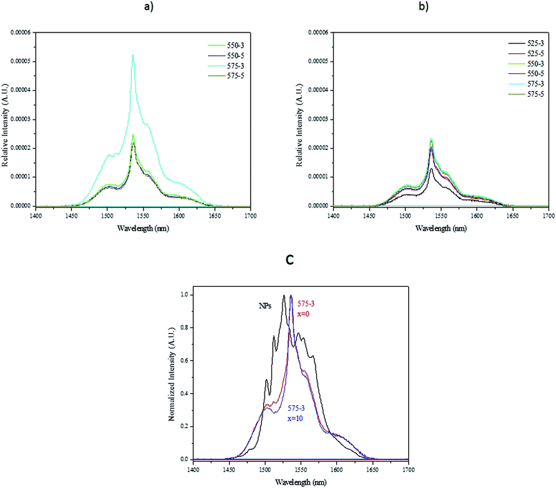
The down-shifting emission spectra of the nanocrystals-containing glasses with x = 0 and 10 using a 980 nm pumping spectra are depicted in Fig. 10a and b, respectively. They exhibit a broad emission band which is different from the emission spectra of the nanocrystals alone (Fig. 10c) confirming the changes in the Er3+ sites after embedding the nanocrystals in the glasses. We propose that the spectrum is an overlay of the emission of Er3+ in the NCs as well as those leaked to the glass matrix, probably having mostly emission from latter ones. The rounded shapes of the peaks suggest that Er3+ has multiple sites with close to similar symmetries as is typical for glasses. Because the up-conversion spectra revealed no differences between the bare NCs and those embedded into the glass, we can deduce that only the Er3+ ions in the NCs show up-conversion emission. One can notice that the glasses exhibit similar intensity of emission at 1.5 μm except for the (575-3) glass with x = 0 which exhibits a high intensity of emission. This can be associated with the highest amount of Er3+ ions leaked to the glass matrix at this highest Tdoping. For the x = 10 glasses, such drastic increase is not observed because the NaF present probably slows down the corrosion of the nanocrystals.
Although a transmission electron microscope (TEM) can be used to characterize the nanocrystals embedded in the glasses as in,44 it is extremely challenging to perform the analysis due to the small volume fraction of the NCs when compared to the glass and also due to the small size of the NCs as reported in.20 Therefore, it is shown here that simple measurement as upconversion spectra measurement can be used to check if decomposition of the nanocrystals occurs during the glass melting. Therefore, based on Fig. 10, we confirm that 550 °C is an appropriate Tdoping when preparing the glass with x = 10. This Tdoping allows the dispersion of the nanocrystals in the glass while limiting their decomposition. As the (575-3) glass exhibits a more intense red emission than the (550-5) glass, we suspect the dwell time to have a stronger impact than the Tdoping on the decomposition of the nanocrystals. Therefore, the dwell time needs to be controlled to limit the decomposition: the 5 min dwell time before quenching the glass after adding the nanocrystals at 550 °C seems to be already long enough to lead to the decomposition of the nanocrystals.
In order to verify the decomposition of the nanocrystals during the preparation of the glass, the transmittance spectra of the glasses were measured and they are presented in Fig. 11. As seen previously,19 the nanocrystals-containing glasses exhibit a lower transmittance than the nanocrystals-free glasses due to the presence of nanocrystals as explained in.20 One can notice that an increase in Tdoping and dwell time increases the transmittance of the glasses confirming the decomposition of the nanocrystals in the glasses.
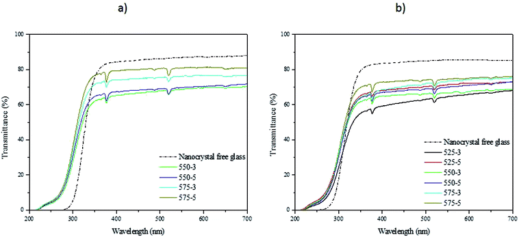 | ||
| Fig. 11 Transmittance spectra of the NaYF4:Er3+,Yb3+ nanocrystals-free and containing glasses with x = 0 (a) and 10 (b). | ||
Conclusion
Upconverter fluorophosphate glasses were prepared by adding in the glass melt NaYF4:Er3+,Yb3+ nanocrystals using the direct particles doping method. First we investigated the effect of NaF addition at the expense of Na2O on the thermal, physical, optical and structural properties of glasses in the system (90NaPO3-(10-x)Na2O-xNaF) (mol%). Using IR and Raman spectroscopies, we found that an increase in the NaF content (x) leads to an increase in the number of Q2 units at the expense of the Q1 units, a shift of the optical band gap to lower wavelengths and so to a decrease in the thermal properties of the glasses. As compared to our previous work,15 the upconversion from the glasses can be further enhanced by optimizing the direct particles doping method: a strong and homogeneous upconversion can be obtained by adding at 550 °C the NaYF4:Er3+,Yb3+ nanocrystals in the glass melt with x = 10. The glass should be quenched 3 minutes after adding the nanocrystals to ensure the survival and the dispersion of the nanocrystals in the glass while limiting their decomposition in the glass melts. Finally, we demonstrated that the measurement of the upconversion, upconversion emission lifetimes, the emission at 1.5 μm and of the transmittance spectra of the nanocrystals-containing glasses allows one to verify if decomposition of the nanocrystals occurred in glass melts.These results provide important new information on the preparation of nanocrystals-containing fluorophosphates glasses using direct particles doping method. This method offers the possibility of preparing a variety of new glasses by introducing nanocrystals of various chemical compositions.
Conflicts of interest
The authors declare no conflict of interest. The funding sponsors had no role in the design of the study; in the collection, analyses, or interpretation of data; in the writing of the manuscript and in the decision to publish the results.Acknowledgements
The authors would like to acknowledge Hoang Nguyen (from Tampere University of Technology, Finland) for preparing the nanocrystals-free glasses, Dr Salminen (from Tampere University of Technology, Finland) for measuring the Raman spectra of the glasses and also Prof. Delia Brauer and Thilo Grammes (from Friedrich Schiller University, Germany) for performing the viscosity measurement. LP would like to acknowledge the financial support of the Academy of Finland (Academy Project-308558) and MT the financial support from the Magnus Ehrnrooth foundation (Finland).References
- W. S. Tsang, W. M. Yu, C. L. Mak, W. L. Tsui, K. H. Wong and H. K. Hui, J. Appl. Phys., 2002, 91, 1871 CrossRef.
- G. S. Qin, W. P. Qin, C. F. Wu, S. H. Huang, J. S. Zhang, S. Z. Lu, D. Zhao and H. Q. Liu, J. Appl. Phys., 2003, 93, 4328 CrossRef.
- S. Sanders, R. G. Waarts, D. G. Mehuys and D. F. Wetch, Appl. Phys. Lett., 1995, 67, 1815–1817 CrossRef.
- J. Zhang, S. Dai, G. Wang, L. Zhang, H. Sun and L. Hu, Phys. Lett. A, 2005, 345, 409–414 CrossRef.
- H. Lin, E. Y. B. Pun and X. R. Liu, J. Non-Cryst. Solids, 2001, 283, 27 CrossRef.
- N. M. Idris, M. K. G. Jayakumar, A. Bansal and Y. Zhang, Chem. Soc. Rev., 2015, 44, 1449–1478 RSC.
- W. Zheng, P. Huang, D. Tu, E. Ma, H. Zhu and X. Chen, Chem. Soc. Rev., 2015, 44, 1379–1415 RSC.
- Y. I. Park, K. T. Lee, Y. D. Suh and T. Hyeon, Chem. Soc. Rev., 2015, 44, 1302–1317 RSC.
- F. Auzel, Chem. Rev., 2004, 104, 139–173 CrossRef PubMed.
- J. Ruan, Z. Yang, A. Huang, H. Zhang, J. Qiu and Z. Song, ACS Appl. Mater. Interfaces, 2018, 10, 14941–14947 Search PubMed.
- Y. Wang and J. Ohwaki, Appl. Phys. Lett., 1993, 63, 3268 CrossRef.
- P. A. Tick, N. F. Borrelli, L. K. Cornelius and M. A. Newhouse, J. Appl. Phys., 1995, 78, 6367 CrossRef.
- T. Berthier, V. M. Fokin and E. D. Zanotto, J. Non-Cryst. Solids, 2008, 354, 1721–1730 CrossRef.
- G. Y. Chen, C. H. Yang and P. N. Prasad, Acc. Chem. Res., 2013, 46, 1474–1486 CrossRef PubMed.
- B. S. Cao, Y. Y. He, L. Zhang and B. Dong, J. Lumin., 2013, 135, 128–132 CrossRef.
- Y. Gao, Y. Hu, D. Zhou and J. Qiu, J. Alloys Compd., 2017, 699, 303–307 CrossRef.
- F. Liu, E. Ma, D. Chen, Y. Wang, Y. Yu and P. Huang, J. Alloys Compd., 2009, 467, 317–321 CrossRef.
- A. de Pablos-Martín, J. Méndez-Ramos, J. del-Castillo, A. Durán, V. D. Rodriguez and M. J. Pascual, J. Eur. Ceram. Soc., 2015, 35, 1831–1840 CrossRef.
- H. Nguyen, M. Tuomisto, J. Oksa, T. Salminen, M. Lastusaari and L. Petit, Scr. Mater., 2017, 139, 130–133 CrossRef.
- J. Zhao, X. Zheng, E. P. Schartner, P. Ionescu, R. Zhang, T.-L. Nguyen, D. Jin and H. Ebendorff-Heidepriem, Adv. Opt. Mater., 2016 DOI:10.1002/adom.201600296.
- T. Laihinen, M. Lastusaari, L. Pihlgren, L. C. V. Rodrigues and J. Hölsä, J. Therm. Anal. Calorim., 2015, 121, 37–43 CrossRef.
- K. Meyer, J. Non-Cryst. Solids, 1997, 209, 227–239 CrossRef.
- I. Konidakis, C.-P. E. Varsamis, E. I. Kamitsos, D. Möncke and D. Ehrt, J. Phys. Chem., 2010, 114, 9125–9138 Search PubMed.
- K. Griebenow, C. B. Bragatto, E. I. Kamitsos and L. Wondraczek, J. Non-Cryst. Solids, 2018, 481, 447–456 CrossRef.
- J. A. Wilder and J. E. Shelby, J. Am. Ceram. Soc., 1984, 67, 438–444 CrossRef.
- S. Cui, J. Massera, M. Lastusaari, L. Hupa and L. Petit, J. Non-Cryst. Solids, 2016, 445, 40–44 CrossRef.
- M. K. Murthy, J. Am. Ceram. Soc., 1963, 46, 558–559 CrossRef.
- R. K. Brow, J. Non-Cryst. Solids, 2000, 263, 1–28 CrossRef.
- S. Lee, A. Obata and T. Kasuga, J. Ceram. Soc. Jpn., 2009, 117, 935–938 CrossRef.
- M. A. Karakassides, A. Saranti and I. Koutselas, J. Non-Cryst. Solids, 2004, 347, 69–79 CrossRef.
- A. G. Kalampounias, J. Phys. Chem. Solids, 2012, 73, 148–153 Search PubMed.
- G. Venkateswara Rao and H. D. Shashikala, J. Adv. Ceram., 2014, 3, 109–116 CrossRef.
- E. Harju, I. Hyppänen, J. Hölsä, J. Kankare, M. Lahtinen, M. Lastusaari, L. Pihlgren and T. Soukka, Z. Kristallogr. Proc., 2011, 1, 381–387 Search PubMed.
- I. Hyppänen, J. Hölsä, J. Kankare, M. Lastusaari, L. Pihlgren and T. Soukka, Terrae Rarae, 2009, 16, 1–6 Search PubMed.
- A. Noculak and A. Podhorodecki, Nanotechnology, 2017, 28, 175706 CrossRef PubMed.
- M. T. Berry and P. S. May, J. Phys. Chem. A, 2015, 119, 9805–9811 CrossRef PubMed.
- A. Kar, S. Kundu and A. Patra, ChemPhysChem, 2015, 16, 505–521 CrossRef PubMed.
- E. Palo, L. Pihlgren, M. Tuomisto, T. Laihinen, I. Hyppänen, J. Kankare, M. Lastusaari, T. Soukka, H. Swart and J. Hölsä, Opt. Mater., 2016, 59, 49–54 CrossRef.
- S. Georgescu, V. Lupei, A. Lupei, V. I. Zhekov, T. M. Murina and M. I. Studenikin, Opt. Commun., 1991, 81, 186–192 CrossRef.
- C. B. Layne, W. H. Lowdermilk and M. J. Weber, Phys. Rev. B, 1977, 16, 10–21 CrossRef.
- I. Hyppänen, N. Höysniemi, R. Arppe, M. Schäferling and T. Soukka, J. Phys. Chem. C, 2017, 121, 6924–6929 Search PubMed.
- J. Massera, P. Głuchowski, M. Lastusaari, L. C. V. Rodrigues, L. Petit, J. Hölsä, L. Hupa and M. Hupa, J. Eur. Ceram. Soc., 2015, 35, 1255–1261 CrossRef.
- J. Massera, M. Gaussiran, P. Głuchowski, M. Lastusaari, L. C. V. Rodrigues, L. Petit, J. Hölsä and L. Hupa, Opt. Mater., 2016, 52, 56–61 CrossRef.
- J. Zhao, Z. Yang, C. Yu, J. Qiu and Z. Song, Chem. Eng. J., 2018, 341, 175–186 CrossRef.
- X. Xue, M. Thitsa, T. Cheng, W. Gao, D. Deng, T. Suzuki and Y. Ohishi, Opt. Express, 2016, 24, 26307 CrossRef PubMed.
| This journal is © The Royal Society of Chemistry 2018 |

