 Open Access Article
Enhanced device performance and stability of perovskite solar cells with low-temperature ZnO/TiO2 bilayered electron transport layers†
Caifeng Zhangabc,
Guangmei Zhai *abc,
Yong Zhangacd,
Wenhui Gaoac,
Zhimeng Shaoac,
Lulu Zhengac,
Fuhong Meiac,
Hua Zhang*ac,
Yongzhen Yang
 ac,
Xuemin Liac,
Xuguang Liu
 acd and
Bingshe Xuac
aKey Laboratory of Interface Science and Engineering in Advanced Materials of Ministry of Education, Research Centre of Advanced Materials Science and Technology, Taiyuan University of Technology, Taiyuan, Shanxi 030024, China. E-mail: zhaiguangmei@tyut.edu.cn; zhanghua01@tyut.edu.cn
bCAS Key Laboratory of Renewable Energy, Guangzhou 510640, China
cCollaborative Innovation Centre for Advanced Thin-film Optoelectronic Materials and Devices in Shanxi Province, Taiyuan, Shanxi 030024, China
dCollege of Materials Science and Engineering, Taiyuan University of Technology, Taiyuan, Shanxi 030024, China
First published on 22nd June 2018
Abstract
The instability of perovskite films is a major issue for perovskite solar cells based on ZnO electron transport layers (ETLs). Here, ZnO nanoparticle (NP)- and ZnO sol–gel layers capped with low-temperature processed TiO2, namely ZnO/TiO2 bilayered films, have been successfully employed as ETLs in highly efficient MAPbI3-based perovskite solar cells. It is demonstrated that these ZnO/TiO2 bilayered ETLs are not only capable of enhancing photovoltaic performance, but also capable of improving device stability. The best device based on the ZnO/TiO2 bilayered ETL exhibits an efficiency of ∼15% under standard test conditions and can retain nearly 100% of its initial efficiency after 30 days of atmosphere storage, showing much higher device performance and stability compared to those devices based on ZnO single-layer ETLs. Moreover, it is found that perovskite films and devices prepared on the single ZnO sol–gel ETLs are much superior to those deposited on the single ZnO NP-ETLs in both stability and performance, which can be ascribed to fewer surface hydroxyl groups and much smoother surface morphology of the ZnO sol–gel films. The results pave the way for ZnO to be used as an effective ETL of low-temperature processed, efficient and stable PSCs compatible with flexible substrates.
Introduction
Organic–inorganic hybrid perovskite solar cells (PSCs) have drawn much attention in the past several years as the power conversion efficiency (PCE) increases quickly from preliminary 3.8% to 22.7% in the present day.1,2 Although the excellent performance of PSCs is fundamentally due to perovskite materials' excellent electronic and optical properties, such as direct bandgap structures, high light absorption coefficients, high carrier mobilities, low exciton binding energies and long carrier diffusion lengths,3–5 technically it is also related to their device structure. PSCs either in a normal (n–i–p) structure or an inverted (p–i–n) structure are generally composed of a transparent conductive layer, an electron transport layer (ETL), a light absorption perovskite layer, a hole transport layer and a metal electrode layer. Among these layers, ETL works as an electron selective contact, playing an important role in extracting electrons from the light absorbing layer and suppressing charge recombination,6–8 and thus significantly affects the final performance of PSCs. To date, the most widely used ETL material in perovskite photovoltaic devices is TiO2, based on which highly efficient PSCs with power conversion efficiencies exceeding 20% have been produced. However, TiO2 usually requires a high sintering temperature (∼500 °C) to obtain its anatase phase for most of the highly efficient perovskite devices in the normal device structure, which not only increases their producing cost but also hinders the development of flexible devices on plastic substrates.9 Therefore, the exploration of low-temperature processed ETLs for PSCs is highly desirable. So far, several low-temperature processable ETL materials including ZnO8 and SnO210,11 have been developed. Specifically, as a wide band gap semiconductor, ZnO can achieve high crystalline quality even at low temperature.12 Moreover, ZnO has a suitable work function, outstanding light transmittance and a high electron mobility.13 All of these remarkable optoelectronic properties of ZnO make it an attractive ETL candidate in PSCs. Some efforts have been made in low-temperature ZnO-based PSCs. Kelly et al.8 successfully employed ZnO nanoparticle (NP)-ETLs to fabricate CH3NH3PbI3-based planar heterojunction PSCs with high efficiency at room temperature. Elumalai and Uddin et al.14 used a simple, low-temperature (<150 °C) processed sol–gel ZnO thin film as ETL for CH3NH3PbI3-based perovskite solar cells and achieved a PCE of 8.77%. However, perovskite films deposited atop ZnO layers encounter a severe instability issue, which would adversely affect the application of these devices.15,16 To alleviate the instability problem, several strategies have been reported, such as doping17,18 and surface modification/passivation.15,19 Although the stability of ZnO based devices has been indeed improved by means of these strategies, either their performance is still poor or high-temperature processes are involved in some strategies.In this work, we develop a facile and effective method of improving the stability of ZnO-based PSCs, in which low-temperature processed TiO2 was deposited on top of either ZnO NP- or ZnO sol–gel layers to form ZnO/TiO2 bilayered ETLs for perovskite solar cells. Compared with those ZnO single-layer ETLs, not only stability but also photovoltaic performance of the devices based on the ZnO/TiO2 bilayer-ETLs was substantially enhanced. Moreover, interestingly we found that the perovskite films prepared via “one-step” deposition on the ZnO sol–gel ETLs are much superior to those deposited on the ZnO NP-ETLs in both stability and device performance. Since the entire device fabrication can be processed at less than 150 °C, it is expected that the ZnO/TiO2 bilayer-ETLs reported here would have great application potential in flexible devices with roll-to-roll processes.
Experimental
Materials
Ti-nanoxide T-L/SC was purchased from Solaronix, Switzerland. N,N-dimethylformamide (DMF, ≥99.8%), dimethyl sulfoxide (DMSO, ≥99.5%), chlorobenzene (99.8%), acetonitrile (99.9%), 4-tert-butylpyridine (TBP, >96.0%), and bistri-fluoromethanesulfonimide lithium (Li-TFSI, 99.95%) were ordered from Sigma-Aldrich. Lead iodide (PbI2, 99.999%) and CH3NH3I (MAI, 99%) were obtained from Shanghai MaterWin New Materials Co., Ltd. Diethyl ether, zinc acetate dihydrate, methanol, n-butanol, chloroform, 2-methoxyethanol, ethanolamine were purchased from Sinopharm Chemical Reagent Co., Ltd. 2,2′,7,7′-tetrakis[N,N-Di(4-methoxyphenyl)amino]-9,9′-spiro-bifluorene (spiro-OMeTAD, >99.5%) and gold electrode (99.999%) were ordered from Luminescence Technology Corp. and Zhongnuo Advanced Material Technology Co., Ltd, respectively. All the chemicals were used as received without any further purification.Device fabrication
The ZnO NPs and ZnO sol–gel were prepared according to the methods reported in literatures 8 and 20, respectively. All of the devices were fabricated on fluorine-doped tin oxide (FTO, 7 ± 1 Ω □−1) glass substrates. These FTO substrates were cleaned orderly by ultrasonication in detergent, DI water, acetone and ethanol for 15 min, respectively. Then the substrates were blow dried with N2 and treated with ultraviolet/ozone for 15 min before the fabrication of solar cells. For the ZnO-NP films, the as-prepared ZnO NP-solution (around 6 mg mL−1 in the mixture of n-butanol, methanol and chloroform) was spin-coated onto the substrate at 2500 rpm for 30 s and then annealed on a hot plate at 130 °C for 10 min in air. The procedure was repeated again to obtain a continuous, smooth film. For the ZnO sol–gel films deposited by a low temperature method, the ZnO sol–gel precursor solution was spin-coated onto the substrate at 4000 rpm for 30 s and then annealed on a hot plate at 140 °C for 30 min in air. The procedure was also repeated once. To construct the ZnO NPs/TiO2 and ZnO sol–gel/TiO2 bilayered films, the Ti-nanoxide T-L/SC was first diluted to half of its original concentration in order to get an optimal film thickness. Then the solution was spin-coated onto the ZnO-NP film or ZnO sol–gel film at 4000 rpm for 30 s, followed by annealing at 150 °C for 30 min. The thicknesses of these ZnO-NP, ZnO sol–gel, and TiO2-NP films are around 50 nm, 50 nm, and 60 nm, respectively. Then the substrates were transferred into a N2-filled glovebox. The perovskite layers were deposited on the obtained ETLs by a “one-step” deposition method.21 The perovskite precursor solution containing 484 mg PbI2, 159 mg MAI and 71 μL DMSO (molar ratio 1.05![[thin space (1/6-em)]](https://www.rsc.org/images/entities/char_2009.gif) :
:![[thin space (1/6-em)]](https://www.rsc.org/images/entities/char_2009.gif) 1
1![[thin space (1/6-em)]](https://www.rsc.org/images/entities/char_2009.gif) :
:![[thin space (1/6-em)]](https://www.rsc.org/images/entities/char_2009.gif) 1) in 635 μL DMF was spin-coated at 4000 rpm for 30 s, and then 500 μL of diethyl ether was continuously dripped onto the rotating substrate in 8 s. Subsequently the as-prepared transparent intermediate phase films were heated in order at 65 °C for 1 min and at 100 °C for 2 min to obtain compact perovskite films. After cooling down to room temperature, a spiro-OMeTAD based HTL precursor [72.3 mg spiro-OMeTAD, 29 μL TBP and 18 μL Li-TFSI solution (520 mg mL−1 Li-TFSI solution in acetonitrile) all dissolved in 1 mL chlorobenzene] was spin-coated on the perovskite layer at 3000 rpm for 30 s to form a smooth HTL. Then the samples with HTL were left overnight in an electronic dry cabinet (≤15% RH) for oxidation. Finally, an Au electrode was deposited on top of the spiro-OMeTAD layer by thermal evaporation.
1) in 635 μL DMF was spin-coated at 4000 rpm for 30 s, and then 500 μL of diethyl ether was continuously dripped onto the rotating substrate in 8 s. Subsequently the as-prepared transparent intermediate phase films were heated in order at 65 °C for 1 min and at 100 °C for 2 min to obtain compact perovskite films. After cooling down to room temperature, a spiro-OMeTAD based HTL precursor [72.3 mg spiro-OMeTAD, 29 μL TBP and 18 μL Li-TFSI solution (520 mg mL−1 Li-TFSI solution in acetonitrile) all dissolved in 1 mL chlorobenzene] was spin-coated on the perovskite layer at 3000 rpm for 30 s to form a smooth HTL. Then the samples with HTL were left overnight in an electronic dry cabinet (≤15% RH) for oxidation. Finally, an Au electrode was deposited on top of the spiro-OMeTAD layer by thermal evaporation.
Characterization
The X-ray diffraction (XRD) with Cu Kα radiation (1.5418 Å) was performed on a Y-2000 Automated X-ray diffractometer or a Rigaku Smart Lab SE X-ray diffractometer. The Fourier transform infrared (FT-IR) spectra were recorded on a Bruker Tensor 27 infrared spectrometer. The surface chemical compositions of films were characterized by X-ray photoelectron spectroscopy (XPS, ESCALAB 250Xi, Thermo Fisher). The surface morphologies of films were obtained using a JSM-6700F field emission scanning electron microscope (SEM) and the surface roughness was measured with a NSK SPA-300HV atomic force microscope (AFM). The absorbance and transmittance spectra were recorded by a Perkin Elmer Lambda 950 UV-Vis-NIR spectrometer. The current density–voltage (J–V) characteristics of the devices were measured with a PVIV-3A solar cell measurement system including a solar simulator and a Keithley 2400 source meter at room temperature. The AM 1.5G illumination of 100 mW cm−2 was calibrated by using a standard Si reference cell certificated by the National Institute of Metrology, China. The effective area of cells was defined as 3 mm2.Results and discussion
Fig. 1 shows the transmittance spectra and SEM images of a ZnO-NP film, a ZnO sol–gel film, a ZnO NPs/TiO2 bilayered film and a ZnO sol–gel/TiO2 bilayered film. It can be clearly seen from Fig. 1(a) and (d) that both the ZnO-NP film and the ZnO sol–gel film possess similar transmittance values (≥80%) to those of their ZnO/TiO2 bilayered counterparts over the entire spectral range from 400 nm to 800 nm, indicating that the TiO2 capping layers have no negative effects on ETLs' optical characteristics. The SEM images [Fig. 1(b), (c), (e) and (f)] show that the ZnO-NP film is much rougher than the ZnO sol–gel film, causing the slightly uneven surface of the ZnO NPs/TiO2 bilayered film compared to the ZnO sol–gel/TiO2 bilayered film, while both TiO2 top layers are relatively dense. The XRD patterns of these films were obtained by grazing-incidence X-ray diffraction measurements and shown in Fig. S1.† As can be seen from Fig. S1,† (100), (101) and (110) characteristic diffraction peaks of hexagonal ZnO at 2θ = 31.6°, 36.1° and 56.6°, respectively, are distinguishable for the ZnO-NP film. However, no clear characteristic peaks can be observed for the ZnO sol–gel film, indicating that the crystallization of the ZnO sol–gel film is much worse than the ZnO-NP film. Moreover, only weak (101) characteristic diffraction peaks of anatase TiO2 at 2θ = 25.3° can be observed in the XRD patterns of those ZnO NPs/TiO2, ZnO sol–gel/TiO2, and TiO2 films, suggesting that these low-temperature ETLs are less crystallized.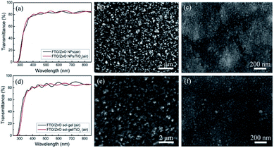 | ||
| Fig. 1 Transmittance spectra (a and d) and SEM images of (b) a ZnO-NP film, (c) a ZnO NPs/TiO2 bilayered film, (e) a ZnO sol–gel film, and (f) a ZnO sol–gel/TiO2 bilayered film. | ||
Following the processes stated in the experimental section, MAPbI3 perovskite films were deposited on these four ETLs and then annealed in N2 at 100 °C to evaluate their stability. Fig. 2(a) shows the photographs of MAPbI3 films deposited on the ZnO-NP film and the ZnO NPs/TiO2 bilayered film before and after the thermal treatment. It can be seen that both MAPbI3 films on the ZnO-NP film and the ZnO NPs/TiO2 bilayered film are initially dark brown. After annealing at 100 °C for 10 min, the MAPbI3 film on the ZnO-NP film turned light brown, indicating that the perovskite film had partly decomposed. When the annealing time was prolonged to 20 min, the MAPbI3 film on the ZnO-NP film had predominantly become yellowish, reflecting a basically complete decomposition of perovskite into PbI2. However, the MAPbI3 perovskite film on the ZnO NPs/TiO2 bilayered film was still dark brown after annealing for 20 min and could even remain unchanged in a prolonged period of time, manifesting that the low-temperature ZnO NPs/TiO2 bilayered film can significantly improve the stability of perovskite films compared with the single ZnO-NP film. Fig. 2(b) shows the photographs of MAPbI3 films on the ZnO sol–gel film and the ZnO sol–gel/TiO2 bilayered film before and after the thermal treatment. At the beginning, the MAPbI3 films deposited on both the ZnO sol–gel film and the ZnO sol–gel/TiO2 film are also dark brown, same as those on the ZnO-NP film and the ZnO NPs/TiO2 film. Unexpectedly, the MAPbI3 film deposited on the ZnO sol–gel film showed much higher thermal stability than that on the ZnO-NP film. As shown in Fig. 2(b), even after annealing at 100 °C for 100 min, only the marginal part of the film slightly turned yellow while the most area still remained the same dark brown as the perovskite on the ZnO sol–gel-TiO2 bilayered film. This indicates that the stability of perovskite on the ZnO sol–gel films is only slightly lower than that on the ZnO sol–gel/TiO2 bilayered films, but much higher than that on the ZnO-NP films.
In order to understand their difference in stability, we investigated the surface chemistry of these four ETLs by XPS measurements. As shown in Fig. 3, the O 1s core level spectra can be deconvoluted into two main peaks located at 530.0 eV (or 529.5 eV) and 531.4 eV, which correspond to the O 1s core level in ZnO (and/or TiO2) and the chemisorbed oxygen species such as hydroxyl (OH−), respectively. Their Zn 2p and Ti 2p core level spectra are shown in Fig. S2.† It is generally believed that hydroxyls on the surface of ZnO are the origin of the decomposition of perovskite.15,16 Hydroxyls on the film surface are derived from dissociated and molecularly adsorbed water.22 For the ZnO-NP film, the ratio of O in hydroxyls and O in ZnO NPs is 0.688![[thin space (1/6-em)]](https://www.rsc.org/images/entities/char_2009.gif) :
:![[thin space (1/6-em)]](https://www.rsc.org/images/entities/char_2009.gif) 1, however the ratio of O in hydroxyls and O in TiO2 (and/or ZnO NPs) decreases to 0.307
1, however the ratio of O in hydroxyls and O in TiO2 (and/or ZnO NPs) decreases to 0.307![[thin space (1/6-em)]](https://www.rsc.org/images/entities/char_2009.gif) :
:![[thin space (1/6-em)]](https://www.rsc.org/images/entities/char_2009.gif) 1 for the ZnO NPs/TiO2 bilayered film, which we believe can account for the improved thermal stability of perovskite films on the ZnO NPs/TiO2 bilayered films in comparison with the ZnO-NP films. Similarly, the ratios are 0.436
1 for the ZnO NPs/TiO2 bilayered film, which we believe can account for the improved thermal stability of perovskite films on the ZnO NPs/TiO2 bilayered films in comparison with the ZnO-NP films. Similarly, the ratios are 0.436![[thin space (1/6-em)]](https://www.rsc.org/images/entities/char_2009.gif) :
:![[thin space (1/6-em)]](https://www.rsc.org/images/entities/char_2009.gif) 1 and 0.194
1 and 0.194![[thin space (1/6-em)]](https://www.rsc.org/images/entities/char_2009.gif) :
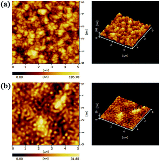
:![[thin space (1/6-em)]](https://www.rsc.org/images/entities/char_2009.gif) 1 for the ZnO sol–gel film and the ZnO sol–gel/TiO2 bilayered film, respectively, which may be responsible for the improved thermal stability of perovskite films on the bilayered ETLs to some extent. Moreover, it is obvious that the ratio of hydroxyls in the ZnO sol–gel is significantly lower than that in the ZnO NPs, and even comparable to that in ZnO NPs/TiO2 bilayered films. Therefore, we believe that the better thermal stability for perovskite films on the ZnO sol–gel films as compared to the ZnO-NP films can be, at least partly, ascribed to fewer hydroxyls on the surface of the ZnO sol–gel films. Fewer hydroxyls on the ZnO sol–gel film surface probably result from its relatively smooth surface where less molecularly water can be absorbed.22 Also, we employed FT-IR to investigate chemical groups in the ZnO-NP films and the ZnO sol–gel films. As shown in Fig. S3,† the peak associated to the stretching of hydroxyls around 3400 cm−1 in the ZnO sol–gel sample is obviously stronger than that in the ZnO NP-sample, which seems to be contradictory to the XPS results presented above. However, given that the ZnO sol–gel film is formed by polycondensation reaction and less crystalized (which can be supported by XRD results discussed above), much more hydroxyl groups should exist inside the ZnO sol–gel film than the ZnO-NP film. Moreover, FT-IR is a technique commonly used to probe bulk properties of materials rather than their surface properties which XPS is capable of characterizing. We believe that the inconsistency is understandable and the decomposition of perovskite is predominately caused by hydroxyl groups on the ZnO film surface rather than inside the film. In addition, to gain more insights into possible reasons for the stability difference between perovskite films on these two kinds of ZnO, their surface topography was further characterized via AFM measurements (Fig. 4). Consistent with the top-view SEM results, the root mean square (RMS) roughness of the ZnO-NP film (32.63 nm) is much higher than that of the ZnO sol–gel film (5.695 nm). The rougher surfaces of ZnO-NP films provide more contact area with perovskite, leading to the deteriorated thermal stability of perovksite.
1 for the ZnO sol–gel film and the ZnO sol–gel/TiO2 bilayered film, respectively, which may be responsible for the improved thermal stability of perovskite films on the bilayered ETLs to some extent. Moreover, it is obvious that the ratio of hydroxyls in the ZnO sol–gel is significantly lower than that in the ZnO NPs, and even comparable to that in ZnO NPs/TiO2 bilayered films. Therefore, we believe that the better thermal stability for perovskite films on the ZnO sol–gel films as compared to the ZnO-NP films can be, at least partly, ascribed to fewer hydroxyls on the surface of the ZnO sol–gel films. Fewer hydroxyls on the ZnO sol–gel film surface probably result from its relatively smooth surface where less molecularly water can be absorbed.22 Also, we employed FT-IR to investigate chemical groups in the ZnO-NP films and the ZnO sol–gel films. As shown in Fig. S3,† the peak associated to the stretching of hydroxyls around 3400 cm−1 in the ZnO sol–gel sample is obviously stronger than that in the ZnO NP-sample, which seems to be contradictory to the XPS results presented above. However, given that the ZnO sol–gel film is formed by polycondensation reaction and less crystalized (which can be supported by XRD results discussed above), much more hydroxyl groups should exist inside the ZnO sol–gel film than the ZnO-NP film. Moreover, FT-IR is a technique commonly used to probe bulk properties of materials rather than their surface properties which XPS is capable of characterizing. We believe that the inconsistency is understandable and the decomposition of perovskite is predominately caused by hydroxyl groups on the ZnO film surface rather than inside the film. In addition, to gain more insights into possible reasons for the stability difference between perovskite films on these two kinds of ZnO, their surface topography was further characterized via AFM measurements (Fig. 4). Consistent with the top-view SEM results, the root mean square (RMS) roughness of the ZnO-NP film (32.63 nm) is much higher than that of the ZnO sol–gel film (5.695 nm). The rougher surfaces of ZnO-NP films provide more contact area with perovskite, leading to the deteriorated thermal stability of perovksite.
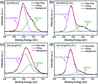 | ||
| Fig. 3 XPS spectra of (a) a ZnO-NP film, (b) a ZnO NPs/TiO2 bilayered film, (c) a ZnO sol–gel film, and (d) a ZnO sol–gel/TiO2 bilayered film. | ||
Fig. 5 shows the SEM images of perovskite films on these four different ETLs. It can be seen that the morphology of the perovskite film deposited on the ZnO-NP film is clearly different from that on the ZnO sol–gel film. The former is composed of bigger grains with size of around 200 nm and a few voids, which is probably induced by the release of gas byproducts from perovskite decomposition,23 whereas the latter is flat and dense, and made of smaller grains of about 100 nm. It is speculated that the different morphologies between these two samples is due to the occurrence of distinct nucleation and crystal growth processes caused by different underlying ETLs.24,25 The perovskite films on the ZnO NPs/TiO2 film and the ZnO sol–gel/TiO2 film have very similar surface morphology owing to the existence of the same underlying TiO2 layers.
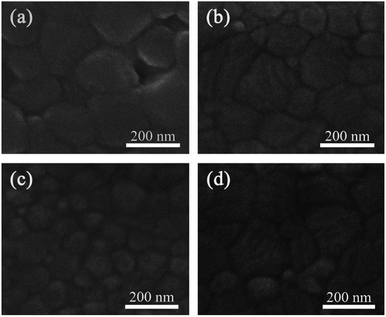 | ||
| Fig. 5 SEM images of perovskite films deposited on (a) a ZnO-NP film, (b) a ZnO NPs/TiO2 bilayered film, (c) a ZnO sol–gel film, and (d) a ZnO sol–gel/TiO2 bilayered film, respectively. | ||
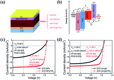
Using the perovskite films deposited on these four ETLs, we further fabricated PSCs with the structure of FTO/ETL/CH3NH3PbI3/spiro-OMeTAD/Au, as illustrated in Fig. 6(a), in order to investigate the effects of underlying ETLs on device performance and stability (the cross-sectional SEM image of a typical actual device is shown in Fig. S4†). These devices' schematic energy band diagram is shown in Fig. 6(b). The optimized thicknesses of the ZnO-NP films, ZnO sol–gel films, TiO2 capping layers, perovskite films, spiro-OMeTAD films and Au films are 50 nm, 50 nm, 60 nm, 450 nm, 190 nm and 60 nm, respectively. Statistics results of photovoltaic parameters, series resistance (Rs) and shunt resistance (Rsh) for PSCs fabricated on the ZnO-NP films, ZnO NPs/TiO2 bilayered films, ZnO sol–gel films and ZnO sol–gel/TiO2 bilayered films are tabulated in Table 1. The typical current density–voltage (J–V) characteristics of the PSCs based on these four ETLs under AM 1.5G 100 mW cm−2 simulated solar light are shown in Fig. 6(c) and (d). The device with the ZnO NP-ETL, as shown in Fig. 6(c), exhibits a poor PCE of 3.56% with an open circuit voltage (Voc) of 0.98 V, a short-circuit current density (Jsc) of 9.94 mA cm−2, and a fill factor (FF) of 36.50%, while the device containing the ZnO NPs/TiO2 bilayered ETL yields a dramatically enhanced PCE of 15.0% with a Voc of 1.06 V, a Jsc of 19.1 mA cm−2, and a FF of 73.9%. Also, it can be clearly seen from Fig. 6(d) that the device based on the ZnO sol–gel/TiO2 bilayered ETL shows a high PCE of 14.55% with a Voc of 1.08 V, a Jsc of 18.11 mA cm−2, and a FF of 74.38%. In contrast, a decent PCE of 9.03% can only be achieved for the device with the ZnO sol–gel single-layer ETL due to the reduced Jsc (15.90 mA cm−2) and FF (52.58%). We note that, as shown in Fig. S5 and Table S1,† the hysteresis of these devices based on low-temperature ETLs is serious probably due to the existence of a large number of defects in these ETL materials.26 But then, devices based on the ZnO/TiO2 bilayered ETLs show less hysteresis than the corresponding ZnO-only devices.
| ETL | Voc (V) | Jsc (mA cm−2) | FF (%) | PCE (%) | Rs/Ohm | Rsh/Ohm |
|---|---|---|---|---|---|---|
| ZnO NPs | 0.94 ± 0.03 | 9.40 ± 0.68 | 35.46 ± 2.86 | 3.12 ± 0.15 | 2086 ± 172 | 10![[thin space (1/6-em)]](https://www.rsc.org/images/entities/char_2009.gif) 948 ± 1333 948 ± 1333 |
| ZnO NPs/TiO2 | 1.06 ± 0.007 | 18.89 ± 0.37 | 71.95 ± 2.63 | 14.44 ± 0.43 | 263 ± 15 | 53![[thin space (1/6-em)]](https://www.rsc.org/images/entities/char_2009.gif) 427 ± 5253 427 ± 5253 |
| ZnO sol–gel | 1.06 ± 0.01 | 15.53 ± 0.22 | 51.50 ± 0.98 | 8.48 ± 0.27 | 679 ± 41 | 18![[thin space (1/6-em)]](https://www.rsc.org/images/entities/char_2009.gif) 807 ± 1452 807 ± 1452 |
| ZnO sol–gel/TiO2 | 1.06 ± 0.008 | 18.04 ± 0.13 | 74.31 ± 0.32 | 14.26 ± 0.16 | 250 ± 15 | 49![[thin space (1/6-em)]](https://www.rsc.org/images/entities/char_2009.gif) 756 ± 4490 756 ± 4490 |
To elucidate the influence of these underlying ETLs on perovskite properties and device performance, a variety of structural, optical and electrical measurements on the perovskite films and devices were further conducted. For the perovskite films deposited on the ZnO NP-ETL and the ZnO NPs/TiO2 bilayered ETL, XRD patterns [Fig. 7(a)] show that, as expected, there is a characteristic diffraction peak of PbI2 (001) at around 12.8° for the perovskite film on the ZnO NP-ETL, suggesting a fast decomposition of MAPbI3 into PbI2 in the course of device fabrication. However, the peak is missing for the perovskite film on the ZnO NPs/TiO2 bilayered ETL, which indicates that the decomposition of perovskite on the ZnO NPs/TiO2 bilayered film has been effectively suppressed. This is consistent with the results of the accelerated degradation experiment shown in Fig. 2. The absorbance spectra of both perovskite films are shown in Fig. 8(a). It can be seen that the absorption intensity of the perovskite film on the ZnO NP-ETL is slightly lower than that on the ZnO/TiO2 bilayered ETL, and an shoulder around 498 nm only occurs in the former's absorption spectrum, further indicating the decomposition of perovskite on the ZnO NP-ETL into PbI2.27 The degradation of perovskite does not have too much influence on Voc, but reduces Jsc and FF remarkably, thereby adversely affecting the final device performance. It could be ascribed to the increased series resistance and associated recombination as a consequence of inhomogeneous degradation of the perovskite film.28 As tabulated in Table 1, the devices containing these ZnO NPs/TiO2 bilayered ETLs have much lower series resistance (Rs) and remarkably higher shunt resistance (Rsh) calculated from J–V curves than the cells based on those ZnO NP-ETLs.
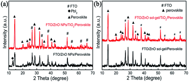 | ||
| Fig. 7 XRD patterns of perovskite films deposited (a) on a ZnO-NP film and a ZnO NPs/TiO2 bilayered film; (b) on a ZnO sol–gel film and a ZnO sol–gel/TiO2 bilayered film. | ||
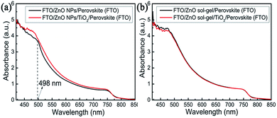 | ||
| Fig. 8 Absorbance spectra of perovskite films deposited (a) on a ZnO NP-film and a ZnO NPs/TiO2 bilayered film; (b) on a ZnO sol–gel film and a ZnO sol–gel/TiO2 bilayered film. | ||
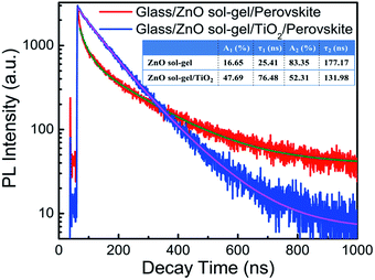
For the perovskite films deposited on the ZnO sol–gel ETL and the ZnO sol–gel/TiO2 bilayered ETL, as shown in Fig. 7(b), no characteristic diffraction peaks of PbI2 can be detected. Moreover, the absorption intensity of perovskite on the ZnO sol–gel ETL is almost the same as that on the ZnO sol–gel/TiO2 bilayered ETL [Fig. 8(b)]. Therefore, the enhanced performance for devices on the ZnO sol–gel/TiO2 bilayered films may be not mainly due to the suppressed decomposition of perovskite, though they have lower Rs and higher Rsh compared to those on the ZnO sol–gel ETLs, as tabulated in Table 1. To further investigate possible reasons for the improved efficiency, time-resolved photoluminescence (TRPL) measurements of perovskite films deposited on the ZnO sol–gel film and the ZnO sol–gel/TiO2 bilayered film were performed and displayed in Fig. 9. The TRPL spectra of the perovskite films on both ETLs show bi-exponential decays with fast (τ1) and slow (τ2) components, and the resulting decay lifetimes and decay amplitudes (Ai) are listed in the inset of Fig. 9. It is reported that τ1 is a decay component closely related to non-radiative recombination by defects (e.g. surface traps near grain boundaries), while τ2 is a component of radiative recombination from bulk perovskite.17,29 As shown in Fig. 9 and its inset, on one hand, the perovskite on the ZnO sol–gel/TiO2 bilayered film has a much longer lifetime τ1 compared to the perovskite deposited on the ZnO sol–gel film, suggesting it has fewer traps near grain boundaries. This is in consistence with the results deduced from the SEM images (Fig. 5) that the perovskite on the ZnO sol–gel film has more grain boundaries due to their smaller grain size. On the other hand, perovskite on the ZnO sol–gel/TiO2 bilayered film has a much shorter lifetime τ2 compared to perovskite deposited on the ZnO sol–gel film, implying that the electron transfer from perovskite to the ZnO sol–gel/TiO2 bilayered film is faster than the ZnO sol–gel film. According to the equation τave = ∑Aiτi2/∑Aiτi, the estimated average carrier lifetimes (τave) in these perovskite films deposited on the ZnO sol–gel and ZnO sol–gel/TiO2 films are 172.94 ns and 112.79 ns, respectively. The more efficient carrier extraction between perovskite and the ZnO sol–gel/TiO2 bilayer-ETL is further confirmed by the weaker steady-state PL in comparison with perovskite on the ZnO sol–gel film, as shown in Fig. S6.† The more efficient carrier extraction in the ZnO sol–gel/TiO2 bilayer-based device results in a higher Jsc.30,31 The higher FF for the ZnO sol–gel/TiO2 bilayer-ETL device can be ascribed to its lower Rs and higher Rsh, as shown in Table 1.31,32 In addition, although the conductivity of the ZnO sol–gel film is much lower than that of the ZnO-NP film (Fig. S7†), it is evident that the device performance based on the ZnO sol–gel ETL is far superior to the device based on the ZnO NP-ETL, which can be attributed to the fact that perovskite on the ZnO sol–gel films is much more stable. As shown in Fig. S8,† the more stable perovskite film on the ZnO sol–gel film behaves better in light harvesting compared to that on the ZnO-NP film. As mentioned above, the appearance of a shoulder at around 498 nm for the perovskite/ZnO-NP film indicates the partial decomposition of perovskite into PbI2.27
Also, we fabricated perovskite solar cells based on low-temperature TiO2-only ETLs to see if the performance enhancement just comes from the usage of TiO2. The typical J–V curve of the TiO2-only device is shown in Fig. S9.† When comparing the TiO2-only device with those ZnO/TiO2 devices, we can find that the former has a lower PCE than its bi-ETL counterparts mainly due to the reduced Voc and FF. Therefore, we believe that the enhanced device performance after the introduction of TiO2 is not only due to the fact that it may prevent the quick decomposition of perovskite, but also due to its synergistic effect with ZnO. For these ZnO/TiO2 bilayered ETLs, the conduction band of TiO2 is slightly higher than that of ZnO, which not only facilitates the electron injection from perovskite into ETL but also prevents the back electron transfer from ETL to perovksite.19 Or, from another perspective, a n+–n heterojunction might be formed at the ZnO/TiO2 interface, where the induced built-in electrical field is beneficial to the suppression of interfacial charge recombination.33 The reduced charge recombination at the perovskite/bilayered ETL interface is beneficial to increasing FF and Voc.19,34
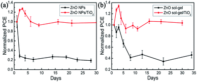
To evaluate device stability, unencapsulated devices fabricated on these four ETLs were stored in ambient environment (temperature: ∼20 °C; relative humidity: ∼20%) and tested under standard one sun illumination every few days. The plots of the normalized average PCEs as a function of storage time are shown in Fig. 10(a) and (b). The devices with the ZnO NP-ETLs drastically degraded and lost 75% of their initial efficiency merely within two days, showing considerably poor device stability. In contrast, the average efficiency of devices with the ZnO NPs/TiO2 bilayer-ETLs increased first and then decreased, but nearly 100% of their initial efficiency was still retained even after thirty days, exhibiting much higher device stability. The initial device performance evolution was simultaneously affected by two factors: spiro-OMeTAD oxidation and perovskite decomposition. The former can increase device efficiency, while the latter will degrade device performance. We note that the initial efficiency enhancement of these devices based on the bilayered ETLs might be attributed to the dominant spiro-OMeTAD oxidation, while the monotonic efficiency decline with the storage time for those devices based on the ZnO NP-ETLs results from their serious and predominant perovskite decomposition. Likewise, the average efficiency of devices with the ZnO sol–gel ETLs was only 40% of their initial value after eight days. However, the average efficiency of devices with the ZnO sol–gel/TiO2 bilayered ETLs could remain their initial efficiency even after thirty days. Therefore, the ZnO/TiO2 bilayer-ETLs reported in the work can not only significantly enhance device performance, but also effectively improve the device stability of ZnO-based PSCs.
Conclusions
The ZnO/TiO2 bilayered films prepared by solution processes at low-temperature have been successfully employed as electron transport layers in MAPbI3-based perovskite solar cells. The devices based on these low-temperature ZnO/TiO2 bilayered ETLs exhibit not only high photovoltaic performance but also extraordinarily good stability compared with those based on ZnO single-layer ETLs. Moreover, it has been found that the perovskite films prepared on the ZnO sol–gel films are much superior to those deposited on the ZnO-NP films in both film stability and device performance, which can be ascribed to less surface hydroxyl groups and much smoother surface morphology in the ZnO sol–gel films. Our results suggest that the ZnO/TiO2 bilayered films and even ZnO sol–gel films can be good ETL candidates for low-temperature PSCs, and pave the way for the fabrication of efficient and stable PSCs on flexible substrates.Conflicts of interest
There are no conflicts of interest to declare.Acknowledgements
This work was supported by the Basic Research Project of Shanxi Province (No. 201701D221079), the National Natural Science Foundation of China (No. 61475110), CAS Key Laboratory of Renewable Energy (No. Y807k31001) and the Youth Foundation of Taiyuan University of Technology (2015QN102). It was also partially supported by the National Natural Science Foundation of China (21471111, 61404089, 61504090, and 61604104), the National Key Research and Development Program of China (2016YFB0401803), the Basic Research Projects of Shanxi Province (2015021103 and 201601D202029), the Shanxi Provincial Key Innovative Research Team in Science and Technology (201605D131045-10), and the Platform and Base Special Project of Shanxi (201605D131038).Notes and references
- A. Kojima, K. Teshima, Y. Shirai and T. Miyasaka, J. Am. Chem. Soc., 2009, 131, 6050–6051 CrossRef PubMed.
- http://www.nrel.gov/pv/assets/images/efficiency_chart.jpg (Rev. 12-15-2017).
- C. C. Stoumpos, C. D. Malliakas and M. G. Kanatzidis, Inorg. Chem., 2013, 52, 9019–9038 CrossRef PubMed.
- D. H. Fabini, J. G. Labram, A. J. Lehner, J. S. Bechtel, H. A. Evans, d. V. A. Van, F. Wudl, M. L. Chabinyc and R. Seshadri, Inorg. Chem., 2017, 56, 11–25 CrossRef PubMed.
- S. D. Stranks, G. E. Eperon, G. Grancini, C. Menelaou, M. J. P. Alcocer, T. Leijtens, L. M. Herz, A. Petrozza and H. J. Snaith, Science, 2013, 342, 341–344 CrossRef PubMed.
- E. J. Juarez-Perez, M. Wuβler, F. Fabregat-Santiago, K. Lakus-Wollny, E. Mankel, T. Mayer, W. Jaegermann and I. Mora-Sero, J. Phys. Chem. Lett., 2014, 5, 680–685 CrossRef PubMed.
- Q. Hu, J. Wu, C. Jiang, T. Liu, X. Que, R. Zhu and Q. Gong, ACS Nano, 2014, 8, 10161–10167 CrossRef PubMed.
- D. Liu and T. L. Kelly, Nat. Photonics, 2014, 8, 133–138 CrossRef.
- J. T. Wang, J. M. Ball, E. M. Barea, A. Abate, J. A. Alexander-webber, J. Huang, M. Saliba, I. Mora-sero, J. Bisquert, H. J. Snaith and R. J. Nicholas, Nano Lett., 2013, 14, 724–730 CrossRef PubMed.
- Q. Jiang, L. Zhang, H. Wang, X. Yang, J. Meng, H. Liu, Z. Yin, J. Wu, X. Zhang and J. You, Nat. Energy, 2016, 2, 16177 CrossRef.
- Q. Liu, M. C. Qin, W. J. Ke, X. L. Zheng, Z. Chen, P. L. Qin, L. B. Xiong, H. W. Lei, J. W. Wan, J. Wen, G. Yang, J. J. Ma, Z. Y. Zhang and G. J. Fang, Adv. Funct. Mater., 2016, 26, 6069–6075 CrossRef.
- T. Pauporté and I. Jirka, Electrochim. Acta, 2009, 54, 7558–7564 CrossRef.
- J. Song, W. Hu, X. F. Wang, G. Chen, W. Tian and T. Miyasaka, J. Mater. Chem. A, 2016, 4, 8435–8443 RSC.
- M. A. Mahmud, N. K. Elumalai, M. B. Upama, D. Wang, K. H. Chan, M. Wright, C. Xu,, F. Haque and A. Uddin, Sol. Energy Mater. Sol. Cells, 2017, 159, 251–264 CrossRef.
- Y. Cheng, Q. D. Yang, J. Xiao, Q. Xue, H. W. Li, Z. Guan, H. L. Yip and S. W. Tsang, ACS Appl. Mater. Interfaces, 2015, 7, 19986–19993 CrossRef PubMed.
- J. Yang, B. D. Siempelkamp, E. Mosconi, F. D. Angelis and T. L. Kelly, Chem. Mater., 2015, 27, 4229–4236 CrossRef.
- Z. L. Tseng, C. H. Chiang, S. H. Chang and C. G. Wu, Nano Energy, 2016, 28, 311–318 CrossRef.
- J. Song, E. Zheng, L. Liu, X. F. Wang, G. Chen, W. Tian and T. Miyasaka, ChemSusChem, 2016, 9, 1–9 CrossRef.
- P. Chen, X. Yin, M. Que, Y. Yang and W. Que, RSC Adv., 2016, 6, 57996–58002 RSC.
- Y. Sun, J. H. Seo, C. J. Takacs, J. Seifter and A. J. Heeger, Adv. Mater., 2011, 23, 1679–1683 CrossRef PubMed.
- N. Ahn, D. Y. Son, I. H. Jang, S. M. Kang, M. Choi and N. G. Park, J. Am. Chem. Soc., 2015, 137, 8696–8699 CrossRef PubMed.
- K. Yadav, B. R. Mehta, S. Bhattacharya and J. P. Singh, Sci. Rep., 2016, 6, 35073 CrossRef PubMed.
- G. S. Han, H. W. Shim, S. Lee, M. L. Duff and J. K. Lee, ChemSusChem, 2017, 10, 2425–2430 CrossRef PubMed.
- J. Zhang and T. Pauporté, J. Phys. Chem. C, 2015, 119, 14919–14928 CrossRef.
- C. Bi, Q. Wang, Y. Shao, Y. Yuan, Z. Xiao and J. Huang, Nat. Commun., 2015, 6, 7747 CrossRef PubMed.
- X. Cao, L. Zhi, Y. Li, X. Cui, L. Ci, K. Ding and J. Wei, RSC Adv., 2017, 7, 49144–49150 RSC.
- J. Zhang, G. Zhai, W. Gao, C. Zhang, Z. Shao, F. Mei, J. Zhang, Y. Yang, X. Liu and B. Xu, J. Mater. Chem. A, 2017, 5, 4190–4198 RSC.
- B. Conings, J. Drijkoningen, N. Gauquelin, A. Babayigit, J. D'Haen, L. D'Olieslaeger, A. Ethirajan, J. Verbeeck, J. Manca and E. Mosconi, Adv. Energy Mater., 2015, 5, 1500477 CrossRef.
- D. Y. Son, J. W. Lee, Y. J. Choi, I. H. Jang, S. Lee, P. J. Yoo, H. Shin, N. Ahn, M. Choi, D. Kim and N. G. Park, Nat. Energy, 2016, 1, 16081 CrossRef.
- Q. Dong, Y. Shi, K. Wang, Y. Li, S. Wang, H. Zhang, Y. Xing, Y. Du, X. Bai and T. Ma, J. Phys. Chem. C, 2015, 119, 10212–10217 CrossRef.
- B. X. Chen, H. S. Rao, W. G. Li, Y. F. Xu, H. Y. Chen, D. B. Kuang and C. Y. Su, J. Mater. Chem. A, 2016, 4, 5647–5653 RSC.
- J. Wang, M. Qin, H. Tao, W. Ke, Z. Chen, J. Wan, P. Qin, L. Xiong, H. Lei, H. Yu and G. Fang, Appl. Phys. Lett., 2015, 106, 121104 CrossRef.
- M. Law, L. E. Greene, A. Radenovic, T. Kuykendall, J. Liphardt and P. Yang, J. Phys. Chem. B, 2006, 110, 22652–22663 CrossRef PubMed.
- J. Xu, Z. Chen, J. A. Zapien, C. S. Lee and W. Zhang, Adv. Mater., 2014, 26, 5337–5367 CrossRef PubMed.
Footnote |
| † Electronic supplementary information (ESI) available: [Fig. S1–Fig. S9]. See DOI: 10.1039/c8ra03162b |
| This journal is © The Royal Society of Chemistry 2018 |


