 Open Access Article
Theoretical insights into the reaction mechanisms between 2,3,7,8-tetrachlorodibenzofuran and the methylidyne radical†
Wenjing Wei,
Weihua Wang*,
Kaining Xu,
Wenling Feng,
Xiaoping Li and
Ping Li *
*
Key Laboratory of Life-Organic Analysis, School of Chemistry and Chemical Engineering, Qufu Normal University, Qufu, 273165, P. R. China. E-mail: lignip@163.com; wwh78@163.com
First published on 8th June 2018
Abstract
To explore the potential role of the methylidyne radical (CH) in the transformation of 2,3,7,8-tetrachlorodibenzofuran (TCDF), in this study, the detailed reaction mechanisms between TCDF and CH radical have been systematically investigated employing the B3LYP method of density functional theory (DFT) in combination with the atoms in molecules (AIM) theory and ab initio molecular dynamics. It was found that the title reaction is a multi-channel reaction, i.e., the CH radical can attack the C–X (X = C, Cl, H, O) bonds of TCDF via the insertion modes, resulting in the formation of 13 products. Thermodynamically, the whole reaction processes are exothermic and spontaneous since all the enthalpy and Gibbs free energy changes are negative values in the formation processes. Moreover, the thermodynamic stability of the products is controlled by the distribution of the single unpaired electron. Kinetically, the most favorable reaction channel is the insertion of the CH radical into the C–C bond except for the C atoms attached to the chlorine atom. Moreover, the dominant products have been further confirmed by the molecular dynamics. Meanwhile, the IR spectra and hyperfine coupling constants of the dominant products have been investigated to provide helpful information for their identification experimentally. In addition, the reactivity of the CH radical toward the F- and Br-substituted TCDFs has also been investigated. Expectedly, the present findings can enable us to better understand the reactivity of the CH radical toward organic pollutants analogous to TCDF in the atmosphere.
1. Introduction
Nowadays, the control, reduction, and conversion of persistent organic pollutants (POPs) have become important global environmental problems because POPs have posed a serious threat to human health and the ecological environment. As representative POPs, polychlorinated dibenzofurans (PCDFs) have been studied extensively due to their highly toxicological effects (e.g., dermal toxicity, immunotoxicity, and carcinogenicity, etc.) and widespread occurrence in the environment. It is well recognized that the major sources of PCDFs are incineration and thermal decomposition of waste materials involving chlorine as well as natural combustion processes (e.g., volcanic activity). Up to now, many studies have been carried out to gain a better understanding of the formation1–8 and degradation9–25 of PCDFs experimentally and theoretically. Especially, for the degradation of PCDFs, many methods have been proposed, such as microbial degradation, photocatalytic decomposition, and high temperature degradation, etc. Obviously, the unique stable structures of PCDFs limit their degradation in practice. Actually, only a few active free radicals, such as OH, NO3, and H radicals, can react with PCDFs. Thus, it is necessary to seek new species which can react with PCDFs so as to provide useful clues to the transformation and degradation of PCDFs for experiments.As one of the most reactive radical species, the methylidyne radical (CH) is well known to be of great importance in various fields, such as combustion chemistry, dense interstellar clouds, and planetary atmospheres. Its extreme reactivity arises from the presence of one singly occupied and one vacant non-bonding molecular orbital localized on the carbon atom.37 Therefore, CH radical can react with most species ranging from small alkanes,28–31 alkene,28,32–38 alkyne,28,33,37–39 pyrrole,41 acrolein42 to large polycyclic aromatic hydrocarbons like anthracene (C14H10),43 providing an alternative way to synthesize long-chain or ring-expanded hydrocarbons and complex organic molecules. For example, CH radical can react with pyrrole to produce the ring expansion product pyridine,41 where CH radical can be readily prepared experimentally via the photolysis of bromoform at room temperature. The cyclic versus linear isomers produced by the reaction of the CH radical with small unsaturated hydrocarbons involving ethylene, acetylene, allene, and methylacetylene have been investigated experimentally and theoretically.45 Recently, the reactions of the CH radical with C3H8, CH4, C3H6, and C3H4 have been systematically investigated theoretically by Ribeiro et al.30–33 providing new insights into the detailed reaction mechanisms for the CH radical chemistry. As a general rule, more and more studies suggest that the reactions of the CH radical with other species can occur barrierlessly44 and are high exothermicity.40
Inspired by the highly reactive CH radical in the above studies26–47 as well as the specific geometry of PCDFs containing the different types of C–X (X = C, Cl, H, O) bonds, we wonder if PCDFs can react with CH radical so as to change their geometries and even properties. If so, what are the detailed reaction mechanisms and the dominant reaction products? Moreover, how about the properties of the dominant products, such as IR and hyperfine coupling constants (hfcc's)? In addition, do the PCDFs derivatives, such as F- and Br- substituted species, also have similar reactivity with CH radical? Obviously, the clarification of the above questions will enable us to have a better understanding of the potential reactivity of CH radical in the atmosphere.
Unfortunately, the above questions remain unclear to the best of our knowledge. Therefore, in this study, taking the 2,3,7,8-tetrachlorodibenzofuran (TCDF) as model compound of PCDFs, its reaction with CH radical has been systematically investigated employing the density functional theory (DFT) method in combination with ab initio molecular dynamics. As a result, the detailed reaction mechanisms, thermodynamic information, and kinetic data for the title reaction have been clarified at the molecular level. Hopefully, the present results not only can clarify the potential reactivity of the highly reactive CH radical with TCDF and provide new insights into the transformation and degradation of TCDF in the atmosphere, but also can provide helpful information to promote the progress of the relevant experiments.
2. Computational methods
Nowadays, the density functional theory (DFT) method has been widely applied in computational chemistry since its reliability and efficiency in predicting the geometries and properties has been verified by a lot of studies including the CH radical.30–34,46–57 Therefore, all the species in the whole reactions have been fully optimized at the B3LYP/6-311++G** level of theory. Subsequently, vibrational frequency analysis has been performed at the same level of theory to identify the nature of the optimized structures. Moreover, intrinsic reaction coordinate (IRC) calculations were performed to further verify that the calculated transition states indeed connected the reactants and products.58,59 In addition, single-point energy calculations have been performed at the B3LYP/AUG-cc-pVTZ level of theory to further refine the energy parameters for the formation of the initial intermediates and the main reaction pathways. As shown in Tables 1 and 2, both levels of theory can give consistent results with each other. For the sake of consistency, the results at the B3LYP/6-311++G** level of theory have been discussed below if not noted otherwise, where all the energy parameters are corrected by the zero-point vibrational energy (ZPVE). All the Cartesian coordinates of the optimized species and the IRC plots for all the pathways have been given in the ESI† for reference.| Intermediates | ΔErela | ΔH | ΔG |
|---|---|---|---|
| a All the energy parameters are relative to the initial reactants. All the units are in kcal mol−1. The data before and after the slash refer to the results of the F- and Br-substituted cases, respectively. The data in bracket refer to the results at the B3LYP/AUG-cc-pVTZ level of theory including the ZPVE corrections at the B3LYP/6-311++G** level of theory. | |||
| IM1 | −53.74[−52.88] | −54.98[−54.12] | −44.99[−44.14] |
| (−53.33/−54.86) | (−54.59/−56.08) | (−44.55/−46.19) | |
| IM2 | −53.87[−52.95] | −55.12[−54.20] | −45.10[−44.18] |
| (−53.31/−55.13) | (−54.59/−56.37) | (−44.50/−46.43) | |
| IM3 | −43.71[−43.36] | −44.89[−44.54] | −35.06[−34.71] |
| (−41.33/−44.23) | (−42.47/−45.44) | (−32.75/−35.58) | |
| IM4 | −35.71[−34.95] | −36.98[−36.22] | −26.89[−26.13] |
| (−36.83/−35.60) | (−38.12/−36.89) | (−27.94/−26.81) | |
| IM5 | −37.10[−36.37] | −38.32[−37.60] | −28.32[−27.59] |
| (−38.20/−37.01) | (−39.42/−38.25) | (−29.39/−28.27) | |
| IM6 | −45.08[−44.69] | −46.26[−45.87] | −36.43[−36.04] |
| (−43.10/−45.47) | (−44.24/−46.67) | (−34.48/−36.80) | |
| IM7 | −52.65[−51.75] | −53.89[−52.98] | −43.90[−43.00] |
| (−52.07/−53.88) | (−53.32/−55.11) | (−43.31/−45.19) | |
| IM8 | −52.67[−51.71] | −53.91[−52.96] | −43.89[−42.94] |
| (−51.89/−54.00) | (−53.16/−55.24) | (−43.11/−45.29) | |
| IM9 | −8.35[−10.64] | −8.88[−11.17] | −0.58[−2.87] |
| IM10 | −8.78[−10.92] | −9.33[−11.47] | −0.98[−3.13] |
| Reactions | TSs | ΔErela | ΔH | ΔG | ||
|---|---|---|---|---|---|---|
| a All the units are in kcal mol−1. The direction from left to right is defined as the forward reaction. The data in parentheses refer to the results without considering the ZPVE corrections. The data before and after the slash refer to the results of the F- and Br-substituted cases, respectively. The data in bracket refer to the results using the AUG-cc-pVTZ basis set. | ||||||
| IM1 ⇌ IM2 | TS1 | −53.49 | 0.25 | 0.38 | −0.14 | −0.11 |
| IM1 ⇌ P1 | TS2 | −52.22[−51.64] | 1.52[1.25] | 49.52[50.74] | −48.01[−49.51] | −48.18[−49.68] |
| −52.12/−53.37 | 1.21/1.49 | 52.52/47.73 | −51.26/−46.24 | −51.50/−46.56 | ||
| IM2 ⇌ P1 | TS3 | −51.10[−50.35] | 2.77[2.60] | 50.64[52.03] | −47.87[−49.44] | −48.07[−49.64] |
| −49.49/−52.44 | 3.82/2.70 | 55.15/48.66 | −51.26/−45.95 | −51.55/−46.32 | ||
| IM3 ⇌ P1 | TS4 | −43.96 | −0.25(0.28) | 57.77 | −58.10 | −58.11 |
| [−43.61] | [−0.25(0.28)] | [58.77] | [−59.09] | [−59.11] | ||
| −41.66/−44.54 | −0.33(0.06) | 62.98/56.56 | −63.38/−56.89 | −63.30/−57.17 | ||
| /−0.31(0.19) | ||||||
| IM10 ⇌ IM2 | TS5 | −0.95 | 7.83 | 52.92 | −45.79 | −44.12 |
| IM4 ⇌ IM5 | TS6 | −35.07 | 0.64 | 2.03 | −1.34 | −1.43 |
| IM4 ⇌ P2 | TS7 | −34.53 | 1.18 | 2.41 | −1.17 | −1.14 |
| −35.45/−34.51 | 1.38/1.09 | 2.20/2.66 | −0.73/−1.51 | −0.80/−1.43 | ||
| IM5 ⇌ P3 | TS8 | −37.24 | −0.14(0.14) | 3.47 | −3.75 | −3.33 |
| [−36.54] | [−0.17(0.11)] | [3.49] | [−3.80] | [−3.38] | ||
| −38.37/−37.12 | −0.17(0.09) | 4.15/3.57 | −4.51/−3.81 | −4.01/−3.36 | ||
| /−0.12(0.17) | ||||||
| P2 ⇌ P3 | TS9 | −37.25 | −0.30(0.32) | 3.46 | −3.92 | −3.62 |
| −38.05/−37.45 | −0.40(0.13) | 4.47/3.24 | −5.08/−3.66 | −4.67/−3.38 | ||
| /−0.28(0.07) | ||||||
| IM4 ⇌ P4 | TS10 | −1.04[−1.00] | 34.67[33.95] | 99.89[100.46] | −65.22[−66.50] | −65.62[−66.91] |
| IM6 ⇌ P4 | TS11 | −45.05[−44.68] | 0.03[0.01] | 55.88[56.78] | −55.94[−56.85] | −56.08[−56.99] |
| −43.44/−45.50 | −0.35(0.21) | 60.95/54.73 | −61.39/−54.80 | −61.33/−55.66 | ||
| /−0.03(0.87) | ||||||
| IM7 ⇌ IM8 | TS12 | −52.31 | 0.34 | 0.35 | −0.03 | 0.01 |
| IM7 ⇌ P4 | TS13 | −51.01[−50.37] | 1.64[1.37] | 49.93[51.09] | −48.32[−49.74] | −48.61[−50.04] |
| −50.85/−52.23 | 1.22/1.65 | 53.54/48.00 | −52.31/−46.36 | −52.50/−47.27 | ||
| IM8 ⇌ P4 | TS14 | −49.48[−48.75] | 3.19[2.97] | 51.46[52.71] | −48.29[−49.77] | −48.62[−50.09] |
| −47.85/−50.97 | 4.04/3.03 | 56.54/49.26 | −52.48/−46.23 | −52.70/−47.17 | ||
| IM9 ⇌ IM8 | TS15 | −0.61 | 7.73 | 52.06 | −45.03 | −43.32 |
| IM7 ⇌ P5 | TS16 | −1.72 | 50.93 | 104.23 | −53.31 | −53.40 |
| P1 ⇌ P6 | TS17 | 27.74 | 129.47 | 147.52 | −18.16 | −17.74 |
| IM9 ⇌ P7 | TS18 | 4.02 | 12.37 | 112.07 | −100.38 | −99.10 |
| IM9 ⇌ P8 | TS19 | 4.16 | 12.51 | 118.10 | −106.31 | −104.75 |
| P7 ⇌ P8 | TS20 | −101.54 | 6.51 | 12.40 | −5.94 | −5.64 |
| P5 ⇌ P7 | TS21 | −22.06 | 83.89 | 85.99 | −2.05 | −2.38 |
| P5 ⇌ P8 | TS22 | −22.14 | 83.82 | 91.80 | −7.99 | −8.02 |
| IM8 ⇌ P8 | TS23 | −25.31 | 27.36 | 88.62 | −61.28 | −61.43 |
| IM9 ⇌ IM10 | TS24 | −0.99 | 7.36 | 7.79 | −0.45 | −0.41 |
| IM10 ⇌ P9 | TS25 | 4.86 | 13.64 | 111.62 | −98.62 | −97.48 |
| IM10 ⇌ P10 | TS26 | 5.16 | 13.94 | 117.79 | −104.54 | −103.04 |
| P9 ⇌ P10 | TS27 | −101.81 | 4.96 | 10.82 | −5.93 | −5.56 |
| IM6 ⇌ P11 | TS28 | −0.81 | 44.27 | 108.67 | −64.44 | −64.15 |
| P1 ⇌ P12 | TS29 | −14.23 | 87.51 | 94.71 | −7.16 | −6.92 |
| P4 ⇌ P13 | TS30 | −5.48 | 95.46 | 107.73 | −12.30 | −11.96 |
To clarify the structural features and the nature of the interatomic interactions for the initial intermediates and products, atoms in molecules (AIM) theory was employed on the basis of the optimized structures. In the AIM analyses, the interatomic interaction is indicated by the presence of a bond critical point (BCP). The corresponding strength can be estimated from the magnitude of the electron density (ρbcp) at the BCP. Similarly, the ring structures can be confirmed by the existence of a ring critical point (RCP). Additionally, the nature of the interatomic interaction can be predicted from the topological parameters at the BCP, such as the Laplacian (∇2ρbcp) and energy density (Hbcp). For example, the interatomic interactions are characterized by the covalent bonds (shared interaction) and the H-bonds as well as van der Waals interactions (closed-shell interaction) if ∇2ρbcp < 0 and ∇2ρbcp > 0, respectively. In addition, it was also reported that the interatomic interactions should be partially covalent if ∇2ρbcp > 0 and Hbcp < 0.60,61
To better confirm the presence of the non-covalent interactions in the selected products, the reduced density gradient (RDG) analysis was performed on the basis of the optimized structures. In this method, the different weak interactions can be intuitively illustrated using different colors in real space.62
To further clarify the interconversion among the initial intermediates and the formation processes of the products, ab initio molecular dynamics has been carried out at the B3LYP/6-311G** level of theory using the Atom Centered Density Matrix Propagation (ADMP) approach based on the optimized initial intermediates.63–65 Here, the dynamics calculations were performed with NVT ensemble at 298.15 K and the total simulation time is 1.0 ps with a time stepsize of 0.5 fs.
All the calculations have been performed using Gaussian 09 program.66
3. Results and discussion
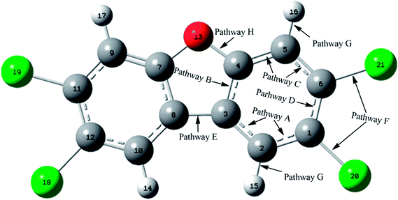
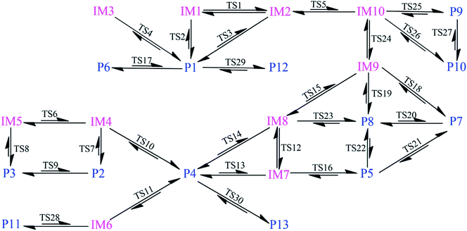
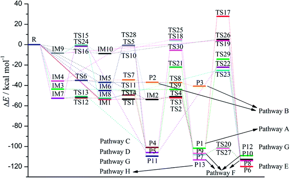
As shown in Fig. 1, the reaction of CH radical with TCDF is a multi-channel reaction via the insertion mode. In details, the whole reaction can be divided into four categories according to the type of the inserted bonds, i.e., the C–C (Pathways A–E), C–Cl (Pathway F), C–H (Pathway G), and C–O bond (Pathway H), respectively.As shown in Fig. 2, as the first step of the whole reaction, ten initial intermediates named as IM1–IM10 have been located barrierlessly, where the corresponding thermodynamic data have been summarized in Table 1. Obviously, the formation processes of them are spontaneous and strongly exothermic reactions except for IM9 and IM10, which can be reflected from the negative values of the enthalpy and Gibbs free energy changes (ΔH and ΔG). As for the formation of IM9 and IM10, small values have been observed for the ΔH and ΔG, implying the unfavorable formation of them thermodynamically. Subsequently, thirteen products P1–P13 and thirty transition states TS1–TS30 have been located in the interconversion processes among intermediates and products, where the relevant thermodynamic parameters and the energy barriers for the interconversion processes have been summarized in Table 2. For the sake of simplicity, the interconversion relationship among the initial intermediates, transition states, and products have been illustrated in Fig. 3. Moreover, the whole reaction profiles for the title reaction have been shown in Fig. 4.
 | ||
| Fig. 2 The optimized initial intermediates (IM), transition states (TS), and products in the reaction of TCDF with CH radical. | ||
3.1 Reaction pathways and the interconversions among intermediates
As shown in Fig. 5, many ring critical points have been observed in the initial intermediates and products except for IM9 and IM10, suggesting that additional ring structures have been formed for TCDF when the CH radical is introduced. Moreover, as presented in Table 3, the negative values of ∇2ρbcp at the BCPs suggests that the formed bonds between the CH radical and TCDF should be covalent in nature. On the other hand, for the initial intermediates IM9 and IM10, the positive ∇2ρbcp and negative Hbcp at BCP between the C atom of the CH radical and Cl atom of TCDF have been observed, indicating that the corresponding interaction is partially covalent.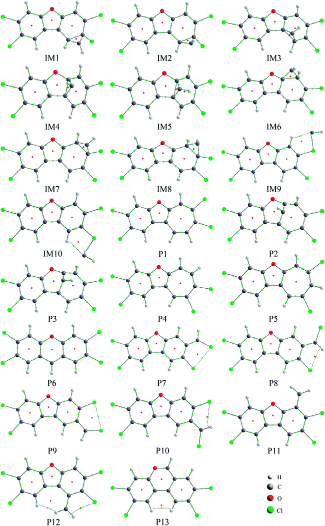 | ||
| Fig. 5 The molecular graphs for the initial intermediates and products, where the BCP and RCP are denoted as small green and red dots, respectively. | ||
| Species | BCP | ρbcp | ∇2ρbcp | Vbcp | Gbcp | Hbcp |
|---|---|---|---|---|---|---|
| a Atomic numbering refers to Fig. 2. The ρbcp, ∇2ρbcp, Vbcp, Gbcp, and Hbcp is electron density, the Laplacian of the electron density, potential energy density, kinetic energy density, and energy density at the BCP, respectively. | ||||||
| IM1 | C1 – C22 | 0.2655 | −0.5642 | −0.3437 | 0.1013 | −0.2423 |
| C2 – C22 | 0.2510 | −0.4894 | −0.3128 | 0.0952 | −0.2176 | |
| IM2 | C1 – C22 | 0.2640 | −0.5524 | −0.3400 | 0.1009 | −0.2390 |
| C2 – C22 | 0.2541 | −0.5054 | −0.3187 | 0.0962 | −0.2225 | |
| IM3 | C2 – C22 | 0.2608 | −0.5541 | −0.3296 | 0.0955 | −0.2341 |
| C3 – C22 | 0.2564 | −0.5234 | −0.3223 | 0.0957 | −0.2266 | |
| IM4 | C3 – C22 | 0.2430 | −0.4407 | −0.3003 | 0.0951 | −0.2053 |
| C4 – C22 | 0.2671 | −0.5773 | −0.3443 | 0.1000 | −0.2443 | |
| IM5 | C3 – C22 | 0.2525 | −0.4992 | −0.3166 | 0.0959 | −0.2207 |
| C4 – C22 | 0.2646 | −0.5662 | −0.3396 | 0.0990 | −0.2406 | |
| IM6 | C4 – C22 | 0.2691 | −0.5909 | −0.3462 | 0.0992 | −0.2470 |
| C5 – C22 | 0.2543 | −0.5095 | −0.3185 | 0.0955 | −0.2229 | |
| IM7 | C5 – C22 | 0.2475 | −0.4697 | −0.3072 | 0.0949 | −0.2123 |
| C6 – C22 | 0.2679 | −0.5792 | −0.3477 | 0.1014 | −0.2462 | |
| IM8 | C5 – C22 | 0.2508 | −0.4852 | −0.3130 | 0.0958 | −0.2171 |
| C6 – C22 | 0.2661 | −0.5649 | −0.3434 | 0.1011 | −0.2423 | |
| IM9 | Cl21 – C22 | 0.0904 | 0.0614 | −0.0820 | 0.0487 | −0.0333 |
| IM10 | Cl20 – C22 | 0.0904 | 0.0607 | −0.0819 | 0.0486 | −0.0334 |
| P1 | C1 – C22 | 0.2792 | −0.7172 | −0.3365 | 0.0786 | −0.2579 |
| C2 – C22 | 0.3259 | −0.9353 | −0.4733 | 0.1197 | −0.3536 | |
| P2 | C3 – C22 | 0.2697 | −0.6614 | −0.3211 | 0.0779 | −0.2432 |
| C4 – C22 | 0.2824 | −0.7287 | −0.3489 | 0.0834 | −0.2655 | |
| P3 | C3 – C22 | 0.2763 | −0.6890 | −0.3400 | 0.0839 | −0.2562 |
| C4 – C22 | 0.2862 | −0.7418 | −0.3669 | 0.0907 | −0.2762 | |
| P4 | C4 – C22 | 0.3017 | −0.8479 | −0.3969 | 0.0925 | −0.3044 |
| C5 – C22 | 0.3071 | −0.8482 | −0.4162 | 0.1021 | −0.3141 | |
| P5 | C1 – C22 | 0.2868 | −0.7536 | −0.3582 | 0.0849 | −0.2733 |
| C6 – C22 | 0.3087 | −0.8511 | −0.4263 | 0.1067 | −0.3195 | |
| P6 | C3 – C22 | 0.2953 | −0.7939 | −0.3783 | 0.0899 | −0.2884 |
| C8 – C22 | 0.2953 | −0.7938 | −0.3783 | 0.0899 | −0.2884 | |
| P7 | C6 – C22 | 0.2970 | −0.7854 | −0.3867 | 0.0952 | −0.2915 |
| Cl21 – C22 | 0.2051 | −0.3055 | −0.2234 | 0.0735 | −0.1499 | |
| P8 | C6 – C22 | 0.3022 | −0.8157 | −0.3985 | 0.0973 | −0.3012 |
| Cl21 – C22 | 0.2024 | −0.2997 | −0.2199 | 0.0725 | −0.1474 | |
| P9 | C1 – C22 | 0.2927 | −0.7643 | −0.3749 | 0.0919 | −0.2830 |
| Cl20 – C22 | 0.2043 | −0.3021 | −0.2223 | 0.0734 | −0.1489 | |
| P10 | C1 – C22 | 0.2979 | −0.7948 | −0.3869 | 0.0941 | −0.2928 |
| Cl20 – C22 | 0.2015 | −0.2962 | −0.2188 | 0.0724 | −0.1464 | |
| P11 | C5 – C22 | 0.3045 | −0.8350 | −0.4102 | 0.1007 | −0.3095 |
| P12 | C2 – C22 | 0.3078 | −0.8515 | −0.4166 | 0.1018 | −0.3147 |
| P13 | C4 – C22 | 0.3110 | −0.8653 | −0.4227 | 0.1032 | −0.3195 |
| O13 – C22 | 0.2735 | −0.0999 | −0.7395 | 0.3573 | −0.3822 | |
Subsequently, the initial intermediates IM1, IM2, and IM3 undergo the corresponding transition states TS2, TS3, and TS4 to form the product P1, i.e., IM1 → TS2 → P1, IM2 → TS3 → P1, and IM3 → TS4 → P1, where P1 is characterized by a planar seven-membered ring structure. The energy barriers of the three processes are 1.52, 2.77, and −0.25(0.28) kcal mol−1 respectively, where the value in parentheses is the result without considering the ZPVE corrections. Moreover, the above processes are spontaneous and highly exothermic reactions, where the corresponding enthalpy (Gibbs free energy) changes are −48.01(−48.18), −47.87(−48.07), and −58.10(−58.11) kcal mol−1, respectively. Therefore, P1 should be the dominant product and the pathway IM3 → TS4 → P1 is the optimal pathway to produce it.
Subsequently, the initial intermediates IM4 and IM5 can undergo the corresponding transition states TS7 and TS8 to produce the ring-expanded products P2 and P3, i.e., IM4 → TS7 → P2 and IM5 → TS8 → P3. For the two processes, the energy barriers are 1.18 and −0.14(0.14) kcal mol−1 respectively, where the value in parentheses is the result without considering ZPVE corrections. Moreover, the above processes are exothermic and spontaneous processes, where the corresponding enthalpy (Gibbs free energy) changes are −1.17(−1.14) and −3.75(−3.33) kcal mol−1, respectively. Therefore, it is easy to convert into products P2 and P3 for IM4 and IM5.
After then, the above three intermediates can undergo the corresponding transition states to produce the ring-expanded product P4, i.e., IM6 → TS11 → P4, IM7 → TS13 → P4, and IM8 → TS14 → P4, where the energy barriers are 0.03, 1.64, and 3.19 kcal mol−1, respectively. Moreover, the above processes are exothermic and spontaneous processes, where the corresponding enthalpy (Gibbs free energy) changes are −55.94(−56.08), −48.32(−48.61), and −48.29(−48.62) kcal mol−1, respectively. Therefore, similar to products P1–P3, P4 should also be the dominant product. In addition, as presented in Table 2, IM4 can also convert into P4 thermodynamically, where the corresponding enthalpy and Gibbs free energy changes are −65.22 and −65.62 kcal mol−1, respectively. However, the high energy barrier of 34.67 kcal mol−1 suggests that it is difficult to occur for this process. Therefore, the IM6 → TS11 → P4 process should be the optimal pathway to produce product P4.
Subsequently, IM9 and IM10 can undergo corresponding transition states to produce products P7–P10, i.e., IM9 → TS18 → P7, IM9 → TS19 → P8, IM10 → TS25 → P9, and IM10 → TS26 → P10, where the energy barrier of each process is 12.37, 12.51, 13.64, and 13.94 kcal mol−1, respectively. Moreover, all the above reaction processes are exothermic and spontaneous processes, where the corresponding enthalpy (Gibbs free energy) changes are −100.38(−99.10), −106.31(−104.75), −98.62(−97.48), and −104.54(−103.04) kcal mol−1, respectively. Additionally, it was also found that IM8 can be converted into P8 via TS23 with an energy barrier of 27.36 kcal mol−1, implying that it is difficult to proceed under normal conditions. Compared with the products P1–P4 mentioned above, the formation of the products P7–P10 requires higher energy barriers to overcome. Moreover, as the precursors to the products P7–P10, IM9 and IM10 are unfavorable to be formed thermodynamically relative to the other intermediates. Therefore, products P7–P10 should be the secondary products of the title reaction.
3.2 Analyses of stability and interconversion of products
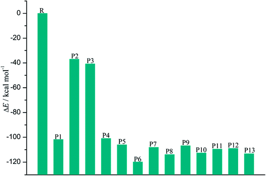
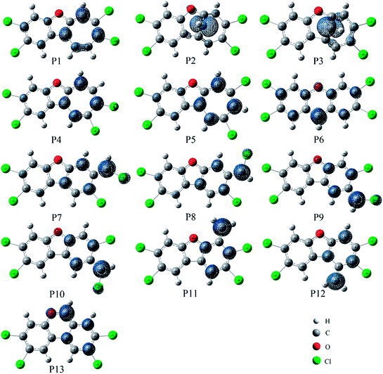
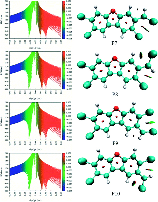
As shown in Fig. 7, the distributions of the unpaired electron in the products are different depending on the position of the inserted CH radical. According to the degree of the delocalization of the unpaired electron, the products can be divided into four groups, namely, (1) P6, (2) P7–P13, (3) P1, P4, and P5, (4) P2 and P3. In more details, for the most stable product P6, its single electron is distributed widely around the C atom of the inserted CH radical and its adjacent two rings. For the second group, the single electron is mainly distributed on the C atom of the inserted CH radical and its adjacent ring. As shown in Fig. 6, the stabilities of these products including P7–P13 are also similar to each other. Here, note that P8 is more stable than P7, which should be due to the favorable intramolecular H-bonds in P8. To further clarify this point, we have carried out the RDG analysis of P7 and P8. As displayed in Fig. 8, two intramolecular H-bonds H16⋯Cl21 and H23⋯Cl20 in P8 can be confirmed by the appearance of the corresponding spikes between H and Cl atoms. However, two repulsion interactions including the H16⋯H23 and Cl20⋯Cl21 atoms can be observed in P7. Similarly, the same phenomena can also be observed in P9 and P10. As for the third group including the products P1, P4, and P5, their single electrons are mainly distributed on the selected ring associated with the inserted CH radical. As for the forth group including the least stable products P2 and P3, the single electron is only localized on the C atom of the inserted CH radical. Obviously, the above analyses suggest that the stability of the products is mainly controlled by the distribution of the single electron overall, i.e., the wider the single electron distribution is, the more stable the product is.
As presented in Table 2, for the formation processes of the products P1–P4, the corresponding energy barriers are no more than 4 kcal mol−1, indicating that these reactions can occur easily. On the contrary, as for the products P5 and P6, they are difficult to be formed as can be seen from the high energy barriers, where the corresponding energy barriers are 50.93 and 129.47 kcal mol−1, respectively. Similarly, the same is also true for the products P11–P13. As for the products P7–P10, the corresponding energy barriers ranging from 12.37 to 13.94 kcal mol−1 are higher than those of the products P1–P4. Moreover, the initial intermediates IM9 and IM10 associated with the formation of P7–P10 are unfavorable thermodynamically. As a result, the formation of the products P7–P10 has no competitive with the P1–P4. In addition, given the fact that the product P2 is very easy to convert to P3 as mentioned above, we can say that P1, P3, and P4 should be the most favorable products of the title reaction.
3.3 Molecular dynamics analysis
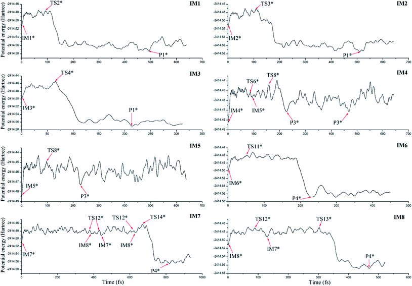
To further confirm the possibility of the formation of the dominant products and their dynamic stability, ab initio molecular dynamics has been performed on the basis of the optimized initial intermediates. Here, only the initial intermediates IM1-IM8 have been considered due to the low thermodynamic stability of the initial intermediates IM9 and IM10 as mentioned above.As shown in Fig. 9, for the initial intermediates IM1, IM2, and IM3, they have been finally converted to product P1 at different time scales, where the corresponding transition states TS2, TS3, and TS4 can be observed during the dynamic processes. Similarly, for IM4 and IM5, they have been finally converted to product P3. Here, the conversion from IM4 to IM5 via TS6 has also been observed. As for IM6, IM7, and IM8, the product P4 has been obtained after the corresponding conversion. Therefore, the formed initial intermediates can be easily converted to the products P1, P3, and P4, which is also consistent with the above analyses.
3.4 IR spectra and hyperfine coupling constants of the dominant products
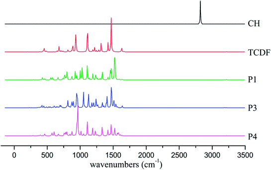
To provide useful information for the detection and identification of the products using IR and electron spin resonance (ESR) techniques, the IR spectra and the hyperfine coupling constants (hfcc's) of the dominant products including P1, P3, and P4 have been analyzed.As shown in Fig. 10, the characteristic absorption peaks of the CH radical and TCDF appear at about 2821 and 1469 cm−1, corresponding to the stretching vibration of the C–H bond and the rocking vibration of the C–H bond in the ring, respectively. However, the former C–H vibration disappears in the products. As for the latter, they can still be observed at about 1522 cm−1 (P1), 1472 cm−1 (P3), and 1470 cm−1 (P4), respectively. Moreover, the IR absorption peaks of each product have their own characteristics. For example, for the product P1, a strong absorption peak could be observed at about 1107 cm−1, corresponding to the rocking vibration of the C–H bond in the non-reactive ring. For the product P3, a strong absorption peak occurs at about 947 cm−1, which mainly corresponds to the distortion vibration of the two rings. As for the product P4, its characteristic absorption peak appears at about 962 cm−1, which mainly corresponds to the stretching vibration of the C–C bond in the reactive ring. Obviously, these different features of the IR spectra of the products can provide some help in the identification of them using the gas-phase vibrational spectrum experimentally.
In view of the fact that the products have short lifespan and high reactivity due to the existence of the single unpaired electron, so it is difficult to detect and characterize them experimentally. At present, the electron spin resonance (ESR) technique is one of the effective spectroscopic methods to detect free radicals via providing the hfcc's. In the case of lacking relevant experimental information, theoretical predictions are highly desirable. As shown in Table 4, depending on the specific products, all the results of the hfcc's are different in signs and values except for four chlorine atoms. For example, the hfcc's of 13C1 are 9.9 (P1), 1.2 (P3), and −8.1 G (P4), respectively. Especially, as for the C22 atom of the introduced CH radical, the hfcc is −3.0, 73.5, and 9.4 G in P1, P3, and P4, respectively. Obviously, the different hfcc results can be used to identify the different products experimentally.
| Atom numberings | Atom | P1 | P3 | P4 |
|---|---|---|---|---|
| a All the units are in Gauss. | ||||
| 1 | 13C | 9.9 | 1.2 | −8.1 |
| 2 | 13C | −1.0 | 8.8 | 2.9 |
| 3 | 13C | 5.7 | −1.1 | 2.6 |
| 4 | 13C | −9.4 | −9.7 | −7.3 |
| 5 | 13C | 10.6 | 7.7 | −10.7 |
| 6 | 13C | −11.5 | 0.1 | 13.8 |
| 7 | 13C | 2.2 | −0.4 | 1.8 |
| 8 | 13C | −5.5 | 6.8 | −4.3 |
| 9 | 13C | −2.6 | 0.5 | −2.2 |
| 10 | 13C | 2.8 | 0.6 | 2.2 |
| 11 | 13C | 3.8 | −0.2 | 3.2 |
| 12 | 13C | −3.5 | 1.0 | −2.9 |
| 13 | 17O | 0.1 | −0.5 | 0.1 |
| 14 | 1H | −2.4 | 0.2 | −2.0 |
| 15 | 1H | −2.7 | −0.4 | −5.3 |
| 16 | 1H | −9.9 | 0.3 | 3.1 |
| 17 | 1H | 0.8 | −0.1 | 0.7 |
| 18 | 35Cl | 0.0 | 0.0 | 0.0 |
| 19 | 35Cl | 0.1 | 0.0 | 0.1 |
| 20 | 35Cl | 0.2 | 0.2 | −0.1 |
| 21 | 35Cl | −0.1 | 0.1 | 0.3 |
| 22 | 13C | −3.0 | 73.5 | 9.4 |
| 23 | 1H | −1.6 | −8.8 | −8.9 |
3.5 Substitution effects
To further validate the feasibility of the reactions between CH radical and other TCDF derivatives, the reactions of F- and Br-substituted TCDFs with CH radical have been investigated on the basis of the above reactions, where only the selected pathways associated with the dominant products P1, P3, and P4 have been considered. As displayed in Fig. 11, similar to the above reactions without substitution, the initial intermediates, transition states, and products involved in the reactions have also been located, where the relevant geometries before and after substitution were similar to each other. Moreover, as shown in Tables 1 and 2, the calculated thermodynamic and kinetic data, such as enthalpy changes, Gibbs free energy changes, and energy barriers are also similar to those before substitution. For example, the whole reaction processes are exothermic and spontaneous thermodynamically as can be seen from the negative enthalpy and Gibbs free energy changes. Meanwhile, each pathway has low energy barrier, which is no more than 5 kcal mol−1. Therefore, similar to TCDF, its derivatives can also react with CH radical in the gas phase, resulting in the transformation of them in geometry and property. Certainly, relevant experiments are required to further confirm this point in the future.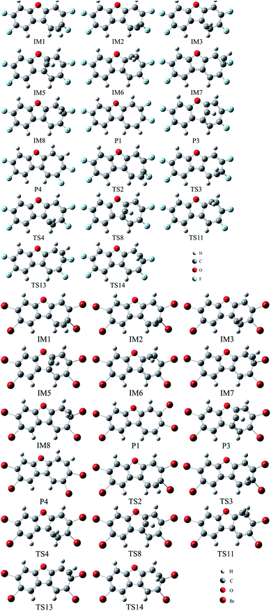 | ||
| Fig. 11 The optimized initial intermediates (IM), transition states (TS), and the products in the reactions of F- and Br-substituted TCDFs with CH radical. | ||
4. Conclusions
In this study, all of the possible reaction modes for the insertion of the CH radical into the C–X(X = C, Cl, H, O) bonds of TCDF have been systematically investigated employing B3LYP method in combination with the ab initio molecular dynamics. As a result, it was found that CH radical can react with TCDF via the insertion modes, i.e., an initial intermediate is formed firstly followed by the formation of a more stable product characterized by an expanded six- or seven-membered ring structure. Thermodynamically, the whole reaction processes are spontaneous and exothermic reactions and the thermodynamic stability of the products is controlled by the distribution of the single unpaired electron. Kinetically, the most favorable reaction channel is the insertion of the CH radical into the C–C bond except for the C atoms attached to the chlorine atom, producing the seven-membered ring compound. The dominant products have been further confirmed by the molecular dynamics. Moreover, the different distinct characteristics of IR and hyperfine coupling constants can provide some help in the detection and identification of the dominant products experimentally. In addition, similar to TCDF, the F- and Br-substituted TCDFs can also react with CH radical thermodynamically and kinetically. Expectedly, the present results can provide new insights into the transformation of TCDF and the potential role of CH radical in the atmosphere. Certainly, more extensive experiments are highly required to further confirm these computational results in the future.Conflicts of interest
There are no conflicts to declare.Acknowledgements
This work is supported by National Natural Science Foundation of China (21577076, 21303093), Natural Science Foundation of Shandong Province (ZR2018MB020), and the Doctoral Foundation of Shandong Province (ZR2016BB20, ZR2017BB055).References
- L. L. Zou, Y. W. Ni, Y. Gao, F. M. Tang, J. Jin and J. P. Chen, Chemosphere, 2018, 195, 491–497 CrossRef PubMed.
- E. N. Sappington, A. Balasubramani and H. S. Rifai, Chemosphere, 2015, 133, 82–89 CrossRef PubMed.
- X. L. Wang, Y. W. Ni, H. J. Zhang, X. P. Zhang and J. P. Chen, Environ. Sci. Technol., 2012, 46, 12234–12240 CrossRef PubMed.
- X. Wang, H. Zhang, Y. Ni, Q. Du, X. Zhang and J. Chen, Environ. Sci. Technol., 2014, 48, 4361–4367 CrossRef PubMed.
- M. Salamanca, C. Chandia and A. Hernandez, Sci. Total Environ., 2016, 573, 1397–1405 CrossRef PubMed.
- H. Dwyer and N. J. Themelis, Waste Manag., 2015, 46, 242–246 CrossRef PubMed.
- N. V. Heeb, M. D. Rey, M. Zennegg, R. Haag, A. Wichser, P. Schmid, C. Seiler, P. Honegger, K. Zeyer, J. Mohn, S. Burki, Y. Zimmerli, J. Czerwinski and A. Mayer, Environ. Sci. Technol., 2015, 49, 9273–9279 CrossRef PubMed.
- N. V. Heeb, M. Zennegg, R. Haag, A. Wichser, P. Schmid, C. Seiler, A. Ulrich, P. Honegger, K. Zeyer, L. Emmenegger, P. Bonsack, Y. Zimmerli, J. Czerwinski, M. Kasper and A. Mayer, Environ. Sci. Technol., 2013, 47, 6510–6517 CrossRef PubMed.
- A. C. Hieke, R. Brinkmeyer, K. M. Yeager, K. Schindler, S. Zhang, C. Xu, P. Louchouarn and P. H. Santschi, Mar. Biotechnol., 2016, 18, 630–644 CrossRef PubMed.
- A. Hidayat and S. Tachibana, Int. Biodeterior. Biodegrad., 2013, 77, 51–55 CrossRef.
- M. Govindan and I. S. Moon, Chem. Eng. J., 2015, 272, 145–150 CrossRef.
- N. Palanisami, S. J. Chung and I. S. Moon, J. Ind. Eng. Chem., 2015, 28, 28–31 CrossRef.
- P. Liljelind, J. Unsworth, O. Maaskant and S. Marklund, Chemosphere, 2001, 42, 615–623 CrossRef PubMed.
- E. Finocchio, G. Busca and M. Notaro, Appl. Catal., B, 2006, 62, 12–20 CrossRef.
- T. Daikoku, M. Takemoto, Y. Yoshida, T. Okuda, Y. Takahashi, K. Ota, F. Tokuoka, A. T. Kawaguchi and K. Shiraki, Aerosol Air Qual. Res., 2015, 15, 1469–1484 Search PubMed.
- L. Y. Huang, G. J. Su, Y. X. Liu, L. W. Li, S. Liu, H. J. Lu and M. H. Zheng, RSC Adv., 2014, 4, 25453–25460 RSC.
- M. F. Yu, X. Q. Lin, X. D. Li, T. Chen and J. H. Yan, Aerosol Air Qual. Res., 2016, 16, 2011–2022 CrossRef.
- P. C. Hung, S. H. Chang, C. C. Ou-Yang and M. B. Chang, Chemosphere, 2016, 144, 50–58 CrossRef PubMed.
- Y. Hajizadeh, J. A. Onwudili and P. T. Williams, Waste Manag., 2011, 31, 1194–1201 CrossRef PubMed.
- A. Kawashima, M. Katayama, N. Matsumoto and K. Honda, Chemosphere, 2011, 83, 823–830 CrossRef PubMed.
- K. Zhang, S. M. Sun and H. Zhang, RSC Adv., 2015, 5, 81153–81161 RSC.
- X. M. Sun, C. X. Zhang, Y. Y. Zhao, J. Bai, Q. Z. Zhang and W. X. Wang, Environ. Sci. Technol., 2012, 46, 8148–8155 CrossRef PubMed.
- C. X. Zhang, X. M. Sun, Y. S. Xu, C. S. Qi and J. H. Zhang, J. Environ. Chem. Eng., 2014, 2, 1098–1103 CrossRef.
- W. X. Pan, Y. Y. Qi, R. X. Wang, Z. Han, D. J. Zhang and J. H. Zhan, Chemosphere, 2013, 91, 157–164 CrossRef PubMed.
- Q. X. Zhou, Y. L. Yong, W. W. Ju, X. Y. Su, X. H. Li, C. Y. Wang and Z. B. Fu, Curr. Appl. Phys., 2018, 18, 61–67 CrossRef.
- N. Love, R. N. Parthasarathy and S. R. Gollahalli, Int. J. Green Energy, 2011, 8, 113–120 CrossRef.
- F. V. Tinaut, M. Reyes, B. Gimenez and J. V. Pastor, Energy Fuels, 2011, 25, 119–129 CrossRef.
- K. McKee, M. A. Blitz, K. J. Hughes, M. J. Pilling, H. B. Qian, A. Taylor and P. W. Seakins, J. Phys. Chem. A, 2003, 107, 5710–5716 CrossRef.
- P. Fleurat-Lessard, J. C. Rayez, A. Bergeat and J. C. Loison, Chem. Phys., 2002, 279, 87–99 CrossRef.
- J. M. Ribeiro and A. M. Mebel, J. Phys. Chem. A, 2014, 118, 9080–9086 CrossRef PubMed.
- J. M. Ribeiro and A. M. Mebel, Mol. Phys., 2015, 113, 1865–1872 CrossRef.
- J. M. Ribeiro and A. M. Mebel, J. Phys. Chem. A, 2016, 120, 1800–1812 CrossRef PubMed.
- J. M. Ribeiro and A. M. Mebel, Phys. Chem. Chem. Phys., 2017, 19, 14543–14554 RSC.
- Y. Li, H. L. Liu, Z. J. Zhou, X. R. Huang and C. C. Sun, J. Phys. Chem. A, 2010, 114, 9496–9506 CrossRef PubMed.
- A. J. Trevitt, M. B. Prendergast, F. Goulay, J. D. Savee, D. L Osborn, C. A. Taatjes and S. R. Leone, J. Phys. Chem. A, 2013, 117, 6450–6457 CrossRef PubMed.
- F. Zhang, P. Maksyutenko and R. I. Kaiser, Phys. Chem. Chem. Phys., 2012, 14, 529–537 RSC.
- F. Goulay, A. J. Trevitt, G. Meloni, T. M. Selby, D. L. Osborn, C. A. Taatjes, L. Vereecken and S. R. Leone, J. Am. Chem. Soc., 2009, 131, 993–1005 CrossRef PubMed.
- J. C. Loison and A. Bergeat, Phys. Chem. Chem. Phys., 2009, 11, 655–664 RSC.
- L. R. McCunn, B. L. FitzPatrick, M. J. Krisch, L. J. Butler, C. W. Liang and J. J. Lin, J. Chem. Phys., 2006, 125, 133306 CrossRef PubMed.
- H. Thiesemann, J. MacNamara and C. A. Taatjes, J. Phys. Chem. A, 1997, 101, 1881–1886 CrossRef.
- S. Soorkia, C. A. Taatjes, D. L. Osborn, T. M. Selby, A. J. Trevitt, K. R. Wilson and S. R. Leone, Phys. Chem. Chem. Phys., 2010, 12, 8750–8758 RSC.
- J. F. Lockyear, O. Welz, J. D. Savee, F. Goulay, A. J. Trevitt, C. A. Taatjes, D. L. Osborn and S. R. Leone, J. Phys. Chem. A, 2013, 117, 11013–11026 CrossRef PubMed.
- F. Goulay, C. Rebrion-Rowe, L. Biennier, S. D. Le Picard, A. Canosa and B. R. Rowe, J. Phys. Chem. A, 2006, 110, 3132–3137 CrossRef PubMed.
- D. G. Johnson, M. A. Blitz and P. W. Seakins, Phys. Chem. Chem. Phys., 2000, 2, 2549–2553 RSC.
- A. J. Trevitt and F. Goulay, Phys. Chem. Chem. Phys., 2016, 18, 5867–5882 RSC.
- E. Mazarei and S. H. Mousavipour, J. Phys. Chem. A, 2017, 121, 8033–8047 CrossRef PubMed.
- F. Goulay, A. J. Trevitt, J. D. Savee, J. Bouwman, D. L. Osborn, C. A. Taatjes, K. R. Wilson and S. R. Leone, J. Phys. Chem. A, 2012, 116, 6091–6106 CrossRef PubMed.
- K. Xu, W. Wang, W. Wei, W. Feng, Q. Sun and P. Li, J. Phys. Chem. A, 2017, 121, 7236–7245 CrossRef PubMed.
- C. Guo, W. Wang, W. Feng and P. Li, RSC Adv., 2017, 7, 12775–12782 RSC.
- W. Wang, C. Guo, W. Feng, Q. Sun and P. Li, RSC Adv., 2017, 7, 32419–32426 RSC.
- P. Li, W. Wang, Q. Sun, Z. Li, A. Du, S. Bi and Y. Zhao, ChemPhysChem, 2013, 14, 2737–2743 CrossRef PubMed.
- P. Li, Z. Shen, W. Wang, Z. Ma, S. Bi, H. Sun and Y. Bu, Phys. Chem. Chem. Phys., 2010, 12, 5256–5267 RSC.
- W. Feng, C. Ren, W. Wang, C. Guo, Q. Sun and P. Li, Theor. Chem. Acc., 2016, 135, 190 CrossRef.
- W. Feng, C. Ren, W. Wang, C. Guo, Q. Sun and P. Li, RSC Adv., 2016, 6, 48099–48108 RSC.
- W. Wang, X. Zhang, P. Li, Q. Sun, Z. Li, C. Ren and C. Guo, J. Phys. Chem. A, 2015, 119, 796–805 CrossRef PubMed.
- P. Li, Z. Ma, W. Wang, Y. Zhai, H. Sun, S. Bi and Y. Bu, Phys. Chem. Chem. Phys., 2011, 13, 941–953 RSC.
- P. Li, Z. Ma, W. Wang, R. Song, Y. Zhai, S. Bi, H. Sun and Y. Bu, Phys. Chem. Chem. Phys., 2011, 13, 5931–5939 RSC.
- C. Gonzalez and H. B. Schlegel, J. Chem. Phys., 1989, 90, 2154–2161 CrossRef.
- C. Gonzalez and H. B. Schlegel, J. Phys. Chem., 1990, 94, 5523–5527 CrossRef.
- L. F. Pacios, J. Phys. Chem. A, 2004, 108, 1177–1188 CrossRef.
- W. D. Arnold and E. Oldfield, J. Am. Chem. Soc., 2000, 122, 12835–12841 CrossRef.
- T. Lu and F. Chen, J. Comput. Chem., 2012, 33, 580–592 CrossRef PubMed.
- H. B. Schlegel, J. M. Millam, S. S. Iyengar, G. A. Voth, A. D. Daniels, G. E. Scuseria and M. J. Frisch, J. Chem. Phys., 2001, 114, 9758–9763 CrossRef.
- S. S. Iyengar, H. B. Schlegel, J. M. Millam, G. A. Voth, G. E. Scuseria and M. J. Frisch, J. Chem. Phys., 2001, 115, 10291–10302 CrossRef.
- H. B. Schlegel, S. S. Iyengar, X. Li, J. M. Millam, G. A. Voth, G. E. Scuseria and M. J. Frisch, J. Chem. Phys., 2002, 117, 8694–8704 CrossRef.
- M. J. Frisch, G. W. Trucks, H. B. Schlegel, G. E. Scuseria, M. A. Robb, J. R. Cheeseman, G. Scalmani, V. Barone, B. Mennucci, G. A. Petersson, H. Nakatsuji, M. Caricato, X. Li, H. P. Hratchian, A. F. Izmaylov, J. Bloino, G. Zheng, J. L. Sonnenberg, M. Hada, M. Ehara, K. Toyota, R. Fukuda, J. Hasegawa, M. Ishida, T. Nakajima, Y. Honda, O. Kitao, H. Nakai, T. Vreven, J. A. Montgomery Jr., J. E. Peralta, F. Ogliaro, M. Bearpark, J. J. Heyd, E. Brothers, K. N. Kudin, V. N. Staroverov, T. Keith, R. Kobayashi, J. Normand, K. Raghavachari, A. Rendell, J. C. Burant, S. S. Iyengar, J. Tomasi, M. Cossi, N. Rega, J. M. Millam, M. Klene, J. E. Knox, J. B. Cross, V. Bakken, C. Adamo, J. Jaramillo, R. Gomperts, R. E. Stratmann, O. Yazyev, A. J. Austin, R. Cammi, C. Pomelli, J. W. Ochterski, R. L. Martin, K. Morokuma, V. G. Zakrzewski, G. A. Voth, P. Salvador, J. J. Dannenberg, S. Dapprich, A. D. Daniels, O. Farkas, J. B. Foresman, J. V. Ortiz, J. Cioslowski, D. J. Fox, Gaussian, Inc., Wallingford CT, 2013.
Footnote |
| † Electronic supplementary information (ESI) available. See DOI: 10.1039/c8ra03046d |
| This journal is © The Royal Society of Chemistry 2018 |


