DOI:
10.1039/C8RA03039A
(Paper)
RSC Adv., 2018,
8, 19776-19785
Nickel-foam-supported β-Ni(OH)2 as a green anodic catalyst for energy efficient electrooxidative degradation of azo-dye wastewater†
Received
9th April 2018
, Accepted 11th May 2018
First published on 30th May 2018
Abstract
Electrochemical oxidative degradation (EOD) is a particularly promising technique for removing organic pollutants from wastewater. However, due to the high overpotential of EOD in conventional anode materials, the energy cost of EOD is usually very high, which greatly promotes the search for highly active, stable, and energy-efficient anodic catalysts. Herein, we demonstrated that nickel-foam-supported (NF-supported) β-Ni(OH)2 (NF/β-Ni(OH)2) prepared via a facile hydrothermal method could be used as an energy efficient anode for EOD. The as-prepared 3D porous NF/β-Ni(OH)2 exhibited high activity toward the electrochemical oxidation of methyl orange (MO) in the low potential region (<1.07 V vs. SCE). This property differs greatly from those of the conventional anode materials that require a high positive potential to keep them active for EOD, making NF/β-Ni(OH)2 an energy-efficient and active anode material for EOD. With an oxidation current density of 0.25 mA cm−2, the decolorization of MO was completed within 30 min, and the COD removal after 3h of reaction was 63.0%. The normalized energy consumption for the 3 h degradation of MO was 22.2 kW h (kg COD)−1, which is only a fraction of (or even one tenth of) the values reported in the literature. Moreover, NF/β-Ni(OH)2 had a good stability and recyclability for EOD. No activity decay was observed during 10 h of EOD and the COD removal remained almost unchanged after four consecutive reaction cycles. We demonstrated experimentally that the NF/β-Ni(OH)2 anode could generate large amounts of hydroxyl radicals and that the oxidation of MO by hydroxyl radicals was the main mechanism during EOD. We believe that this work opens a new avenue for developing highly active and energy-efficient anode materials that can work in the low potential region for EOD.
1. Introduction
There has been increasing public concern regarding environmental contamination problems arising from rapidly developing industries in the past few decades.1 The textile and printing industry is regarded as one of the most polluting sectors due to its massive discharge of dye wastewater, which is usually highly coloured, toxic, and hard to degrade. Among these dyes, azo dyes account for over 70% of commercial dyestuff,2 thereby making them the most important and widely used synthetic dyes in the printing and dyeing industry. Azo dyes contain at least one azo group (–N![[double bond, length as m-dash]](https://www.rsc.org/images/entities/char_e001.gif) N–) that is bonded to aromatic moieties containing functional groups such as –OH and–SO3H.3 A variety of physical, chemical, and biological methods4–6 have been developed to treat dye wastewater but most of them have been proven to be ineffective for the removal of dye compounds. In recent years, advanced oxidation processes (AOPs) have been proposed as efficient and emerging alternatives for the treatment of wastewater containing toxic or refractory organic pollutants.7 AOPs include many oxidation techniques such as Fenton oxidation,8 ozonation,9 photocatalytic oxidation,10 wet air oxidation,11 electrochemical oxidation12 and the combination of two oxidation processes.3,7,13,14
N–) that is bonded to aromatic moieties containing functional groups such as –OH and–SO3H.3 A variety of physical, chemical, and biological methods4–6 have been developed to treat dye wastewater but most of them have been proven to be ineffective for the removal of dye compounds. In recent years, advanced oxidation processes (AOPs) have been proposed as efficient and emerging alternatives for the treatment of wastewater containing toxic or refractory organic pollutants.7 AOPs include many oxidation techniques such as Fenton oxidation,8 ozonation,9 photocatalytic oxidation,10 wet air oxidation,11 electrochemical oxidation12 and the combination of two oxidation processes.3,7,13,14
Among these AOPs, electrochemical oxidation degradation (EOD) has attracted ever increasing interest due to its advantages, such as its high efficiency, ease of manipulation and lower generation of by-products during the removal of organic pollutants.15 However, in a typical EOD process, high potentials are required to maintain the high activity of the anode materials toward the oxidation of organic pollutants. Under highly positive potentials, other competing electrochemical oxidation processes such as the oxygen evolution reaction (OER) are also promoted,16 resulting in an unnecessary loss of energy. In order to suppress the oxidation of water at high potential, great efforts have been made to develop anode materials that have a high overpotential for the OER. For example, SnO2- and PbO2-based materials have been widely adopted as anodes for the EOD of organic pollutants because both SnO2 and PbO2 exhibit a very high overpotential for water oxidation.17–20 However, SnO2- and PbO2-based anode materials are not environmentally sustainable due to the following facts: SnO2 anodes are often doped with highly toxic Sb to increase their conductivity and improve their activity for EOD21, and PbO2 anodes may result in the leaching of highly toxic lead ions into solution under anodic oxidation conditions.19,22 Boron-doped diamond (BDD), as another anode material with a high OER overpotential, has received great attention due to its green chemical composition and good activity for EOD.15,23 However, the preparation of BDD film is economically unfavorable,22 and the obtained film usually cracks and detaches from the conducting substrate after long-term EOD, making it unfeasible for large-scale and long-term utilization in practice.7,15 Moreover, an intrinsic drawback of anode materials with a high OER overpotential is that they are active only at high potentials, which inevitably leads to a high energy cost. Therefore, it is highly desirable to develop new anode materials with high catalytic activity, good stability and a low energy cost during EOD. Therefore, we aim to develop a new type of anode that can stably work at a low potential to achieve a high EOD efficiency with a low energy consumption.
Compared to other transition metals, nickel has a higher natural abundance and a lower toxicity, which makes it economically feasible for practical applications in industry.24 As a typical VIIIB group transition metal, nickel has several valence electrons, which make it an element with variable valence in compounds. Although nickel can exist in the +2, +3 and +4 oxidation states, Ni(II) is the stable valence state of nickel compounds in air and water under most conditions. The high valence states of nickel (e.g. Ni(III) and Ni(IV)) have strong oxidizing properties, and as a result, Ni(III) and Ni(IV) have shown promise as intermediates in a number of nickel-based catalysts for many oxidation reactions,25–27 especially the oxidation of organic compounds such as 4-chlorophenol,28,29 urea30 and alcohols.31,32 Accordingly, it is a good strategy to prepare a highly active nickel-based anode for EOD by growing a condensed film of an Ni(II) compound on a high-specific-area conducting support. During the EOD, the Ni(II) compound film will be activated via electrochemical oxidization to the high valence states of Ni(III) and Ni(IV), which are highly active for generating hydroxyl radicals33 or for directly oxidizing organic pollutants29, and will then be reduced back to Ni(II). Ni foam is an excellent support due to its 3D porous network, which provides not only a good conducting substrate but also a large specific area, both of which favour a high efficiency for EOD.34 Among nickel(II) compounds, Ni(OH)2 has been demonstrated to be active for the photodegradation of azo dyes.35,36 More importantly, Ni(OH)2 exhibits good activity and reversibility during electrochemical oxidation into high valence state Ni compounds such as NiOOH.24 This property suggests that Ni(OH)2 can act as an electrocatalyst for the EOD of organic pollutants.
The purpose of this paper is to develop a nickel-based catalyst to achieve the EOD of azo dyes with low energy consumption. We report the preparation of a nickel-foam-supported β-Ni(OH)2 (NF/β-Ni(OH)2) anode, which exhibited high catalytic activity toward the EOD of methyl orange (MO) at potentials lower than the water oxidation potential. We demonstrated that the NF/β-Ni(OH)2) anode not only was highly energy-efficient during the galvanostatic degradation of MO but also had an excellent stability and a good recyclability during EOD. We provide solid experimental evidence that a large amount of hydroxyl radicals were electrochemically generated by the NF/β-Ni(OH)2) anode during EOD, and that the oxidation of MO by hydroxyl radicals was the main mechanism in the degradation of MO. We believe that this work opens a new door to designing anode materials that are highly active toward the anodic degradation of organic pollutants with very low energy consumption.
2. Experimental section
2.1 Materials and chemicals
Ni foams (NFs, 99.99% purity, 1.7 mm thickness, 110 pores per inch (ppi) pore size) were purchased from Lizhiyuan Materials Co., Ltd. Methyl orange (MO) and terephthalic acid were purchased from Sinopharm Chemical Reagent Co., Ltd. and Shanghai Macklin Biochemical Co., Ltd., respectively. Sodium sulfate (Na2SO4, A.R.), sodium carbonate (Na2CO3, A.R.), sodium hydroxide (NaOH, A.R.), hydrogen peroxide (H2O2, 30%), ethanol (C2H5OH, A.R.) and acetone (C3H6O, A.R.) were purchased from Beijing Chemical Reagents Company. All other chemicals were of analytical grade and used without further purification. All aqueous solutions were prepared with ultrapure water (18 MΩ cm).
2.2 Hydrothermal synthesis of β-Ni(OH)2 on the surface of nickel foam
The nickel-foam-supported β-Ni(OH)2 (NF/β-Ni(OH)2) was prepared via an optimized facile one-step hydrothermal method. In detail, NF (4.0 × 9.0 cm2) was first rolled into a cylinder and then ultrasonicated successively in acetone, ethanol and deionized water each for 10 min. After being dried in air at 60 °C for 4 hours, the NF was introduced into a 50 mL Teflon-lined stainless-steel autoclave that was filled with 35 mL H2O2 aqueous solution (30 wt% concentration). The autoclave was then sealed and maintained at 180 °C for 1 hour in order to grow β-Ni(OH)2 on the surface of the NF. The obtained NF/β-Ni(OH)2 was rinsed with copious deionized water and then dried in air at 60 °C for 4 hours.
2.3 Electrochemical measurements and electrooxidative degradation
Linear sweep voltammetry and electrochemical oxidation of MO were performed on a CHI660C workstation (CH Instrument Co.) in a three-electrode cell at room temperature. The cylindrical NF/β-Ni(OH)2 electrode was employed as the working electrode. A Pt mesh and a saturated calomel electrode (SCE) were used as the counter and reference electrodes, respectively. For each degradation experiment, 50 mL MO solution of 0.2 mmol L−1 was employed as the wastewater sample, with 0.05 mol L−1 Na2SO4 (pH 7) as the supporting electrolyte. The electrochemical oxidation degradation (EOD) was conducted under galvanostatic conditions at different current densities from 0.05 to 0.50 mA m−2. All the potentials were reported with respect to the SCE, and the corresponding potentials with respect to a reversible hydrogen electrode (RHE) were also given according to the following formula:37| | |
E (V vs. RHE) = E (V vs. SCE) + 0.244 + 0.0591pH
| (1) |
2.4 Characterization and analysis method
The morphologies of the NF and NF/β-Ni(OH)2 were characterized using a field emission scanning electron microscope (FESEM) (Hitachi S-4800) operating at an accelerating voltage of 10 kV. The crystal structures of all the samples were characterized using X-ray diffraction (XRD), which was performed on an X-ray powder diffractometer (Rigaku, rint2000 advance) with Cu Kα radiation.
Samples of the MO solution were collected at certain time intervals during EOD to monitor the degradation process. In detail, the decolorization rate of the MO solution was characterized using UV-vis absorption spectroscopy (UV2600 spectrophotometer, Tianmei Co., China). The chemical oxygen demand (COD) of the sample solution was measured using the dichromate standard method.6 The total organic carbon (TOC) measurements were carried out on a TOC analyzer (TOC-VCPN, Shimadzu, Japan).
The decolorization efficiency (or percentage of color removal) was determined using the following expression:38
| |
 | (2) |
where ABS
0 and ABS
t are the average absorbance at the maximum visible wavelength (
λmax) of the wastewater before and after EOD, respectively.
The current efficiency can then be determined from ΔCOD (g dm−3) using the equation:7
| |
 | (3) |
where
F is the Faraday constant (96
![[thin space (1/6-em)]](https://www.rsc.org/images/entities/char_2009.gif)
487 C mol
−1),
Vs is the solution volume (dm
3),
I is the applied current (A), 8 is the oxygen equivalent mass (g eq
−1) and
t is the electrolysis time (s).
Energy consumption was estimated according to the following equation:39
| |
 | (4) |
where
Ecell is the average potential difference of the cell (V),
t is the EOD time (h) and
Vs is the solution volume (L). As is well known, energy consumption is proportional to the amount of organic pollutant in solution. Therefore, to make comparison easier between different EOD methods, it is necessary to normalize the energy consumption. The normalized energy consumption (NEC) can be expressed as follows when COD removal (ΔCOD) is known:
3| |
 | (5) |
The mechanism of the EOD by the NF/β-Ni(OH)2 electrode was analyzed using a fluorescence spectrophotometer (Hitachi, Japan) using terephthalic acid as the hydroxyl radical scavenger. In detail, terephthalic acid was dissolved in 0.002 mol L−1 NaOH solution to give a final concentration of 5 × 10⁻⁴ mol L−1. Then Na2SO4 was dissolved in the resulting solution with a concentration of 0.05 mol L−1 and the pH of the solution was adjusted to 7. The NF/β-Ni(OH)2 electrode was employed as the working electrode and the galvanostatic oxidation was carried out at 0.25 mA cm−2 in 0.05 mol L−1 Na2SO4 (pH 7) solution containing 5 × 10⁻⁴ M terephthalic acid. During the experiment, the solution sample was taken out every 5 min to measure the fluorescence emission spectrum (excitation at 315 nm).
3. Results and discussion
3.1 Microstructure and crystal structure of NF/β-Ni(OH)2
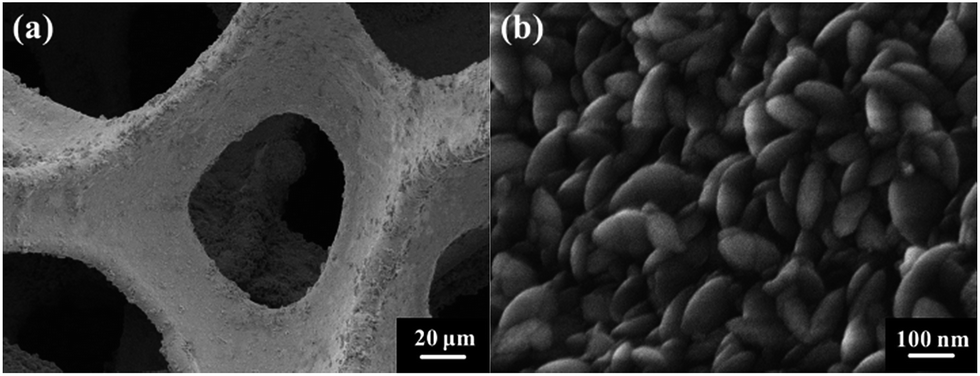
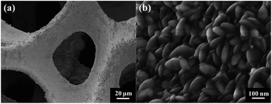
Fig. 1 shows the typical SEM images of the pristine NF and the as-prepared NF/β-Ni(OH)2. The pristine NF had a 3D porous network structure with a pore size ranging from 60 to 300 μm (Fig. 1a and S1 in the ESI†). The high magnification SEM image (Fig. 1b) reveals that the surface of the NF was quite smooth. After the hydrothermal reaction in H2O2 solution, the surface of the NF was coated with a relatively rough film, which was composed of densely stacked spindle-like β-Ni(OH)2 nanorods, as shown in Fig. 1c and d. Statistical analysis of the SEM images reveals that the spindle-like nanorods had an average length of 280 ± 30 nm and a width of 160 ± 30 nm (see Fig. S2 in the ESI†). These spindle-like β-Ni(OH)2 nanorods formed a compact film that had such a strong adhesion to the NF that it was even difficult to scratch them off the surface of the NF.
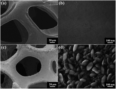 |
| | Fig. 1 Typical SEM images of the nickel foam (a) and (b), and NF/β-Ni(OH)2 (c) and (d). | |
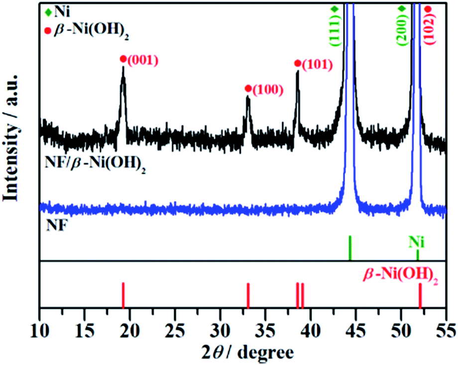
The crystal structure of the NF/β-Ni(OH)2 electrode was characterized using X-ray diffraction (XRD) and the corresponding XRD pattern is shown in Fig. 2. Along with the strong peaks representing the Ni foam substrate (JCPDS card no. 04-0850), the new diffraction peaks located at 19.3°, 33.1° and 38.5° are indexed to the hexagonal phase of β-Ni(OH)2 (JCPDS card no. 14-0117), indicating that the spindle-like nanorods observed in Fig. 1d are β-Ni(OH)2 particles. Moreover, no peaks of α-Ni(OH)2 can be identified in the XRD pattern, suggesting that pure β-Ni(OH)2 film was generated on the surface of the NF during the hydrothermal synthesis in H2O2 solution. This result is in good agreement with results reported previously.40
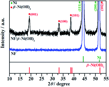 |
| | Fig. 2 XRD patterns of the nickel foam (NF) and NF/β-Ni(OH)2. | |
SEM and XRD results confirm the successful growth of β-Ni(OH)2 on the surface of the NF. In fact, the 3D porous NF played three key roles in the preparation of NF/β-Ni(OH)2 to be used as an anode material for EOD. (1) It acted as a Ni source for the in situ hydrothermal growth of β-Ni(OH)2 on its surface, and the in situ growth of β-Ni(OH)2 on the surface of the NF ensured a strong adhesion and a good electrical contact between the NF and β-Ni(OH)2. (2) It provided a large-surface-area framework for β-Ni(OH)2 to grow on, resulting in the formation of a 3D porous NF/β-Ni(OH)2 anode that had a large electrode/solution interface for the EOD of organic pollutants. (3) It provided an electrically well-connected network system, guaranteeing that all the β-Ni(OH)2 grown on the NF surface was electrochemically active for EOD.
3.2 Electrochemical oxidative degradation of methyl orange
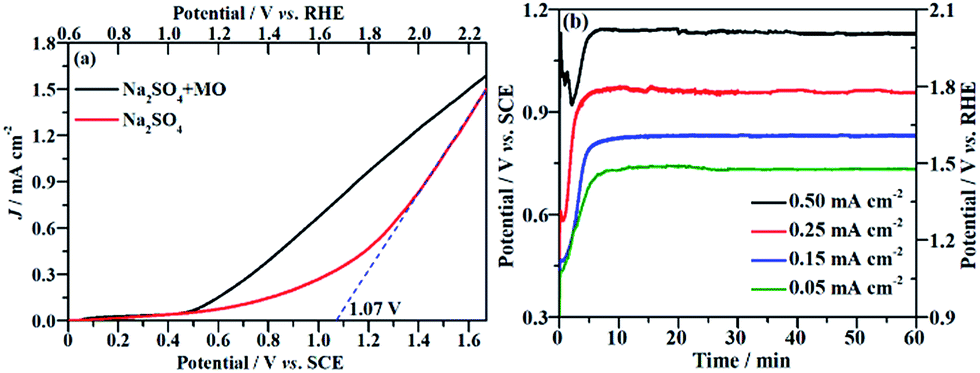
The current density (J) at the applied potential is a key parameter for the electrooxidative removal of organic pollutants because it reflects the catalytic activity of the electrode. Accordingly, linear sweep voltammetric (LSV) measurements were carried out to examine the electrochemical activity of the NF/β-Ni(OH)2 electrode toward MO oxidation. Fig. 3a shows the current–potential responses of the NF/β-Ni(OH)2 electrode in the background electrolyte (50 mM Na2SO4) and MO-containing electrolyte (0.2 mM MO and 50 mM Na2SO4). As can be seen in Fig. 3a, the NF/β-Ni(OH)2 electrode showed a very small oxidation J in the blank Na2SO4 solution when the applied potential was lower than 1.0 V vs. SCE, suggesting that the NF/β-Ni(OH)2 electrode was not active toward the OER in this potential region. When the applied potential was over 1.10 V vs. SCE (1.70 V vs. RHE), a steep increase in J can be observed in the blank solution as shown in Fig. 3a, indicating that the oxygen evolution reaction (OER) occurred intensively.41 To estimate the onset potential for the OER, the tangent was extended to the lateral axis from the high potential region,42 and an intercept of ca. 1.07 V vs. SCE (1.67 V vs. RHE) was obtained, suggesting that significant occurrence of the OER started at this potential. In this work, the potential region smaller than 1.07 V vs. SCE is referred to as the low potential region.
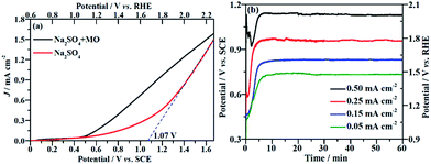 |
| | Fig. 3 (a) Linear sweep voltammetric curves of the NF/β-Ni(OH)2 electrode in a 0.05 mol L−1 Na2SO4 electrolyte with and without 0.2 mmol L−1 MO. Potential sweep rate: 10 mV s−1. (b) Chronopotentiometric potential–time curves at different current densities. | |
Fig. 3a also shows that when MO was present in the solution, an obvious oxidation J was observed with an onset potential of ca. 0.50 V vs. SCE. By comparing the LSV curves with and without MO, it is safe to conclude that the electrochemical oxidation of MO commenced at 0.50 V vs. SCE. This result implies that the NF/β-Ni(OH)2 electrode exhibited a remarkable catalytic activity toward MO oxidation even in the low potential region from 0.50 V to 1.07 V vs. SCE. Ideally, during electrochemical degradation, the applied potential should remain below the water oxidation onset potential (1.07 V vs. SCE) to reduce the competition of the OER and so improve the current efficiency and energy efficiency.7 Fig. 3a clearly shows that the oxidation current in the low potential region (from 0.50 V to 1.07 V vs. SCE) mainly came from the oxidation of MO because the OER did not occur significantly in this potential region. Therefore, it is possible to electrochemically degrade MO on the NF/β-Ni(OH)2 anode while avoiding the occurrence of the OER in the low potential region.
The EOD of organic pollutants is usually carried out at a constant J3 because a constant J means a fixed electrochemical reaction rate, which is convenient for industrial application. Fig. 3b shows the potential response with time during the galvanostatic measurements at different J values of 0.05, 0.15, 0.25 and 0.50 mA cm−2. As shown in Fig. 3b, the smaller the applied value of J is, the lower the stable potential will be. When J is less than or equal to 0.25 mA cm−2, the stable potential is lower than 1.07 V, implying that water oxidation does not significantly occur at these current densities. However, at a J value of 0.50 mA cm−2, the stable potential (ca. 1.10 V) falls into the region in which the OER starts at the NF/β-Ni(OH)2 anode. In fact, the slow but obvious formation and evolution of O2 bubbles was observed during galvanostatic degradation at 0.50 mA cm−2. Therefore, in this work, we employed three small constant current densities of 0.05, 0.15 and 0.25 mA cm−2 to avoid the OER and to demonstrate the high electrocatalytic activity of the NF/β-Ni(OH)2 anode toward the degradation of MO with very low energy consumption.
3.3 Electrochemical oxidative degradation of MO at constant current density
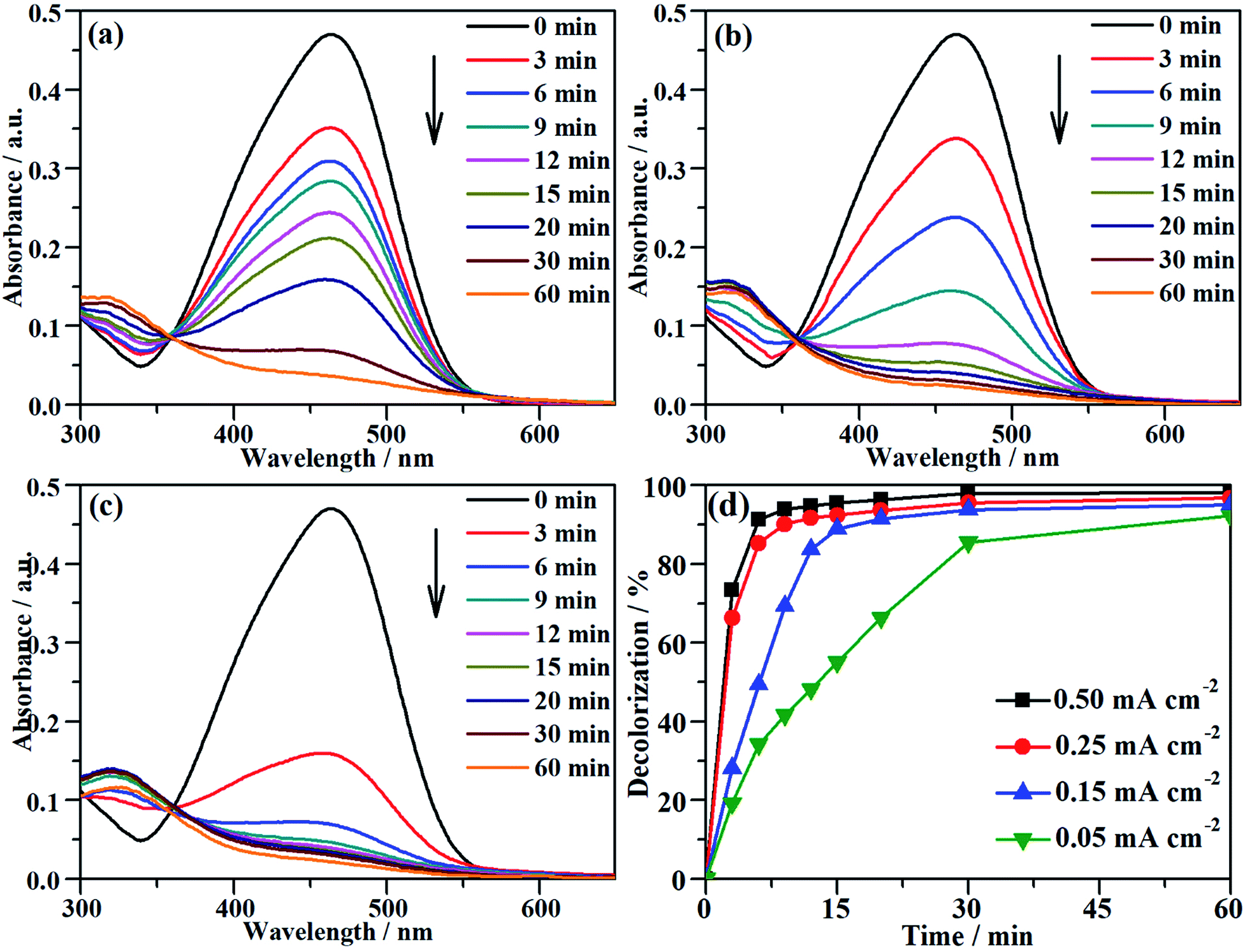
The characteristic absorption peak of MO that is attributed to the conjugated structure of azo benzene is located at 464 nm in the UV-vis spectrum.43 During the galvanostatic degradation, the decolorization of MO was monitored using UV-vis spectroscopy because the intensity of the absorption peak represents the concentration of MO. Fig. 4a–c present the evolution of the UV-vis spectra as a function of time during EOD at a constant current density of 0.05, 0.15 and 0.25 mA cm−2, respectively. The absorption peak of MO decreased with degradation time at all current densities, and total decolorization was achieved within 60 min even at a current density as low as 0.05 mA cm−2. The decolorization efficiency at any time can be calculated from eqn (2) using the absorbance at λ = 464 nm in the UV-vis spectra. Fig. 4d shows the variation of the decolorization efficiency as a function of degradation time. The electrochemical decolorization rate depended significantly on the applied current density J, and a higher value of applied J resulted in a larger decolorization rate. With a constant J of 0.05 mA cm−2, it took only 30 min to achieve 85% decolorization efficiency, whereas it took 12 min to reach the same efficiency with a constant J of 0.15 mA cm−2. Surprisingly, it took only 6 min when the applied J was 0.25 mA cm−2. Fig. 4d also demonstrates that total decolorization could be completed within 30 min as long as the applied J was higher than 0.15 mA cm−2. This result reveals that the NF/β-Ni(OH)2 anode had a high catalytic activity toward the electrooxidative decolorization of MO. It should be pointed out herein that, due to the fast decolorization at 0.25 mA cm−2, there is little room to further improve the decolorization rate by increasing the current density. In fact, as shown in Fig. 4d, when J was increased to 0.50 mA cm−2, it still took ca. 5 min to achieve a decolorization efficiency of 85%. Moreover, as shown in Fig. 3, when the applied J was increased to 0.50 mA cm−2, the competing side reaction (OER) occurred significantly, which inevitably increased the unnecessary energy consumption. Therefore, in this work, we employed 0.25 mA cm−2 as the highest J for the following experiments: galvanostatic degradation, recycling tests, stability measurements, and mechanism analyzing experiments as well.
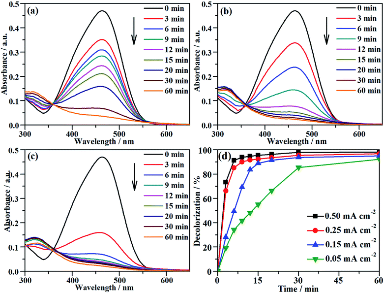 |
| | Fig. 4 The variation of the UV-vis spectra of the MO solution as a function of time during galvanostatic degradation at the different current densities of (a) 0.05 mA cm−2, (b) 0.15 mA cm−2 and (c) 0.25 mA cm−2. (d) Dependence of decolorization on time during EOD at different current densities. The galvanostatic degradation was conducted in a 0.2 mmol L−1 MO solution containing 0.05 mol L−1 Na2SO4 at room temperature. | |
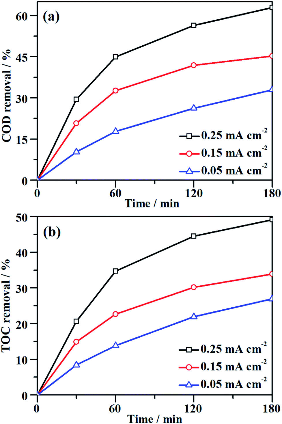
Although the decolorization efficiency is one of the key parameters for evaluating the degradation of dye pollutants, it cannot be taken as evidence of mineralization because decolorization only relates to the cleavage of the conjugated structure. To further investigate the capability for mineralization, the COD and TOC levels of the MO solution were monitored and the results are shown in Fig. 5. Under a certain current density, both COD and TOC removal continue to increase over time, demonstrating that the NF/β-Ni(OH)2 electrode is capable of not only decolorizing but also mineralizing MO. As the current density was increased from 0.05 to 0.25 mA cm−2, both COD and TOC removal in the same time interval increased. After 3 h of degradation at 0.25 mA cm−2, 63.0% COD removal and 49.1% TOC removal were achieved. According to eqn (3), the calculated current efficiency after 0.5 h and 3 h was 44.9% and 26.4%, respectively. These values are relatively high for electrooxidation degradation, indicating the superior activity of the NF/β-Ni(OH)2 electrode. These results illustrate that the NF/β-Ni(OH)2 electrode is highly active for the mineralization of MO even in the low potential region.
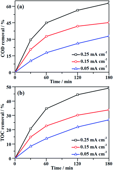 |
| | Fig. 5 Variation of (a) COD removal and (b) TOC removal as a function of time during galvanostatic degradation at different current densities. The galvanostatic degradation was conducted in a 0.2 mmol L−1 MO solution containing 0.05 mol L−1 Na2SO4 at room temperature. | |
3.4 Stability and recyclability of the NF/β-Ni(OH)2 electrode for EOD
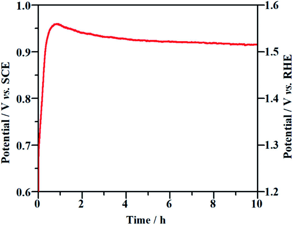
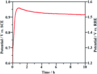
Long-term durability and recyclability are two crucial parameters that determine the performance of the NF/β-Ni(OH)2 electrode in practical applications. To examine the stability of the electrode during the electrocatalytic process, EOD measurements were continuously carried out at 0.25 mA cm−2 for 10 h and Fig. 6 shows the corresponding potential–time curve. As is well known, when the activity of an anode decays during galvanostatic oxidation, the stable potential will increase with reaction time. As shown in Fig. 6, during the entire galvanostatic degradation, the potential was stabilized at ca. 0.93 V vs. SCE. The SEM images of NF/β-Ni(OH)2 after EOD are presented in Fig. 7. Compared with NF/β-Ni(OH)2 before EOD as shown in Fig. 1c and d, both low and high magnification SEM images indicate clearly that after 3 hours of degradation, the morphology does not change and the spindle-like nanorods remain intact, indicating that NF/β-Ni(OH)2 had an excellent stability for EOD. Fig. 8a shows the COD removal of MO in four consecutive runs of galvanostatic degradation that were conducted at 0.25 mA cm−2 each for 3 h. The potential–time responses of the four degradation cycles are shown in Fig. 8b. The COD removal remained nearly unchanged even after four reaction cycles (Fig. 8a), and the stable potentials of each EOD cycle were quite similar to each other (Fig. 8b). These results provide solid evidence that the NF/β-Ni(OH)2 electrode has a good recyclability for the EOD of MO.
 |
| | Fig. 6 Chronopotentiometric potential–time curve of the NF/β-Ni(OH)2 electrode at a current density of 0.25 mA cm−2. | |
 |
| | Fig. 7 Low (a) and high (b) magnification SEM images of NF/β-Ni(OH)2 after electrooxidative degradation. | |
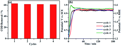 |
| | Fig. 8 Recyclability of the NF/β-Ni(OH)2 electrode for the galvanostatic degradation of MO. (a) Percentage of COD removal of MO for four consecutive degradation cycles. (b) Corresponding potential–time response for each degradation cycle. | |
Table 1 Percentage of COD and TOC removal and the normalized energy consumption during EOD of dye solutions using different electrodes
| Electrodes |
Dye |
J (mA cm−2) |
Electrolysis time (h) |
COD removal (%) |
TOC removal (%) |
Energy Cost (kW h m−3) |
ECTOC (kW h (kg COD)−1) |
Ref. |
| Current (A). |
| NF/β-Ni(OH)2 |
Methyl orange |
0.25 |
3 |
63.0 |
49.1 |
1.21 |
22.2 |
This work |
| Ti4O7 |
DFWW |
8 |
2 |
68.8 |
— |
32 |
248.7 |
22 |
| PbO2 |
Methyl orange |
0.6a |
4 |
— |
60 |
34.7 |
— |
46 |
| PbO2 |
Basic yellow 2 |
50 |
4 |
95 |
— |
26.13 |
183 |
47 |
| BDD |
Methyl orange |
31 |
2.3 |
— |
60.3 |
7.66 |
— |
48 |
| BDD |
Real wastewater |
60 |
15 |
99 |
— |
300 |
466 |
49 |
| BDD |
Basic yellow 2 |
50 |
1.5 |
95 |
— |
11.33 |
79.5 |
47 |
| Nb/BDD |
Real wastewater |
5 |
5 |
93 |
— |
30 |
108 |
50 |
| Si/BDD |
Direct black 22 |
30 |
— |
65 |
— |
115 |
816 |
51 |
| Pt |
Methyl red |
60 |
2.5 |
— |
25 |
56.4 |
— |
52 |
| Ti/Pt |
Methylene blue |
50 |
6 |
75 |
— |
33.6 |
279 |
38 |
| Ti/Ru0.3Ti0.7O2 |
Methyl red |
30 |
2.5 |
— |
100 |
11 |
— |
53 |
| GAC/ATOT |
Rhodamine B |
60 |
1 |
65 |
— |
39 |
400 |
54 |
| DSA |
Real wastewater |
75 |
3 |
55 |
— |
— |
— |
55 |
| Ti–Pt/β-PbO2 |
Real wastewater |
75 |
3 |
90 |
— |
50 |
101 |
55 |
| Ti/RuOxTiOx |
Red CR |
40 |
15 |
95 |
— |
127.99 |
— |
56 |
| Ti/IrO2–RuO2 |
Real wastewater |
25 |
2 |
32.4 |
— |
— |
48 |
57 |
3.5 Energy consumption analysis
Energy consumption is an essential parameter to assess the viability of an electrochemical method for the degradation of organic pollutants in the viewpoint of industrial applications. The energy consumption of EOD can be calculated out on the basis of eqn (3). In this work, when EOD was conducted at 0.25 mA cm2 for 3 h, 63% COD removal were obtained on the NF/β-Ni(OH)2 electrode at the expense of an energy consumption of only 1.21 kW h m−3. To rule out the effect of the organic pollutant amount on the energy consumption and to make an easy comparison with the results reported in literature, we normalized energy consumption by COD removal (NECCOD) according to eqn (4). The values of NECCOD, COD and TOC removal efficiencies obtained on the NF/β-Ni(OH)2 electrode in this work and on other anode materials reported in literature were listed in Table 1 for comparison. By using the NF/β-Ni(OH)2 anode, we obtained an NECCOD value of 22.2 kW h (kg COD)−1, which is remarkably smaller than those reported in literature. The lowest energy consumption per unit mass of COD or TOC was ascribed to the high electrocatalytic activity of NF/β-Ni(OH)2 for MO oxidation at low potential region. It should be pointed out herein that, at high potential region, some of the catalysts such as BDD exhibited a higher activity toward degradation of organic dyes than the NF/β-Ni(OH)2 electrode.44,45 However, considering the low cost and high energy efficiency, our NF/β-Ni(OH)2 electrode is still highly competitive to other electrodes for EOD. In the light of results above, NF/β-Ni(OH)2 may become a promising candidate electrode material, whose electrochemical properties make it more cost effective than BDD and more environmentally friendly than PbO2 and SnO2 based electrodes.
3.6 Mechanism of the electrooxidative degradation of MO on the NF/β-Ni(OH)2 electrode
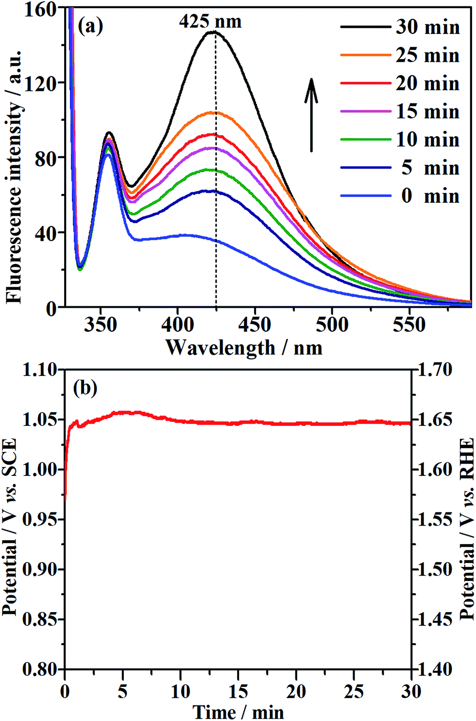
The EOD of organic compounds involves the following two routes: direct oxidation at the electrode surface, and indirect oxidation in homogeneous solution by hydroxyl radicals (˙OH) that are generated on the electrode.1,16 To determine which of the above routes is the main mechanism on the NF/β-Ni(OH)2 anode, we added a hydroxyl radical scavenger to capture the electrochemically generated ˙OH. In this work, terephthalic acid was employed as the hydroxyl radical scavenger because it combines rapidly with ˙OH to form a highly fluorescent product (2-hydroxyterephthalic acid).58 Therefore, the electrochemically generated ˙OH could be directly detected using a fluorescence technique and the concentration of ˙OH could be reflected by the intensity of the fluorescence emission peak of 2-hydroxyterephthalic acid at 425 nm.58 Fig. 9a shows the evolution of the fluorescence emission spectra of the 0.05 mol L−1 Na2SO4 solution (pH 7) containing 5 × 10⁻⁴ mol L−1 terephthalic acid during galvanostatic oxidation at 0.25 mA cm−2. It is clearly seen that the intensity of the fluorescence emission peak at 425 nm increases with increasing reaction time, which implies that ˙OH was continuously produced during the galvanostatic oxidation. Fig. 9b shows the potential response with time during galvanostatic oxidation at 0.25 mA cm−2. It is clearly seen from Fig. 9b that the stable potential is only ca. 1.04 V vs. SCE, which falls into the low potential region (<1.07 V vs. SCE) discussed in Section 3.2. Fig. 9a and b show solid evidence that, even in low potential regions (<1.07 V vs. SCE), the NF/β-Ni(OH)2 anode could generate a large amount of hydroxyl radicals, which could diffuse into the bulk of the solution and be captured by terephthalic acid. We believe that this is the origin of why the NF/β-Ni(OH)2 anode exhibits high activity toward EOD at low potential.
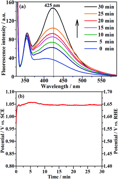 |
| | Fig. 9 (a) Fluorescence spectral changes observed during galvanostatic oxidation at a current density of 0.25 mA cm−2 in 0.05 mol L−1 Na2SO4 (pH 7) containing 5 × 10⁻⁴ mol L−1 terephthalic acid at room temperature. (b) The corresponding potential–time curve during galvanostatic oxidation. | |
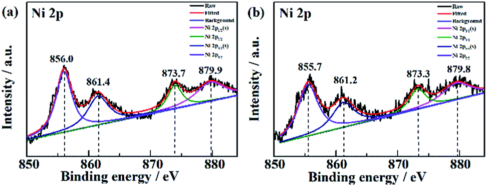
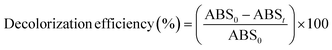
The XPS data of Ni in NF/β-Ni(OH)2 before and after electrooxidation of the dye were obtained and the Ni 2p high-resolution spectra are presented in Fig. 10. In Fig. 10a the two major peaks at 856.0 eV and 873.7 eV correspond to Ni 2p3/2 and Ni 2p1/2, respectively, along with the satellite peaks at 861.4 eV and 879.9 eV, all of which are consistent with previous reports40 and confirm that pure Ni(OH)2 was synthesized on the surface. Fig. 10b shows the XPS data after 3 h of electrooxidation and we can see that the spectrum has barely changed with only a shift of ∼0.3 eV due to the long-term degradation. No peaks of Ni3+ or Ni4+ were detected using XPS. This result is not surprising because the generated high valence state species of Ni are highly active, so once formed they will instantly react with H2O to produce hydroxy radicals and oxidize the organic pollutants. According to the above discussion, it is safe to conclude that indirect oxidation via the electrochemically generated hydroxyl radicals is the main mechanism for the EOD of MO. The NF/β-Ni(OH)2 electrocatalyst plays a key role in the EOD of azo-dye, and the main mechanism is as follows. First, β-Ni(OH)2 is electrochemically oxidized to high valence state species such as NiO(OH) or NiO(OH)2 at high positive potential in aqueous solution. Second, the generated Ni(III) and Ni(IV) species that are highly active react with H2O to produce hydroxy radicals. Finally, the highly oxidative hydroxy radicals attack and degrade the azo-dye molecules. The reactions are as follows:
| β-Ni(OH)2 − e− → NiO(OH) + H+ |
| β-Ni(OH)2 + H2O − 2e− → NiO(OH)2 + 2H+ |
| NiO(OH) + H2O → β-Ni(OH)2 + ˙OH |
| NiO(OH)2 + H2O → β-Ni(OH)2 + 2˙OH |
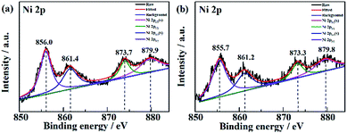 |
| | Fig. 10 High resolution Ni 2p spectra of NF/β-Ni(OH)2 (a) before and (b) after electrooxidation of a dye. | |
4. Conclusions
In summary, the nickel-foam-supported β-Ni(OH)2 electrode was successfully prepared via a facile hydrothermal method in H2O2 solution, and the resulting NF/β-Ni(OH)2 electrode had a three-dimensional porous structure with the nickel foam being coated with a thin but complete and dense film of β-Ni(OH)2. The NF/β-Ni(OH)2 electrode exhibited high activity toward the electrooxidative degradation of MO in the low potential region (<1.07 V vs. SCE), in which the competing side reaction (water oxidation) did not occur significantly. This property ensured that the NF/β-Ni(OH)2 electrode was energy-efficient for the EOD of MO. During galvanostatic degradation at 0.25 mA cm−2, the decolorization of MO was complete within 30 min. The COD and TOC removals after EOD for 3 h were 63.0% and 49.1%, respectively, with a normalized energy consumption of 22.2 kW h (kg COD)−1. This value is not only the lowest but also just a fraction of (or even one-tenth of) the values reported in the literature. The NF/β-Ni(OH)2 anode showed an excellent stability for EOD, with no sign of activity decay during 10 h of continuous galvanostatic degradation. In addition, the NF/β-Ni(OH)2 electrode also exhibited a good recyclability for EOD and the COD removal remained almost unchanged after four consecutive cycles of degradation. The mechanism of the EOD on the NF/β-Ni(OH)2 electrode was demonstrated to be the homogeneous indirect oxidation of MO by hydroxyl radicals, which were electrochemically generated during galvanostatic degradation. Owing to its high activity at low potential, high energy efficiency, good stability, and excellent recyclability, NF/β-Ni(OH)2 is a highly competitive anode material for EOD in large scale industrial applications. In addition, this work makes the following combined EOD strategy possible: a long but energy-efficient EOD using NF/β-Ni(OH)2, followed by a short but COD-removal (or TOC-removal) efficient EOD to balance the removal efficiency and energy consumption. Future work to combine this energy-efficient NF/β-Ni(OH)2 anode with a highly TOC removing anode is on the way.
Conflicts of interest
There are no conflicts to declare.
Acknowledgements
We gratefully acknowledge the financial support of this work by the National Natural Science Foundation of China (NSFC 51672017 and 21173016), Beijing Natural Science Foundation (2142020 and 2151001), and China-Romania Inter-Governmental Science & Technology Cooperation Project (42-26).
Notes and references
- C. A. Martinez-Huitle and S. Ferro, Chem. Soc. Rev., 2006, 35(12), 1324–1340 RSC.
- E. Forgacs, T. Cserhati and G. Oros, Environ. Int., 2004, 30(7), 953–971 CrossRef PubMed.
- C. A. Martínez-Huitle and E. Brillas, Appl. Catal., B, 2009, 87(3–4), 105–145 CrossRef.
- G. TimRobinson and RogerMarchant, PoonamNigam, Bioresour. Technol., 2001, 77(3), 247–255 CrossRef.
- S. Raghu and C. Ahmed Basha, J. Hazard. Mater., 2007, 149(2), 324–330 CrossRef PubMed.
- N. Daneshvar, H. A. Sorkhabi and M. B. Kasiri, J. Hazard. Mater., 2004, 112(1–2), 55–62 CrossRef PubMed.
- E. Brillas and C. A. Martínez-Huitle, Appl. Catal., B, 2015, 166–167, 603–643 CrossRef.
- W. H. Scottm Arnold and R. . Harris, Environ. Sci. Technol., 1995, 29, 2083–2089 CrossRef PubMed.
- C. W. M. Wei Chu, Water Res., 2000, 34, 3153–3160 CrossRef.
- J.-M. Herrmann, Catal. Today, 1999, 53, 115–129 CrossRef.
- E. L. Dionissios Mantzavinosm, M. Sahibzada, A. G. Livingstonm and I. S. Metcalfe, Water Res., 2000, 34, 1620–1628 CrossRef.
- C. B. a. G. C. Marco Panizza, Water Res., 2000, 34, 2601–2605 CrossRef.
- G. Chen, Sep. Purif. Technol., 2004, 38(1), 11–41 CrossRef.
- X.-f. Lü, H.-r. Ma, Q. Zhang and K. Du, Res. Chem. Intermed., 2012, 39(9), 4189–4203 CrossRef.
- X. Yu, M. Zhou, Y. Hu, K. Groenen Serrano and F. Yu, Environ. Sci. Pollut. Res., 2014, 21(14), 8417–8431 CrossRef PubMed.
- C. Comninellis, Electrochim. Acta, 1994, 39, 11–12 CrossRef.
- B. P. Chaplin, Environ. Sci.: Processes Impacts, 2014, 16(6), 1182–1203 Search PubMed.
- X. C. Guohua Zhao, M. Liu, P. Li, Y. Zhang, T. Cao, H. Li, Y. Lei and L. Liu, Environ. Sci. Technol., 2009, 43, 1480–1486 CrossRef.
- X. Li, D. Pletcher and F. C. Walsh, Chem. Soc. Rev., 2011, 40(7), 3879–3894 RSC.
- H. C. a. D. Johnson, J. Electrochem. Soc., 1990, 137, 10 CrossRef.
- J. M. Xu, L. Li, S. Wang, H. L. Ding, Y. X. Zhang and G. H. Li, CrystEngComm, 2013, 15(17), 3296 RSC.
- S. You, B. Liu, Y. Gao, Y. Wang, C. Y. Tang, Y. Huang and N. Ren, Electrochim. Acta, 2016, 214, 326–335 CrossRef.
- E. Brillas, B. Boye, I. Sirés, J. A. Garrido, R. M. a. Rodríguez, C. Arias, P.-L. s. Cabot and C. Comninellis, Electrochim. Acta, 2004, 49(25), 4487–4496 CrossRef.
- Y. Miao, L. Ouyang, S. Zhou, L. Xu, Z. Yang, M. Xiao and R. Ouyang, Biosens. Bioelectron., 2014, 53, 428–439 CrossRef PubMed.
- G.-F. Chen, T. Y. Ma, Z.-Q. Liu, N. Li, Y.-Z. Su, K. Davey and S.-Z. Qiao, Adv. Funct. Mater., 2016, 26(19), 3314–3323 CrossRef.
- D. K. Bediako, Y. Surendranath and D. G. Nocera, J. Am. Chem. Soc., 2013, 135(9), 3662–3674 CrossRef PubMed.
- W. Zhu, X. Yue, W. Zhang, S. Yu, Y. Zhang, J. Wang and J. Wang, Chem. Commun., 2016, 52, 1486–1489 RSC.
- Y. H. Wang, K. Y. Chan, X. Y. Li and S. K. So, Chemosphere, 2006, 65(7), 1087–1093 CrossRef PubMed.
- G. I. Cárdenas-Jirón and C. Berríos, Int. J. Quantum Chem., 2008, 108(13), 2586–2594 CrossRef.
- Z. Yue, S. Yao, Y. Li, W. Zhu, W. Zhang, R. Wang, J. Wang, L. Huang, D. Zhao and J. Wang, Electrochim. Acta, 2018, 268, 211–217 CrossRef.
- W. S. Cardoso, V. L. N. Dias, W. M. Costa, I. de Araujo Rodrigues, E. P. Marques, A. G. Sousa, J. Boaventura, C. W. B. Bezerra, C. Song, H. Liu, J. Zhang and A. L. B. Marques, J. Appl. Electrochem., 2008, 39(1), 55–64 CrossRef.
- M. Jafarian, M. Babaee, F. Gobal and M. G. Mahjani, J. Electroanal. Chem., 2011, 652(1–2), 8–12 CrossRef.
- G. P. Anipsitakis and D. D. Dionysiou, Environ. Sci. Technol., 2004, 38, 3705–3712 CrossRef PubMed.
- W. Zhu, R. Zhang, F. Qu, A. M. Asiri and X. Sun, ChemCatChem, 2017, 9, 1721–1743 CrossRef.
- F. Zhang, Y. J. Liu, Q. H. Liu, Q. Li, H. Li, X. Y. Cai and Y. D. Wang, Mater. Technol., 2013, 28(6), 310–315 CrossRef.
- S. R. Yousefi, D. Ghanbari, M. Salavati-Niasari and M. Hassanpour, J. Mater. Sci.: Mater. Electron., 2015, 27(2), 1244–1253 CrossRef.
- Z. Liu, Q. Su, P. Diao and F. Li, A Composite of Pyrrole-Doped, ChemElectroChem, 2017, 4(9), 2260–2268 CrossRef.
- G. R. de Oliveira, N. S. Fernandes, J. V. d. Melo, D. R. da Silva, C. Urgeghe and C. A. Martínez-Huitle, Chem. Eng. J., 2011, 168(1), 208–214 CrossRef.
- E. J. Ruiz, C. Arias, E. Brillas, A. Hernandez-Ramirez and J. M. Peralta-Hernandez, Chemosphere, 2011, 82(4), 495–501 CrossRef PubMed.
- L. Li, J. Xu, J. Lei, J. Zhang, F. McLarnon, Z. Wei, N. Li and F. Pan, J. Mater. Chem. A, 2015, 3(5), 1953–1960 Search PubMed.
- G. Xu, Z. Xu, Z. Shi, L. Pei, S. Yan, Z. Gu and Z. Zou, Silicon, ChemSusChem, 2017, 10(14), 2897–2903 CrossRef PubMed.
- Y. Zhang, B. Cui, Z. Qin, H. Lin and J. Li, Nanoscale, 2013, 5(15), 6826–6833 RSC.
- X. Li, X. Li, W. Yang, X. Chen, W. Li, B. Luo and K. Wang, Electrochim. Acta, 2014, 146, 15–22 CrossRef.
- C. Zhang, J. Wang, H. Zhou, D. Fu and Z. Gu, Chem. Eng. J., 2010, 161(1–2), 93–98 Search PubMed.
- F. L. Migliorini, N. A. Braga, S. A. Alves, M. R. Lanza, M. R. Baldan and N. G. Ferreira, J. Hazard. Mater., 2011, 192(3), 1683–1689 CrossRef PubMed.
- G. Ramírez, F. J. Recio, P. Herrasti, C. Ponce-de-León and I. Sirés, Electrochim. Acta, 2016, 204, 9–17 CrossRef.
- E. Hmani, Y. Samet and R. Abdelhédi, Diamond Relat. Mater., 2012, 30, 1–8 CrossRef.
- C. Ramírez, A. Saldaña, B. Hernández, R. Acero, R. Guerra, S. Garcia-Segura, E. Brillas and J. M. Peralta-Hernández, J. Ind. Eng. Chem., 2013, 19(2), 571–579 CrossRef.
- C. A. Martínez-Huitle, E. V. dos Santos, D. M. de Araújo and M. Panizza, J. Electroanal. Chem., 2012, 674, 103–107 CrossRef.
- J. M. Aquino, G. F. Pereira, R. C. Rocha-Filho, N. Bocchi and S. R. Biaggio, J. Hazard. Mater., 2011, 192(3), 1275–1282 CrossRef PubMed.
- J. M. Aquino, M. A. Rodrigo, R. C. Rocha-Filho, C. Sáez and P. Cañizares, Chem. Eng. J., 2012, 184, 221–227 CrossRef.
- M. G. Tavares, L. V. A. da Silva, A. M. Sales Solano, J. Tonholo, C. A. Martínez-Huitle and C. L. P. S. Zanta, Chem. Eng. J., 2012, 204–206, 141–150 CrossRef.
- C. C. d. O. Morais, A. J. C. da Silva, M. B. Ferreira, D. M. de Araújo, C. L. P. S. Zanta and S. S. L. Castro, Electrocatalysis, 2013, 4(4), 312–319 CrossRef.
- X. Li, Y. Wu, W. Zhu, F. Xue, Y. Qian and C. Wang, Electrochim. Acta, 2016, 220, 276–284 CrossRef.
- J. M. Aquino, R. C. Rocha-Filho, L. A. M. Ruotolo, N. Bocchi and S. R. Biaggio, Chem. Eng. J., 2014, 251, 138–145 CrossRef.
- M. H. Isa, Desalin. Water Treat., 2013, 53(8), 2260–2265 CrossRef.
- M. Zhou, L. Liu, Y. Jiao, Q. Wang and Q. Tan, Desalination, 2011, 277(1–3), 201–206 CrossRef.
- A. Fujishimaa, K.-i. Ishibashi, T. Watanabe and K. Hashimoto, J. Photochem. Photobiol., A, 2000, 134, 139–142 CrossRef.
Footnote |
| † Electronic supplementary information (ESI) available. See DOI: 10.1039/c8ra03039a |
|
| This journal is © The Royal Society of Chemistry 2018 |
Click here to see how this site uses Cookies. View our privacy policy here. 
 Open Access Article
 This Open Access Article is licensed under a Creative Commons Attribution-Non Commercial 3.0 Unported Licence
 a,
Peng Diao
a,
Peng Diao