 Open Access Article
On how ancillary ligand substitution affects the charge carrier dynamics in dye-sensitized solar cells†
Hashem Shahroosvand *,
Saeid Abaspour,
Babak Pashaei and
Babak Nemati Bideh
Group for Molecular Engineering of Advanced Functional Materials (GMA), Chemistry Department, University of Zanjan, Zanjan, Iran. E-mail: shahroos@znu.ac.ir
First published on 29th May 2018
Abstract
With respect to N3, a champion sensitizer in dye-sensitized solar cells (DSSCs), S3 which contained a phenTz (1,10-phenanthroline 5-tetrazole) ancillary ligand showed outstanding improvements in molar extinction coefficient (ε) from 10![[thin space (1/6-em)]](https://www.rsc.org/images/entities/char_2009.gif) 681.8 to 12
681.8 to 12![[thin space (1/6-em)]](https://www.rsc.org/images/entities/char_2009.gif) 954.5 M cm−1 as well as 0.92% and 0.9% increases in power conversion efficiency (PCE) and incident photon-to-electron conversion efficiency (IPCE), reaching 8.46% and 76.5%, respectively. To find the origin of the high performance of the DSSC based on a phenTz ancillary ligand, transient absorption spectroscopy (TA) was carried out and indicated that the rate of the regeneration reaction is about 100 times faster than the rate of recombination with the dye which is very exciting and surely a good reason to promote the phenTz ligand as a promising ancillary ligand in DSSCs.
954.5 M cm−1 as well as 0.92% and 0.9% increases in power conversion efficiency (PCE) and incident photon-to-electron conversion efficiency (IPCE), reaching 8.46% and 76.5%, respectively. To find the origin of the high performance of the DSSC based on a phenTz ancillary ligand, transient absorption spectroscopy (TA) was carried out and indicated that the rate of the regeneration reaction is about 100 times faster than the rate of recombination with the dye which is very exciting and surely a good reason to promote the phenTz ligand as a promising ancillary ligand in DSSCs.
Dye-sensitized solar cells (DSSCs) are still one of the most attractive devices for converting solar energy to electrical energy,1 achieving 11.9 ± 0.4% and 11.2 ± 0.3% for the record power conversation efficiency (PCE) values for DSSCs and solid-state DSSCs, respectively.2 However, the recent remarkable progress due to perovskite solar cells (PSCs) on enhancing PCE values, which have reached above 22%,3 demonstrates an alternative candidate to replace DSSCs. However, the very low stability of PSCs under normal conditions and the high toxicity of the lead in the perovskite component result in an ambiguous future for their commercialization and development in the industry.4 Therefore, the higher stability of DSSCs compared to that of PSCs is an outstanding property which has attracted great interest among scientists.5 However, there are very much still issues of fundamental understanding for both DSSCs and PSCs, for which theoreticians have to come in. In addition, Michael Grätzel correctly stated, “So, fundamentals are key, and that holds for both the DSSC technology and PSCs because we want to get to new formulations with reduced lead and some alternative substituents less compromising for the environment. So, working on fundamentals is actually extremely important for both the DSSC and PSC sides”.6
Consequently, most research on DSSCs has been concerned with the exploring of the dyes and electrolytes as well as the consistency between them.7 In this framework, an ancillary ligand component of a dye plays a key role in enhancing the PCE via different approaches including increasing the molar absorption coefficient, extending the light harvesting and so on.8 Since the design of the ancillary ligand around the metal cores is a key factor for an efficient electron transfer process in DSSCs,9 the introduction of aromatic rings containing multiple nitrogen donor atoms such as imidazolyl,10 triazolyl11 or pyrazolyl12 rings in the backbone of the polypyridyl ligand, allowed the modulation of the spectroscopic and redox properties through the tuning of the HOMO–LUMO gap of the resulting complexes.13 Tetrazole is an interesting ligand which is extensively used in different applications such as in organic light emitting diodes (OLEDs),14 light emitting electrochemical cells (LEECs),15 DSSCs,16 and so on. The strong electron-withdrawing character of the tetrazolate ligand due to bipyridine can increase the oxidation potential of ruthenium(II) dyes containing these ligands, a useful tool for the facile regeneration of oxidized sensitizers through the presence of a redox couple.17 In addition to its utility for electron transfer properties in optoelectronic devices, the tetrazolate ligand has previously been employed to provide remarkable coordination networks with transition metals.18 However, a few tetrazole complexes were reported for use in DSSCs to date, indicating hopeful results for the promotion of this family.16 However, there are no reports on the incorporation of tetrazole coupled with a polypyridyl ligand into DSSCs so far. Here, for the first time, we employed three sensitizers based on 1,10-phenanthroline which were functionalized with a tetrazole moiety, which led to higher PCEs than the benchmark sensitizer N3.
The synthesis procedure for phenTz is simple and does not require special conditions or further purification. However, the attachment of tetrazole to a polypyridyl ligand is very rare and this pathway could open up new avenues for the synthesis of other complexes in the polypyridyl family. The synthesis procedures for the ligands and complexes are shown in Fig. 1 and explained in the ESI in Fig. S1 and S2†. The structure of the synthesized complexes is homologous to N3 and systematically comparable with it. For S1, one phenTz replaced the NCS groups of N3, for S2, one phenTz and one bpy replaced the NCS groups and a dicarboxylic bipyridine (dcbpy) and for S3, one phenTz replaced one dcbpy. Therefore, our actual aim in this work is to modify the structure of N3 with a phenTz ligand.
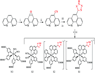 | ||
| Fig. 1 The synthesis procedures for phenTz and the S1–S3 complexes. The structure of N3 is shown for comparison. | ||
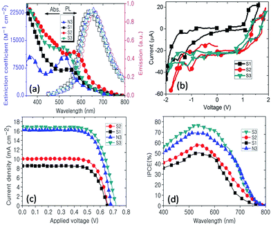
Typically, the UV-vis spectra of ruthenium polypyridyl complexes show two quite different regions: one is an intense band in the UV region which can be attributed to intra-ligand charge transfer and the other is a relatively broad band in the visible region which can be assigned to metal to ligand charge transfer (MLCT).19 The broadening and red shifting of the MLCT band in S1–S3 can be attributed to spin–orbit coupling, exhibiting a band tail which has been theoretically proven.14 The first promising evidence that tetrazole can be employed as an ancillary ligand in DSSCs is the increasing of the molar absorption coefficient (ε) for the MLCT of S2 and S3 compared to that of N3, as shown in Fig. 2a. The ε values for S1, S2, S3 and N3 are 7045.4, 11![[thin space (1/6-em)]](https://www.rsc.org/images/entities/char_2009.gif) 818.2, 12
818.2, 12![[thin space (1/6-em)]](https://www.rsc.org/images/entities/char_2009.gif) 954.5 and 10
954.5 and 10![[thin space (1/6-em)]](https://www.rsc.org/images/entities/char_2009.gif) 681.8 M cm−1, respectively, showing that the ε of S3 is 21% higher than that of N3. This property is due to the efficient light harvesting antenna, the tetrazole ancillary ligand, which is promising for enhancing the PCE. As shown in Fig. 2b, the photoluminescence (PL) spectra of the synthesized complexes are the same as N3 in the deep red region with a quantum yield of about 0.6, confirming the similarity between the ruthenium tetrazole polypyridyl family and the ruthenium polypyridyl analogues.20 The cyclic voltammetry analysis of the S1–S3 complexes also shows typical behaviour for ruthenium polypyridyl complexes including one pseudo-reversible redox half wave in the positive region due to Ru(II)/Ru(III) and some irreversible redox half waves in the negative region. The oxidation half potential of the standard N3 is about 1.10 V vs. the NHE if the dye is fully protonated,21 while the Eox values for S1–S3 are 1.22, 1.44 and 1.48 V, respectively. Therefore, we expect that S3 could better facilitate the regeneration of the oxidized dyes through the presence of the redox couple than N3 due to the stronger electron-withdrawing nature of the tetrazole ligand compared to that of bipyridyl.17
681.8 M cm−1, respectively, showing that the ε of S3 is 21% higher than that of N3. This property is due to the efficient light harvesting antenna, the tetrazole ancillary ligand, which is promising for enhancing the PCE. As shown in Fig. 2b, the photoluminescence (PL) spectra of the synthesized complexes are the same as N3 in the deep red region with a quantum yield of about 0.6, confirming the similarity between the ruthenium tetrazole polypyridyl family and the ruthenium polypyridyl analogues.20 The cyclic voltammetry analysis of the S1–S3 complexes also shows typical behaviour for ruthenium polypyridyl complexes including one pseudo-reversible redox half wave in the positive region due to Ru(II)/Ru(III) and some irreversible redox half waves in the negative region. The oxidation half potential of the standard N3 is about 1.10 V vs. the NHE if the dye is fully protonated,21 while the Eox values for S1–S3 are 1.22, 1.44 and 1.48 V, respectively. Therefore, we expect that S3 could better facilitate the regeneration of the oxidized dyes through the presence of the redox couple than N3 due to the stronger electron-withdrawing nature of the tetrazole ligand compared to that of bipyridyl.17
The obtained interesting results from UV-vis spectroscopy and its electrochemical properties make ruthenium tetrazole a good candidate for use in DSSCs. To explore the photovoltaic performance of the investigated complexes, DSSCs based on these complexes have been fabricated, as explained in the ESI (Fig. S3†). As shown in Fig. 2c, surprisingly, DSSCs based on S3 showed higher PCEs than N3, reaching 8.46% which indicates the importance of the phenTz ligand. After S3, S2 and then S1 have the highest PCEs, which are lower than that of N3. This remarkable result indicated the substitution of the ancillary ligand, for which the appropriate substitution was found in S3, where one phenTz had replaced one dcbpy in N3. To investigate the ability of the synthesized complexes to convert photons to electricity, the incident photon-to-electron conversion efficiency (IPCE) was recorded, as shown in Fig. 2d. The IPCE results confirmed the obtained results from UV-vis and I–V, showing that S3 has the best performance among the other synthesized complexes, as well as N3 (Table 1). As expected from the I–V and IPCE data, the minimum series resistance of the devices was achieved for S3 with 1.979 ohm cm−2, confirming that it was the most efficient in its family. To confirm the reproducibility of the I–V results and avoid residual data, 10 cells were fabricated for which the PCE values were close to those from the current results (ESI, Fig. S2†).
| Dye | Jsc (mA cm−2) | Voc (V) | FF (%) | η (%) | IPCE (%) | Series resistance (ohm cm−2) |
|---|---|---|---|---|---|---|
| S1 | 8.51 | 0.65 | 72.2 | 4.02 | 50.3 | 4.614 |
| S2 | 10.03 | 0.65 | 73.2 | 4.84 | 58.4 | 12.05 |
| S3 | 16.75 | 0.72 | 70.0 | 8.46 | 76.5 | 1.979 |
| N3 | 16.30 | 0.68 | 70.5 | 7.83 | 69.4 | 2.53 |
The photostability of a DSSC is very critical in evaluating the new investigated dyes for further applications. The photovoltaic performance during the test was recorded in detail. The representative variations in the photovoltaic parameters of the S1–S3 and N3-sensitized solar cells are displayed in Fig. 3. From the test period results, we conclude that the stability of the cell depends on the structure of the attached dye on the TiO2 surface, confirming the importance of the type of ancillary ligand. After the aging process, the values for the PCE remained at 88%, 68.5% and 64.6% of the initial value after 14 days of light soaking for S1–S3, respectively. In our experiment, no significant changes in the PCE of N3 were observed in the same period. The stable performance demonstrated that the S3-sensitizer on the TiO2 surface remained robust after a long time of light soaking.
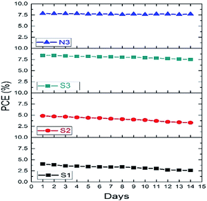 | ||
| Fig. 3 Photostability of the DSSCs based on the new dyes and N3 over time under visible light soaking. | ||
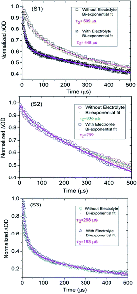
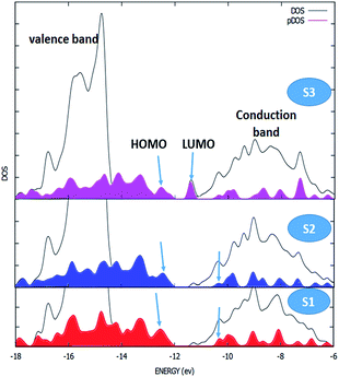
The kinetics of dye regeneration using electrolytes has attracted great interest as it is one of the crucial steps in DSSC operation.22,23 Therefore, we employed flash photolysis spectroscopy to determine the kinetics of the dye regeneration and recombination processes in the investigated DSSCs. Fig. 4 shows the transient absorption spectra of the S1–S3 dye-sensitized TiO2 films in the presence and absence of electrolyte. In the absence of electrolyte, the decays of the absorption signals reflect mostly the dynamics of the recombination of the photoinjected electrons in TiO2 with the oxidized dye. In fact, there is competition between the kinetics of the regeneration and recombination processes and under normal conditions, the kinetics of the recombination process are slower than those of regeneration, τ2 (rec) ≫ τ2 (reg), resulting in charge recombination between the oxidized dyes, and the charge-injected electrons are not an important loss in limiting device efficiency.24 As shown in Fig. 4, the DSSC based on S3 has the lowest lifetime decays, where the τ2 values for recombination (without electrolyte) and regeneration (with electrolyte) are 298 and 193 μs, indicating about 100 μs for the magnitude of the regeneration process. The values for this difference (τ2 (rec) − τ2 (reg)) for S1 and S2 are 60 and 40 μs, respectively. In agreement with the other obtained photovoltaic data, S3 has a fast dye regeneration rate and the largest difference between the rates for the dye regeneration and recombination processes. Following this, to determine the effect of the ancillary ligand on interfacial electron transfer between the TiO2 surface and the investigated complexes, ab initio DFT molecular dynamics simulations and quantum dynamics of electronic relaxation were carried out. Interestingly, this simulation describes the status of the highest occupied molecular orbital (HOMO) and the lowest unoccupied molecular orbital (LUMO) of the dyes as well as the conduction and valence bands of semiconductors. As shown in Fig. 5, the overlapping of the HOMOs and LUMOs of the dyes with the valence band and conduction band of TiO2, respectively, is clearly observed, confirming the efficient electron injection from the LUMOs of the dyes into the conduction band of TiO2. However, as shown in Fig. 5, the LUMO of S3 is more full with electrons for injection into the conduction band than those of the other S1 and S2 dyes, meaning that S3 could accomplish more efficient electron injection into TiO2 than the others. The density of states (DOS) was obtained from the extended Hückel method for the S1–S3-anatase model nanostructure. The black line shows the valance band (left) and the conduction band (right) of TiO2. The filled colored curve represents the DOS projected on the basis functions of the adsorbates S1–S3.
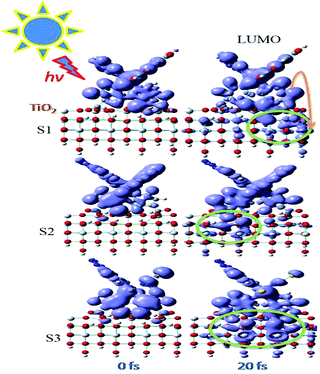
Fig. 6 shows snapshots of the electronic charge distribution at 20 fs after initiating the IET from S1–S3 attached to a pristine (101) surface. The process of sensitization in DSSCs starts with the dye attached to the TiO2 surface absorbing light, allowing the excitation of an electron from the steady state of the dye to its excited state. After that, the generated charge goes to the conduction band of TiO2 and, therefore, leads to currents in the external circuit.25 As shown in Fig. 6, after 20 fs of the excitation by light in the dyes, the amount of injected electrons from the dye into the TiO2 surface for S3 is the largest and this confirms that its electron regeneration is more effective than others. More figures for the electron injection process from the LUMO, LUMO + 1 and LUMO + 2 into the TiO2 surface over the course of 100 fs for S1–S3 are given in the ESI, Fig. S3–S12.†.
In summary, from considering that N3 is one of the champion sensitizers in DSSCs, we designed and synthesized three new heteroleptic ruthenium sensitizers, S1–S3, by incorporating tetrazole into the ancillary ligands. The sensitizer S3 containing one 4,4-dicarboxylic acid 2,2 bipyridine, and one phenTz and two NCS groups, had a better molar extinction coefficient, PCE and IPCE than N3 which was used as a benchmark sensitizer. Additionally, transition absorption studies showed that the rate of the regeneration reaction is much faster than that of recombination with the dye in the order of 100 μs. These findings provide an alternative sensitizer for improving the DSSC power conversion efficiency of ruthenium sensitizers as well as their light harvesting capability.
Conflicts of interest
There are no conflicts to declare.References
- B. Pashaei, H. Shahroosvand, M. Gratzel and M. k. Nazeeruddin, Chem. Rev., 2016, 16, 9485 CrossRef PubMed.
- M. A. Green, Y. Hishikawa and W. Warta, et al., Prog. Photovoltaics, 2017, 25, 668 Search PubMed.
- National Renewable Energy Laboratory Efficiency Chart http://www.nrel.gov/ncpv/images/efficiencychart.jpg, accessed January 2017.
- H. Tiep, Z. Ku and H. J. Fan, Adv. Energy Mater., 2016, 6, 1501420 CrossRef.
- V. A. Chiykowski, B. Lam, C. Du and C. P. Berlinguette, Chem. Commun., 2017, 53, 2547 RSC.
- F. D. Angelis and P. Kamat, ACS Energy Lett., 2017, 2, 1674 CrossRef.
- B. Pashaei, H. Shahroosvand and P. Abbasi, RSC Adv., 2015, 5, 94814 RSC.
- G. C. Vougioukalakis, A. I. Philippopoulos, T. Stergiopoulos and P. Falaras, Coord. Chem. Rev., 2011, 255, 2602 CrossRef.
- (a) V. Balzani and A. Juris, Coord. Chem. Rev., 2001, 211, 97 CrossRef; (b) J. G. Vos and J. M. Kelly, Dalton Trans., 2006, 4869 RSC.
- (a) M. J. Han, L. H. Gao, Y. Y. Lu and K. Z. Wang, J. Phys. Chem. B, 2006, 110, 2364 CrossRef PubMed; (b) M.-A. Haga, T. Takasugi, A. Tomie, M. Ishizuya, T. Yamada, M. D. Hossain and M. Inoue, Dalton Trans., 2003, 2069 RSC.
- (a) W. R. Browne, R. Hage and J. G. Vos, Coord. Chem. Rev., 2006, 250, 1653 CrossRef; (b) M. H. Klingele and S. Brooker, Coord. Chem. Rev., 2003, 241, 119 CrossRef.
- (a) N. Chanda, B. Sarkar, S. Kar, J. Fiedler, W. Kaim and G. K. Lahiri, Inorg. Chem., 2004, 43, 5128 CrossRef PubMed; (b) C. Sens, M. Rodriguez, I. Romero, A. Llobet, T. Parella and J. Benet-Buchholz, Inorg. Chem., 2003, 42, 8385 CrossRef PubMed; (c) R. H. Laye, S. M. Couchman and M. D. Ward, Inorg. Chem., 2001, 40, 4089 CrossRef PubMed.
- L.-L. Wu, C.-H. Yang, I.-W. Sun, S.-Y. Chu, P.-C. Kao and H.-H. Huang, Organometallics, 2007, 26, 2017 CrossRef.
- H. Shahroosvand, L. Najafi, A. Sousaraei, E. Mohajerani, M. Janghouri and F. Bonaccorso, J. Phys. Chem. C, 2016, 120, 2965 Search PubMed.
- H. Shahroosvand, S. Abaspour, B. Pashaei, E. Radicchi, F. D. Angelis and F. Bonaccorso, Chem. Commun., 2017, 53, 6211 RSC.
- (a) L. Zhang and J. M. Cole, ACS Appl. Mater. Interfaces, 2015, 7(6), 3427 CrossRef PubMed; (b) J. Massin, L. Ducasse, T. Toupance and C. Olivier, J. Phys. Chem. C, 2014, 118, 10677 CrossRef; (c) Y. Chi, K.-L. Wu and T.-C. Wei, Chem.–Asian J., 2015, 10, 1098 CrossRef PubMed.
- C. Dragonetti, A. Colombo, M. Magni, P. Mussini, F. Nisic, D. Roberto, R. Ugo, A. Valore, A. Valsecchi, P. Salvatori, M. GraziaLobello, F. D. Angelis and C. E. Housecroft, Inorg. Chem., 2013, 52, 10723 CrossRef PubMed.
- (a) T.-L. Hu, Y. Tao, Z. Chang and X.-H. Bu, Inorg. Chem., 2011, 50, 10994 CrossRef PubMed; (b) M. Dincă, A. F. Yu and J. R. Long, J. Am. Chem. Soc., 2006, 128, 8904 CrossRef PubMed.
- (a) D. L. Ashford, C. r. R. K. Glasson, M. R. Norris, J. J. Concepcion, S. Keinan, M. K. Brennaman, J. L. Templeton and T. J. Meyer, Inorg. Chem., 2014, 53(11), 5637 CrossRef PubMed; (b) P. A. Anderson, G. F. Strouse, J. A. Treadway, F. R. Keene and T. J. Meyer, Inorg. Chem., 1994, 33, 3863 CrossRef; (c) W. V. Yam, W. V. Lee and K. M. Siu, Inorg. Chem., 1997, 36, 2124 CrossRef PubMed; (d) B. Gholamkhass, K. Koike, N. Negishi, H. Hori and K. Takeuchi, Inorg. Chem., 2001, 40, 756 CrossRef PubMed; (e) D. P. Rillema, D. G. Taghdiri, D. S. Jones, C. D. Keller, L. A. Worl, T. J. Meyer and H. A. Levy, Inorg. Chem., 1987, 26, 578 CrossRef; (f) B. A. Albani, C. B. Durr and C. Turro, J. Phys. Chem. A, 2013, 117(50), 13885 CrossRef PubMed; (g) D. S. Seneviratne, M. J. Uddin, V. Swayambunathan, H. B. Schlegel and J. F. Endicott, Inorg. Chem., 2002, 41(6), 1502 CrossRef PubMed; (h) S. Bodige, A. S. Torres, D. J. Maloney, D. Tate, G. R. Kinsel, J. K. Walker and F. M. MacDonnell, J. Am. Chem. Soc., 1997, 119, 10364 CrossRef.
- H. Ishida, S. Tobita, Y. Hasegawa, R. Katoh and K. Nozaki, Coord. Chem. Rev., 2010, 254, 2449 CrossRef.
- M. K. Nazeeruddin, A. Kay, I. Rodicio, R. Humphry-Baker, E. Muller, P. Liska, N. Vlachopoulos and M. Gratzel, J. Am. Chem. Soc., 1993, 115, 6382 CrossRef.
- G. Boschloo and A. Hagfeldt, Chem. Phys. Lett., 2003, 370, 381 CrossRef.
- A. Hagfeldt, G. Boschloo, L. Sun, L. Kloo and H. Pettersson, Chem. Rev., 2010, 110, 6595 CrossRef PubMed.
- S. Tatay, S. A. Haque, B. O’Regan, J. R. Durrant, W. J. H. Verhees, J. M. Kroon, A. Vidal-Ferran, P. Gavin and E. Palomares, J. Mater. Chem., 2007, 17, 3037 RSC.
- (a) W. R. McNamara, R. C. Snoeberger, J. Li, J. M. Schleicher, C. W. Cady, M. Poyatos, C. A. Schmuttenmaer, R. H. Crabtree, G. W. Brudvig and V. S. Batista, J. Am. Chem. Soc., 2008, 130, 14329 CrossRef PubMed; (b) S. G. Abuabara, L. G. C. Rego and V. S. Batista, J. Am. Chem. Soc., 2005, 127, 18234 CrossRef PubMed; (c) L. G. C. Rego, S. G. Abuabara and V. S. Batista, J. Chem. Phys., 2005, 122, 154709 CrossRef PubMed; (d) L. G. C. Rego, S. G. Abuabara and V. S. Batista, Quantum Inf. Comput., 2005, 5, 318 Search PubMed; (e) L. G. C. Rego, S. G. Abuabara and V. S. Batista, J. Mod. Opt., 2006, 53, 2519 CrossRef.
Footnote |
| † Electronic supplementary information (ESI) available. See DOI: 10.1039/c8ra02968g |
| This journal is © The Royal Society of Chemistry 2018 |

