 Open Access Article
Surface modification and thermal performance of a graphene oxide/novolac epoxy composite
Shasha Lia,
Xi Liua,
Changqing Fang *a,
Nailiang Liub and
Donghong Liu*c
aFaculty of Printing, Packaging Engineering and Digital Media Technology, Xi'an University of Technology, Xi'an 710048, P. R. China. E-mail: fcqxaut@163.com
bSchool of Sciences, Xi'an University of Technology, Xi'an 710048, Shaanxi, P. R. China
cFuli Institute of Food Science, Zhejiang University, Hang Zhou 310058, P. R. China. E-mail: dhliu@zju.edu.cn
First published on 5th June 2018
Abstract
Functionalized graphene oxide (GO) was successfully modified by grafting 1,3,5-triglycidylisocyanurate (TGIC) onto the surface of GO. The modified GO was then added to a novolac epoxy composite at various volume fractions to improve the interfacial compatibility between the filler and matrix. Samples of the modified GO/novolac epoxy composite were fabricated through the hot-pressing method. Microstructural analysis revealed that the modified GO dispersed well in the matrix and formed thermal conductive pathways across the matrix. The thermal degradation temperature of 50% weight loss of the modified GO/novolac epoxy composite was 166 °C higher than that of the novolac epoxy. The data for loss factor tan![[thin space (1/6-em)]](https://www.rsc.org/images/entities/char_2009.gif) δ demonstrated that when the composite contained 36.8 wt% of modified GO, the glass transition temperature of the modified GO/novolac epoxy composite was 222 °C, which is 90 °C higher than that of the novolac epoxy. The thermal conductivity of the modified GO/novolac epoxy composite improved from 0.044 W m−1 K−1 to 1.091 W m−1 K−1. Results indicated that the incorporation of surface-modified GO into the novolac epoxy positively affects the thermal conductivity and various properties of the modified GO/novolac epoxy composite.
δ demonstrated that when the composite contained 36.8 wt% of modified GO, the glass transition temperature of the modified GO/novolac epoxy composite was 222 °C, which is 90 °C higher than that of the novolac epoxy. The thermal conductivity of the modified GO/novolac epoxy composite improved from 0.044 W m−1 K−1 to 1.091 W m−1 K−1. Results indicated that the incorporation of surface-modified GO into the novolac epoxy positively affects the thermal conductivity and various properties of the modified GO/novolac epoxy composite.
1. Introduction
Electronic products have been miniaturized and integrated as a result of improved technical requirements and changing consumer demands. Heat dissipation, however, is one of the most important problems associated with and encountered in the operation of miniaturized devices.1 Heat dissipation affects the service life of the product and user experience.2 Therefore, several studies have attempted to find effective solutions to heat dissipation. Given their good heat dissipation properties, thermal interface materials have been widely used as heat dissipaters in integrated circuits and electronic devices.3 The potential application of resin materials as heat dissipaters has recently attracted considerable attention due to their good thermal stability and excellent mechanical properties.4 However, their further application is limited by their low thermal conductivity.Resin composites with excellent thermal properties can be fabricated using polymer matrices modified with fillers that exhibit high thermal conductivity. Compared with that of metals, metal oxides, and nitrides,5 the use of carbon materials as fillers has received more research attention because of their outstanding thermal performance. Common carbon fillers include graphite, carbon black, carbon nanotubes, and diamonds. Among these fillers, graphene exhibits many advantages, such as high thermal conductivity and favorable thermal stability.6 In addition, graphene can tightly couple with matrix materials.7–9 Nevertheless, the aggregation caused by molecular interactions10–12 and compatibility between the graphene and polymer matrix13 may directly affect the performance of the graphene-modified composite. Therefore, graphene has to be subjected to surface modification, such as grafting with organic molecules.14 Surface modification is based on an initial oxidation process. After oxidation, the surface of graphene is modified with different functional groups, such as epoxy, hydroxyl, and carboxyl. Several studies have been performed on the functionalization of graphene with polar groups.
Given that the good dispersion of the filler in the matrix is an essential property of thermal conductive materials, the dispersion degree of the filler should be improved by increasing interfacial compatibility. Wan15 prepared DGEBA-functionalized graphene oxide (GO) (DGEBA-f-GO) and reported that the dispersion of DGEBA-f-GO sheets in epoxy resin is better than that of GO sheets. Increasing the grafting rate is another approach to improve interfacial compatibility. Lin16 grafted APTES onto GO sheets and then grafted maleic anhydride-grafted polyethylene onto the APTES-coated graphene with high grafting efficiency. The crystallization temperature of the modified polymer was 10 °C higher than that of the pure polymer. Notably, surface modification affected not only the interfacial property but also the mechanical property of the composite. Xia17 prepared GO-hybridized polyurethane/epoxy interpenetrating polymer networks through in situ polymerization. The prepared polymer networks exhibited good mechanical performance due to the formation of chemical bonds. Given that grafting remarkably improves interfacial compatibility, it may be worth applying in the fabrication of composites with desirable thermal conductivity.
In this study, GO was prepared through a modified Hummer's method and then grafted with ring-opened 1,3,5-triglycidylisocyanurate (TGIC) to improve its interfacial compatibility with the matrix. Novolac epoxy, a thermoplastic resin that is widely used in the production of structural parts and electrical components,18 was selected as the matrix. The modified GO is expected to provide uniform heat conduction pathways and improve the thermal performance of the modified GO/novolac epoxy composite. The curing time, curing temperature, and curing process of novolac epoxy were also explored in this study. The influence of the functionalized graphene on the property of the composites was also discussed.
2. Experimental
2.1 Materials
Natural flake graphite (NG) was supplied by Kuntai Graphite Co., Ltd. (China). Novolac epoxy was procured from Hunan JSD Materials Technology Co., LTD. TGIC was supplied by Aladdin Industrial Corporation, Shanghai, China. All other reagents, such as 98% H2SO4, KMnO4, H2O2, lactic acid, DMF, and melamine, were all of analytical grade.2.2 Preparation of GO
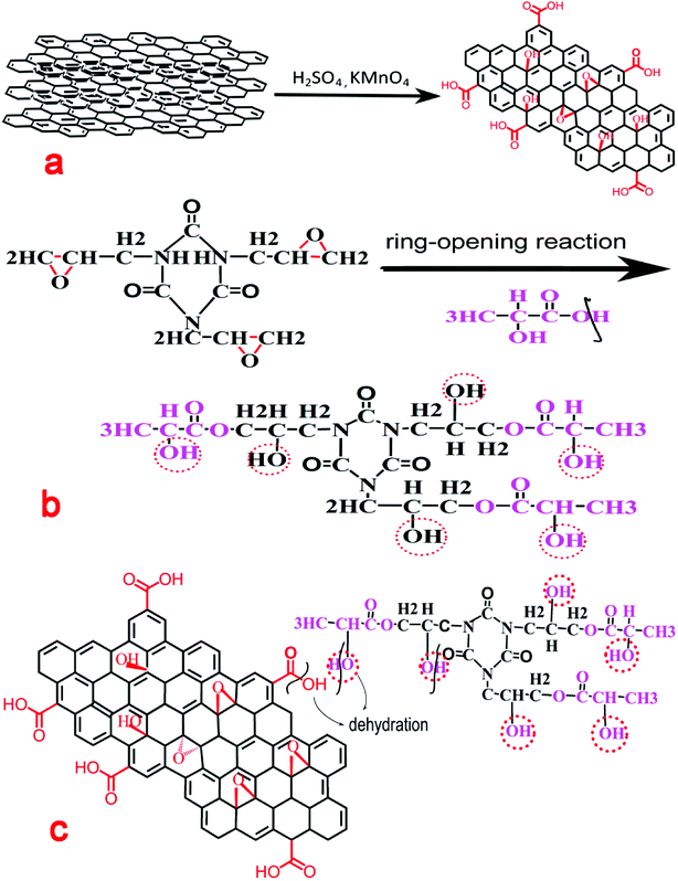
GO was synthesized through the modified Hummer's method. After oxidization, the basal spacing of GO increased. Oxygen-containing functional groups, such as epoxy, hydroxyl, and carboxyl, were then introduced on the surface of GO.19 These functional groups facilitated further surface modification. GO preparation is schematically shown in Fig. 1(a) and proceeded as follows: first, H2SO4 (35 mL) was added to NG (1.5 g) in a three-necked round-bottomed flask (150 mL) and stirred for 30 min at room temperature. KMnO4 (3 g) was added slowly to the mixture, and the mixture was stirred for at least 2 h in an ice bath and then heated to 35 °C under vigorous stirring for 30 min. Then, 150 mL deionized water was gradually added to the reaction solution, which had a temperature of 98 °C, under vigorous stirring for 15 min. Finally, 10 mL H2O2 was added to the solution, which was then stirred for 10 min. The reaction solution was centrifuged and then washed repeatedly with distilled water until the solution was almost neutral. The products were then immersed in 70% aqueous alcohol solution and treated in an ultrasonic bath for 2 to 3 days. The final product was stored until use.2.3 GO functionalization
TGIC was selected as the small organic molecule for the surface modification of GO. TGIC is a trifunctional monomer with triazine structure and contains three symmetrically distributed active epoxy groups.20,21 The epoxy groups of TGIC were opened and hydroxyl groups were introduced after the ring-opening reaction. Grafting lactic acid molecules onto the molecular chain of the ring-opened products produced another hydroxyl. GO functionalization is shown schematically in Fig. 1(b) and proceeded as follows: first, a certain amount of TGIC and lactic acid at a molar ratio of 3![[thin space (1/6-em)]](https://www.rsc.org/images/entities/char_2009.gif) :
:![[thin space (1/6-em)]](https://www.rsc.org/images/entities/char_2009.gif) 1 was mixed in a 150 mL three-necked round-bottomed flask. The reaction mixture was stirred for 8 h at 110 °C in an oil bath.22 The final product was the ring-opened TGIC.
1 was mixed in a 150 mL three-necked round-bottomed flask. The reaction mixture was stirred for 8 h at 110 °C in an oil bath.22 The final product was the ring-opened TGIC.
2.4 Preparation of grafted graphite
The surface of graphene produced oxygen-containing functional groups after oxidation. The carboxyl groups located on the GO surface will react with the hydroxyl groups of the ring-opened TGIC in a condensation reaction. Surface modification will improve interfacial compatibility between the filler and matrix. The preparation of grafted graphite is shown schematically in Fig. 1(c) and proceeded as follows: GO and ring-opened TGIC were placed in a DMF solution, mixed in a 150 mL three-necked round-bottomed flask, and stirred for 8 h in a water bath at 80 °C.23 The reaction solution was centrifuged, washed repeatedly with distilled water until the solution became almost neutral, and dried in a drying oven at 70 °C. The final product was stored until use.2.5 Preparation of the compound material
The thermally conductive composite, which is based on novolac epoxy, was prepared through the mold pressing method. Melamine was selected as the curing agent. To ensure good mixing, the filler, curing agent, and matrix were ground before mixing. First, the mixed powder was placed into the molding and cold-pressed at room temperature for 10 min. Then, the molding was transferred to an oven at 160 °C until the mixed powder turned into an elastomer. Finally, the molding was molded using a hydraulic press at 160 °C for 1 h. The weight percentage of modified GO in the composite varied from 0.58% to 36.8%. The weight percent of the curing agent was 20%. The density of GO and novolac epoxy were 0.84 and 1.2 g mL−1, respectively, and were obtained through the drainage method.2.6 Characterization
Fourier transform infrared (FTIR) spectroscopy was performed on an IR Prestige-21/FTIR-8400S FTIR spectrometer. GO and the modified GO/novolac epoxy composite were morphologically characterized through scanning electron microscopy (SEM) (SU 8000) and transmission electron microscopy (TEM) (JEM-3010). SEM images were obtained with an operating voltage of 1 kV. TEM samples were dispersed in an ethanol solution and spooned out with a copper net for observation.Thermogravimetric analysis (TGA) was performed to observe the thermal stability of the modified GO/novolac epoxy composite. TGA was performed on a NETZSCH TG 209F3 instrument from room temperature (RT) to 900 °C at a linear heating rate of 5 °C min−1 under an N2 atmosphere (flow rate of 30 mL min−1).
Differential scanning calorimetry (DSC) was performed on a NETZSCH DSC 200F3 instrument from RT to 300 °C at a linear heating rate of 5 °C min−1 under an N2 atmosphere (flow rate of 60 mL min−1).
Dynamic thermomechanical analysis (DMA) of novolac epoxy and modified GO/novolac epoxy composite were performed on a DMA 1 (Mettler Toledo) instrument. Samples with a dimension of 20 × 10 × 2 mm3 were measured from RT to 300 °C at a linear heating rate of 5 °C min−1.
Thermal conductivity was characterized using a NETZSCH LFA 457 MicroFlash. Each sample was tested thrice to decrease test errors. The sample was cut from the original sample and polished into a φ10 wafer with a density of 2–3 mm.
3. Results and discussion
3.1 TEM
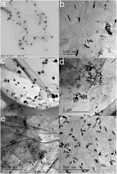
Fig. 2 shows the microscopy images of modified GO obtained under different magnifications. Fig. 2(a) shows the image of the modified GO. Black dots were scattered at the edge of GO. The active functional groups at the edge of GO were identified as the carboxyl and epoxy groups.24,25 The grafting reaction mainly occurred between the carboxyl group and TGIC. Therefore, the black dots were identified as TGIC. Fig. 2(b) to (d) show the different forms of the modified GO. During GO surface modification, the shape and size of the microstructure of the organic molecule can be influenced by the oxidation degree of the graphite, the ring-opened rate of the epoxy group in TGIC, the reactive site, and the rate of the grafting reaction. Therefore, the forms of TGIC are not the same. Three kinds of morphologies are presented in Fig. 2: a willow-leaf shape in Fig. 2(b), irregular polygons in Fig. 2(c), and spheres in Fig. 2(d). The coexistence of leaf-shaped and spherical organic molecules in Fig. 2(e) provides evidence that morphological changes had occurred. The aggregation of TGIC can be observed in Fig. 2(d). The degree of aggregation is dependent on the joining speed and order of the reactants. If GO is added to the ring-opened TGIC, the ring-opened TGIC may agglomerate. If reactants are added in reverse order, the ring-opened TGIC may disperse more uniformly and improve the grafting effect, as confirmed by the data shown in Fig. 2(f).3.2 FTIR
Fig. 3 shows the FTIR of spectra of TGIC, ring-opened TGIC, GO, and modified GO. Fig. 3(a) shows a magnified image of Fig. 3(b). TGIC is an ether with three epoxy groups. The characteristic peaks of the epoxy group in ether were present in the regions of 1280–1240 cm−1 (8 μpeak) and 840–750 cm−1 (12 μpeak). The band at 840 and 1251 cm−1 in the spectrum of TGIC in Fig. 3(a) was attributed to the stretching vibrations of the epoxy group. After the ring-opened reaction, the peak strength at the corresponding position of the black curve in Fig. 3(a) considerably weakened, demonstrating that the epoxy group in TGIC had opened. Another characteristic functional group in TGIC is carbonyl (C![[double bond, length as m-dash]](https://www.rsc.org/images/entities/char_e001.gif) O), which has a characteristic peak at 1750–1680 cm−1.26 The characteristic peak of carbonyl (C
O), which has a characteristic peak at 1750–1680 cm−1.26 The characteristic peak of carbonyl (C![[double bond, length as m-dash]](https://www.rsc.org/images/entities/char_e001.gif) O) was found at 1695 cm−1 in the spectrum shown in Fig. 3(b). The ring-opening reaction produced numerous hydroxyl groups. The broad peak at 3373 cm−1 shown in Fig. 3(b) can be attributed to the presence of hydroxyl groups. The opening of the epoxy group and the formation of hydroxyl in TGIC can be deduced from the above analysis. In Fig. 3(c), the peaks at 1311 and 1485, 1745, and 3166 cm−1 were attributed to the alcoholic hydroxyl group, carbonyl group, and hydroxyl group, respectively.27 After surface modification, new characteristic peaks formed at 1218, 1735, and 3375 cm−1 and were attributed to the C–N bond, carbonyl group, and hydroxyl group, respectively.28,29 The appearance of the above three characteristic peaks matched the reaction mechanism shown in Fig. 1 and fully demonstrated that the ring-opened TGIC was successfully grafted on GO.
O) was found at 1695 cm−1 in the spectrum shown in Fig. 3(b). The ring-opening reaction produced numerous hydroxyl groups. The broad peak at 3373 cm−1 shown in Fig. 3(b) can be attributed to the presence of hydroxyl groups. The opening of the epoxy group and the formation of hydroxyl in TGIC can be deduced from the above analysis. In Fig. 3(c), the peaks at 1311 and 1485, 1745, and 3166 cm−1 were attributed to the alcoholic hydroxyl group, carbonyl group, and hydroxyl group, respectively.27 After surface modification, new characteristic peaks formed at 1218, 1735, and 3375 cm−1 and were attributed to the C–N bond, carbonyl group, and hydroxyl group, respectively.28,29 The appearance of the above three characteristic peaks matched the reaction mechanism shown in Fig. 1 and fully demonstrated that the ring-opened TGIC was successfully grafted on GO.
3.3 SEM
The SEM images of novolac epoxy and the modified GO/novolac epoxy composite are shown in Fig. 4. The weight percentage of modified GO in the composites from Fig. 4(a) to (f) was 0, 5.5 wt%, 14.9 wt%, 22.6 wt%, 29 wt%, 34.4 wt% separately in Fig. 4(a), the cross-section morphology of novolac epoxy is considerably smoother than that of the modified GO/novolac epoxy composite. Black dots are visible in Fig. 4(b). Some of these black dots, which were identified as modified GO, remained isolated, whereas some were in contact with each other. As shown in Fig. 4(c) and (d), modified GO combined well with the matrix and distributed uniformly.30–32 Fig. 4(e) and (f) illustrate the formation of heat conduction pathways with the increasing weight percentage of modified GO in the composite. The formation of the heat conduction pathways33 can be deduced on the basis of the above analysis. The thermal property will increase with increasing filler content. However, the increase in filler content will also negatively affect the comprehensive performances, such as mechanical property, of the composite. Therefore, all results should be considered for the selection of the optimal proportion of modified GO.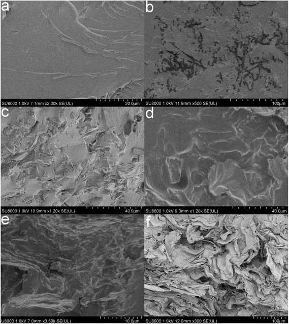 | ||
| Fig. 4 SEM images of pure novolac epoxy (a) and modified GO/novolac epoxy composite ((b) (5.5 wt%), (c) (14.9 wt%), (d) (22.6 wt%), (e) (29 wt%), and (f) (34.4 wt%)). | ||
3.4 TGA
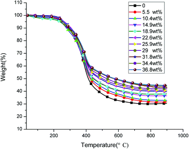
Fig. 5 shows the weight loss curves of the novolac epoxy and modified GO/novolac epoxy composite. This figure demonstrates that the decomposition trends of the 11 curves are all the same. Novolac epoxy exhibited the lowest residue weight when the increase in temperature was terminated. The residue weight increased gradually with the increasing weight percentage of modified GO in the composite. The corresponding TGA parameters are shown in Table 1. The 5% weight loss temperature for novolac epoxy was 251 °C. The 5% weight loss temperature of the modified GO/novolac epoxy composites were all higher than that of novolac epoxy when the weight percentage of modified GO in the composite reached 5.5%, 10.4%, and 14.9%. By contrast, the 5% weight loss temperature of the modified GO/novolac epoxy composites decreased when the weight percentage of modified GO in the composite reached 18.9%. This trend occurred because the thermal conductivity of the composite improved as the filler content increased. The heat transfer to internal novolac epoxy was accelerated, thus increasing the weight-loss ratio in the low-temperature region. In the meantime, the basic pathway of thermal conductivity was formed. The agglomeration and uneven dispersion of fillers in the matrix were inevitable. Therefore, the 5% weight loss temperature slightly fluctuated as the weight percentage of modified GO in the composite continuously increased. When the temperature increased to 200 °C, labile oxygen functional groups (hydroxyl, carboxyl, and carbonyl groups) and the unreacted novolac epoxy or other impurity traces began to decompose.34,35 The labile oxygen functional groups transformed into CO, CO2, and water vapor. As temperature further increased, the main decomposition process began and was attributed to the degradation of the cured novolac epoxy network.36,37 From 450 °C to 600 °C, the skeleton of the carbon atoms began to degrade. As shown in Table 1 and Fig. 7, the 50% weight loss temperature increased as the weight percentage of modified GO in the composite increased. The corresponding temperature of the maximum weight loss rate gradually increased from 380 °C to 400 °C. In addition, the curves became restrained from 400 °C to 600 °C, illustrating the termination of the primary decomposition process. Throughout the whole 11 curves, the residue weight obtained at above 400 °C was directly proportional to the weight percentage of modified GO in the composite. Similarly, under the same residue weight, the corresponding temperature was directly proportional to the weight percentage of modified GO in the composite. This phenomenon was caused by interfacial bonding and the improved interface between the modified GO/novolac epoxy composites. The barrier effect of the modified GO prevented the modified GO/novolac epoxy composite from decomposing.38 Based on the above analyses, the thermal stability of the composites has been enhanced.| Fillers content (wt%) | T5%a (°C) | T50%b (°C) | Tmaxc (°C) | R900d (%) |
|---|---|---|---|---|
| a Thermal degradation temperature of 5% weight loss.b Thermal degradation temperature of 50% weight loss.c Temperature of the maximum rate of degradation.d Residue weight at 900 °C. | ||||
| 0 | 251 | 414 | 388 | 30.03 |
| 5.5 | 273 | 429 | 393 | 32.75 |
| 10.4 | 259 | 431 | 391 | 32.82 |
| 14.9 | 253 | 437 | 397 | 34.20 |
| 18.9 | 237 | 443 | 393 | 37.81 |
| 22.6 | 260 | 486 | 394 | 39.66 |
| 25.9 | 262 | 530 | 395 | 42.67 |
| 29 | 246 | 535 | 396 | 42.98 |
| 31.8 | 255 | 551 | 395 | 43.10 |
| 34.4 | 246 | 564 | 397 | 44.01 |
| 36.8 | 259 | 580 | 396 | 44.67 |
3.5 DSC
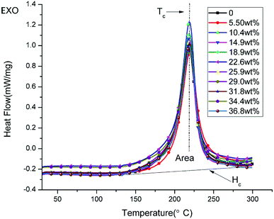
Fig. 6 shows the DSC curves of the uncured powders of novolac epoxy and uncured modified GO/novolac epoxy. The crystallization temperature Tc and the area of the exothermic peak Hc are shown in Table 2. The crystallization temperature Tc remained unchanged and only slightly fluctuated from 218 °C to 220 °C. When the composite contained 10.4 wt% modified GO, the released heat value Hc increased from 378.2 (J g−1) to 422 (J g−1), thus increasing by 43.8 (J g−1). This phenomenon illustrated that crystallization was facilitated by the modified GO. Then, the released heat decreased as the volume fraction increased but remained higher than that of pure resin.| Fillers content (wt%) | Tc (°C) | Hc (J g−1) |
|---|---|---|
| 0 | 218.0 | 378.2 |
| 5.5 | 219.7 | 390.8 |
| 10.4 | 219.0 | 422.0 |
| 14.9 | 218.3 | 386.3 |
| 18.9 | 218.7 | 392.0 |
| 22.6 | 218.8 | 399.5 |
| 25.9 | 218.6 | 391.5 |
| 29 | 219.1 | 392.0 |
| 31.8 | 219.0 | 392.9 |
| 34.4 | 218.9 | 384.3 |
| 36.8 | 219.3 | 381.8 |
3.6 DMA
Dynamic thermomechanical analysis is an analytical method that reflects the relationship between time, temperature, and the mechanical property of viscoelastic material. Fig. 7(a) shows the storage modulus of the novolac epoxy and the modified GO/novolac epoxy composite. The storage modulus reflects the resilience of a material after deformation.39 The results in Fig. 7(a) show that the glass transition of novolac epoxy terminated in the low-temperature zone, which ranged from approximately 75 °C to 140 °C. Then, the curve reached the minimum. This phenomenon likely resulted from the softening of the polymer chains. The corresponding temperature zone of the glass transition of the modified GO/novolac epoxy composite was 130 °C to 200 °C, which was almost 60 °C higher than that of novolac epoxy, when the weight percentage of modified GO in the composite reached 14.9%. This finding is mainly attributed to the internal crosslinking between the matrix and the filler.40 The degree of crosslinking will increase with increasing volume fraction, thus strengthening energy storage. The movement of the polymer chain segment will be hindered under external stress. Therefore, the stiffness of the modified GO/novolac epoxy composite will increase.41 When the weight percentage of modified GO in the composite increased to 22.6%, the value of the storage modulus of the modified GO/novolac epoxy composite increased by another order of magnitude. At this stage, the filler was extended throughout the whole matrix. Therefore, as inferred from the observation of the curves in the low-temperature region, the thermally conductive network efficiently prevented the movement of molecular chains. From approximately RT to 140 °C, a slight decrease resulted from secondary transition—β transition, γ transition, and δ transition—in the system. These transitions reflect the movement of the side chains and terminal groups in the polymer. As temperature increased from 140 °C to 200 °C, the curves sharply decreased because glass transition, which is the main transition (also referred to as α transition) in this system occurred. At this stage, the main chains in the polymer began to move and caused considerable mechanical loss. After glass transition, the modified GO/novolac epoxy composite transitioned into a high elastic state and the storage modulus remained stable. The final storage modulus of composites with high modified GO content was almost 200 MPa, which is significantly higher than that of novolac epoxy.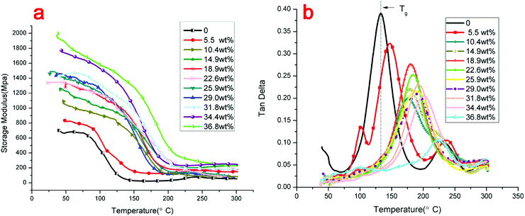 | ||
| Fig. 7 Dynamic mechanical properties of novolac epoxy and modified GO/novolac epoxy composites: (a) storage modulus, (b) loss factor. | ||
Fig. 7(b) shows the loss factor tan![[thin space (1/6-em)]](https://www.rsc.org/images/entities/char_2009.gif) δ. The loss factor tan
δ. The loss factor tan![[thin space (1/6-em)]](https://www.rsc.org/images/entities/char_2009.gif) δ is the ratio of the loss modulus and storage modulus. The largest peak represents glass transition. During glass transition, the movement of molecular chains caused great internal friction. The loss modulus reached the maximum value at a certain temperature, which is defined as the glass transition temperature (Tg). The glass transition temperature (Tg) of each data set is shown in Table 3. As shown in Fig. 7(b), the glass transition region of the modified GO/novolac epoxy composite shifted to a higher temperature zone compared with that of novolac epoxy. This trend was consistent with the storage modulus shown in Fig. 7(a). The Tg for novolac epoxy was 132 °C. When the weight percentage of modified GO in the composite reached 36.8%, the Tg of the modified GO/novolac epoxy composite was 222 °C. Specifically, heat resistance improved by almost 90 °C with the addition of modified GO. As the weight percentage of modified GO in the composite increased from 0% to 36.8%, the overall trend of peak height gradually decreased due to the increasing loss modulus and decreasing storage modulus. This behavior is a characteristic of cross-linked polymers. However, the peak height exhibited a slightly irregular change from 14.9 wt% to 29 wt% as a likely effect of the inevitable non-uniform distribution and localized clustering of fillers.42,43 Then, the state of crosslinking could affect the loss modulus and storage modulus of the composite. Furthermore, the surface roughness of modified GO with corrugated morphology could also affect crosslinking. The wrinkled structure and large specific surface area of modified GO facilitated strong interfacial interactions with the matrix, even influencing the curing reaction rate.44,45 Then, the degree of crosslinking could be influenced. Finally, the tan
δ is the ratio of the loss modulus and storage modulus. The largest peak represents glass transition. During glass transition, the movement of molecular chains caused great internal friction. The loss modulus reached the maximum value at a certain temperature, which is defined as the glass transition temperature (Tg). The glass transition temperature (Tg) of each data set is shown in Table 3. As shown in Fig. 7(b), the glass transition region of the modified GO/novolac epoxy composite shifted to a higher temperature zone compared with that of novolac epoxy. This trend was consistent with the storage modulus shown in Fig. 7(a). The Tg for novolac epoxy was 132 °C. When the weight percentage of modified GO in the composite reached 36.8%, the Tg of the modified GO/novolac epoxy composite was 222 °C. Specifically, heat resistance improved by almost 90 °C with the addition of modified GO. As the weight percentage of modified GO in the composite increased from 0% to 36.8%, the overall trend of peak height gradually decreased due to the increasing loss modulus and decreasing storage modulus. This behavior is a characteristic of cross-linked polymers. However, the peak height exhibited a slightly irregular change from 14.9 wt% to 29 wt% as a likely effect of the inevitable non-uniform distribution and localized clustering of fillers.42,43 Then, the state of crosslinking could affect the loss modulus and storage modulus of the composite. Furthermore, the surface roughness of modified GO with corrugated morphology could also affect crosslinking. The wrinkled structure and large specific surface area of modified GO facilitated strong interfacial interactions with the matrix, even influencing the curing reaction rate.44,45 Then, the degree of crosslinking could be influenced. Finally, the tan![[thin space (1/6-em)]](https://www.rsc.org/images/entities/char_2009.gif) δ varied in a small range. The above analysis revealed that the addition of modified GO enhanced interfacial interaction between the filler and the matrix. The formed covalent bonds restricted the movement of the polymer chains.46,47 The shifting of Tg confirmed that the crosslinking density of the thermal conductivity composite increased.48 Therefore, the addition of modified GO improves the thermal stability and mechanical properties of the modified GO/novolac epoxy composite.
δ varied in a small range. The above analysis revealed that the addition of modified GO enhanced interfacial interaction between the filler and the matrix. The formed covalent bonds restricted the movement of the polymer chains.46,47 The shifting of Tg confirmed that the crosslinking density of the thermal conductivity composite increased.48 Therefore, the addition of modified GO improves the thermal stability and mechanical properties of the modified GO/novolac epoxy composite.
| Fillers content (wt%) | Tg (°C) |
|---|---|
| 0 | 132 |
| 5.5 | 147 |
| 10.4 | 176 |
| 14.9 | 178 |
| 18.9 | 180 |
| 22.6 | 185 |
| 25.9 | 189 |
| 29 | 190 |
| 31.8 | 192 |
| 34.4 | 202 |
| 36.8 | 222 |
3.7 The interface between thermal conductive filler and novolac epoxy matrix
After the experiment of DMA, the surface morphology of sections was examined by SEM. Fig. 8(a) and (b) show the sections of composite filled with GO. It is shown that the pores and gaps between GO sheets and the matrix are clearly visible (Fig. 8(a)). The dispersion of GO in the matrix is not uniform enough. There is also a cluster of GO can be seen in Fig. 8(b). It is obvious that the interface between GO and the matrix is so bad that the GO and the matrix cannot combine tightly. Therefore, it is hard to make the heat transfer effective because of the air which has the lowest thermal conductivity. In contrast, on the fracture surface of the composite containing modified GO, it is shown that the modified GO dispersed uniformly in the matrix and forms tortuous river-like structures, which can be inferred that the combination between filler and matrix has been improved. The tortuous river-like structures would restrict the micro-crack propagation in the composites.49 The considerable fracture energy is likely to be dissipated as the formation of the tortuous river-like structures. With the functionalization improves the dispersion of GO and interfacial interaction between the filler and the matrix, the critical stress necessary to cause the sheet/sheet or sheet/matrix interfacial failure increases, thus lead to much more fracture energy dissipation.50,51 Above all, functionalization of GO do improves both the dispersion and interface in the modified GO/novolac epoxy composite.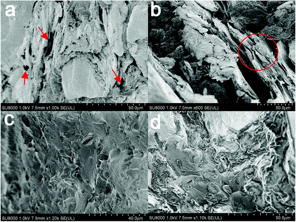 | ||
| Fig. 8 SEM images of fracture surface of composite samples with 18.9 wt% (40 vol%) GO (a and b); 18.9 wt% (40 vol%) modified GO (c and d). | ||
3.8 Thermal conductivity
Fig. 9 shows the experimental results for the modified GO/novolac epoxy composite and thermal conductivity models, including the Maxwell–Eucken,52 Nielsen–Lewis,53 Russell,54 and Agari55 models.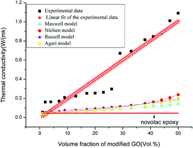 | ||
| Fig. 9 Thermal conductivity curves of experimental data, thermal conductivity models, and prediction model. | ||
For the Maxwell–Eucken model:
| λc = λ1[(λ2 + 2λ1 + 2V2(λ2 − λ1))/(λ2 + 2λ1 − V2(λ2 − λ1)) | (1) |
For the Nielsen–Lewis model:
 | (2) |
λc is thermal conductivity, λ1 is the thermal conductivity of matrix, λ2 is the thermal conductivity of filler, V is volume fraction.
Vm is the maximum accumulation volume fraction of the dispersed filler, in general case, the values of Vm and A are set as 0.64 and 3.
For the Russell model:
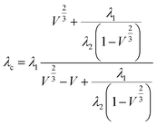 | (3) |
For the Agari model:
log![[thin space (1/6-em)]](https://www.rsc.org/images/entities/char_2009.gif) λc = (1 − V)log λc = (1 − V)log![[thin space (1/6-em)]](https://www.rsc.org/images/entities/char_2009.gif) (C1λ1) + VC2 (C1λ1) + VC2![[thin space (1/6-em)]](https://www.rsc.org/images/entities/char_2009.gif) log log![[thin space (1/6-em)]](https://www.rsc.org/images/entities/char_2009.gif) λ2 λ2
| (4) |
Fig. 9 shows the comparison of the values of the thermal conductivity models with the experimental data of the modified GO/novolac epoxy composite. In solid materials heat is carried by acoustic phonons.56 Heat conduction in carbon materials is usually dominated by phonons even for graphite.57 Under the volume fraction of 9%, the filler was encapsulated and remained isolated in the matrix, whereas the matrix was continuous. Therefore, the fillers could not touch each another at a low volume fraction.58 At this stage the thermal conductivity of the composite increased slightly. At the stage of 9 vol% to 26 vol%, the thermal conductivity increased slowly but steadily. The filler allowed the conduction of phonons over short distance as the volume fraction of filler is not high enough.59 At the same time a locally thermal conductive network was formed as fillers started to come in contact with each other. With the further addition of modified GO, an inter-connected thermal conductive network was formed over the whole matrix, which was consist of locally thermal conductive network. When the volume fraction of modified GO in the composite varied from 26% to 29%, the thermal conductivity of the modified GO/novolac epoxy composite was 0.671 W m−1 K−1, which was almost 2.3 times that of 26 vol%’s. Therefore, 26 vol% is the percolation threshold in this heat conduction system.60 At the last stage, the thermal conductive network was gradually formed in the entirety of the resin matrix. That's because the fillers scattered in the matrix densely. So they came into contact with each other and transmit heat to the composite, under the help of phonons. The thermal conductivity of the composite increased rapidly from 0.671 W m−1 K−1 to 1.091 W m−1 K−1 with the incorporation of 29 vol% to 50 vol% modified GO. At the last stage of volume increase, the thermal conductivity continued to increase at a slower rate, illustrating that the increase in volume fraction is one of the factors that affect thermal conductivity at this stage. The decrease in interfacial adhesion between the matrix and the fillers, dispersion of fillers, interfacial thermal resistance between the fillers and matrix and the bubbles produced in the hot pressing process will also affect the final thermal conductivity of the modified GO/novolac epoxy composite by various degrees.
Observing the predictive model curves revealed that the four models exhibited the same trend with experimental data before the addition of 29 vol% modified GO in the composite. In this stage, the curves exhibited gradual linear growth. The growth trend then deviated from the experimental data because of various reasons: The Maxwell–Eucken model assumes that the particle is spherical in shape and ignores the high volume fraction and the gap of thermal conductivity between the matrix and filler. In this study, the thermal conductivity of the novolac epoxy was only 0.044 W m−1 K−1. The considerable gap between the filler and matrix should not be neglected. The Nielsen model is appropriate for heat conduction systems with low levels of filler, and the constants A and B are summarized from previous data. Based on the consistent growth trend between the Nielsen model and experimental data, we can infer that if the proper constants A and B are found, the Nielsen model could fit the experimental data well for the composites that contain low volume fractions of modified GO. The Russell model assumes that the dispersed phase is also scattered in the matrix with the same size and remains in isolation, which violates the theory of the thermal conductive network analyzed above. The deviation in the Agari model may be caused by constants C1 and C2, which may vary in different systems.61 The characterization of constants C1 and C2 requires detailed investigation.
A simple and practical characteristic model is obtained by fitting the experimental data. The equation of the model is as follows:
| λc = 0.011V + 0.077 | (5) |
The above analysis shows that the growth process of thermal conductivity can be divided into three stages. In the first stage, the thermal conductivity increased slowly but steadily. The filler remained almost isolated. In the second stage, the thermal conductive network was gradually formed over the entirety of the resin matrix. In the third stage, the thermal conductivity continued to increase at a slow rate. When the volume fraction reached 50%, the thermal conductivity remained at 1.091 W m−1 K−1, which is 24.8-fold that of novolac epoxy. The increase in thermal conductivity of the composite with increasing concentration of modified GO could be attributed to the following factors: the inter-connected thermal conductive propagation in modified GO mainly resulted from acoustic phonons.62 After being modified, in comparison with the pure GO, functionalization of the GO sheets leads in the improvement of the phonon coupling of functionalized GO and novolac epoxy.63 A similar phenomenon was also observed in Gu's work.64 The noticeable improvement of thermal conductivity showed that the modified GO has an important role in inhibiting aggregation and facilitating dispersion in the matrix.65 The uniform dispersion and thermal conductive pathways of the matrix contributed to the increase in thermal conductivity. Therefore, the incorporation of modified GO in novolac epoxy improves the thermal conductivity of the modified GO/novolac epoxy composite.
4. Conclusion
A facile GO functionalization method was reported in this paper. Samples of modified GO/novolac epoxy composite were prepared with different volume fractions of modified GO. The results from FTIR, SEM, and TEM confirmed that the ring-opened TGIC was successfully grafted on GO. The filler dispersed in the matrix well due to good interfacial interaction. The addition of modified GO improved the energy storage capacity of the modified GO/novolac epoxy composite because of molecular crosslinking between the filler and matrix. The DMA data demonstrated that when the weight percentage of modified GO in novolac epoxy reached 36.8% the modified GO/novolac epoxy composite had a Tg value of 222 °C, which was 90 °C higher than that of novolac epoxy. Moreover, TGA analysis was performed to illustrate the decomposition mechanism of the modified GO/novolac epoxy composite. The TGA data showed that the temperature of the maximum degradation rate improved by 12 °C. The thermal conductivity of the modified GO/novolac epoxy composite reached 1.091 W m−1 K−1, which was 25 times higher than that of novolac epoxy, when the composite was modified with 50 vol% modified GO. The above results illustrated that the addition of modified GO to novolac epoxy improved various properties and can possibly be applied to other similar thermal interface materials.Conflicts of interest
There are no conflicts to declare.Acknowledgements
This work was supported by the National Natural Science Foundation of China (No. 51772243), the Provincial Natural Science Foundation Research Project of Shaanxi (No. 2017JQ5039), the innovative talent promotion program of Shaanxi (2017KTC-17), the Science and Technology Planning Project of Xi'an (CXY1509(11)) and the Scientific and Technological Innovation Project of Xi'an University of Technology (No. 2014CX007).References
- Y. X. Fu, Z. X. He, D. C. Mo and S. S. Lu, Thermal conductivity enhancement with different fillers for epoxy resin adhesives, Appl. Therm. Eng., 2014, 66, 493–498 CrossRef.
- L. C. Sim, S. R. Ramanan, H. Ismail, K. N. Seetharamu and T. J. Goh, Thermal characterization of Al2O3 and ZnO reinforced silicone rubber as thermal pads for heat dissipation purposes, Thermochim. Acta, 2005, 430, 155–165 CrossRef.
- M. Hao, Z. Huang, K. R. Saviers, G. Xiong, S. L. Hodson and T. S. Fisher, Characterization of vertically oriented carbon nanotube arrays as high-temperature thermal interface materials, Int. J. Heat Mass Transfer, 2017, 106, 1287–1293 CrossRef.
- Y. Sun, B. Tang, W. Huang, S. Wang, Z. Wang, X. Wang, Y. Zhu and C. Tao, Preparation of graphene modified epoxy resin with high thermal conductivity by optimizing the morphology of filler, Appl. Therm. Eng., 2016, 103, 892–900 CrossRef.
- I. Burmistrov, N. Gorshkov, I. Ilinykh, D. Muratov, E. Kolesnikov, S. Anshin, I. Mazov, J.-P. Issi and D. Kusnezov, Improvement of carbon black based polymer composite electrical conductivity with additions of MWCNT, Compos. Sci. Technol., 2016, 129, 79–85 CrossRef.
- A. A. Balandin, S. Ghosh, W. Bao, I. Calizo, D. Teweldebrhan, F. Miao and C. Lau, Superior Thermal Conductivity of Single-Layer Graphene, Nano Lett., 2008, 8, 902–907 CrossRef PubMed.
- X. Wang, Y. Zhao, J. Jin and M. Song, A comparative study on the effect of carbon fillers on electrical and thermal conductivity of a cyanate ester resin, Polym. Test., 2017, 60, 293–298 CrossRef.
- L. Yi, G. Hu and H. Li, Against overcharring design of flame-retardant electromagnetic absorbing composites with graphene nanosheets and manganese oxides in modified epoxy resin, Ind. Eng. Chem. Res., 2016, 55, 934–947 CrossRef.
- G. Huang, S. Chen, S. Tang and J. Gao, A novel intumescent flame retardant-functionalized graphene: nanocomposite synthesis, characterization, and flammability properties, Mater. Chem. Phys., 2012, 135, 938–947 CrossRef.
- S. Fathalipour and M. Mardi, Synthesis of silane ligand-modified graphene oxide and antibacterial activity of modified graphene-silver nanocomposite, Mater. Sci. Eng., C, 2017, 79, 55–65 CrossRef PubMed.
- C. Nethravathi and M. Rajamathi, Delamination, colloidal dispersion and reassembly of alkylamine intercalated graphite oxide in alcohols, Carbon, 2006, 44, 2635–2641 CrossRef.
- R. Dong and L. Liu, Preparation and properties of acrylic resin coating modified by functional graphene oxide, Appl. Surf. Sci., 2016, 368, 378–387 CrossRef.
- Y. Xu, Q. Gao, H. Liang and K. Zheng, Effects of functional graphene oxide on the properties of phenyl silicone rubber composites, Polym. Test., 2016, 54, 168–175 CrossRef.
- T. T. Nguyen, P. Bandy opadhyay, X. Li, N. H. Kim and J. H. Lee, Effects of grafting methods for functionalization of graphene oxide by dodecylamine on the physical properties of its polyurethane nanocomposites, J. Membr. Sci., 2017, 540, 108–119 CrossRef.
- Y. J. Wan, L. C. Tang, L. X. Gong, D. Yan, Y. B. Li, L. B. Wu, J. X. Jiang and G. Q. Lai, Grafting of epoxy chains onto graphene oxide for epoxy composites with improved mechanical and thermal properties, Carbon, 2014, 69, 467–480 CrossRef.
- Y. Lin, J. Jin and M. Song, Preparation and characterisation of covalent polymer functionalized grapheme oxide, Mater. Chem., 2011, 21, 3455–3461 RSC.
- S. Xia, Y. Liu and F. Pei, Identical steady tribological performance of graphene-oxide-strengthened polyurethane/epoxy interpenetrating polymer networks derived from graphene nanosheet, Polymer, 2015, 64, 62–68 CrossRef.
- J. P. Agrawal, N. M. Bhide and S. R. Naidu, Study on curing of novolac epoxy resin, J. Therm. Anal., 1993, 39, 351–358 CrossRef.
- T. Kavinkumar and S. Manivannan, Thermal and dielectric properties of multi-walled carbon nanotube–graphene oxide composite, J. Mater. Sci.: Mater. Electron., 2017, 28, 344–353 CrossRef.
- H. Beyer, I. Sajó, Á. Szegedi and V. Vargha, Morphology and crystallinity of the two diastereomer racemates of triglycidyl isocyanurate (TGIC), Eur. Polym. J., 2007, 43, 2350–2356 CrossRef.
- R. V. D. Linde, E. G. Belder and Y. P. Dan, Effect of physical aging and thermal stress on the behavior of polyester/TGIC powder coatings, Prog. Org. Coat., 2000, 40, 215–224 CrossRef.
- W. Yang, B. Li, M. Lu and G. Xu, Synthesis and Characterization of Waterborne Polyurethane Modified with Epoxy Resin which was Ring-Opened by Lactic Acid, Paint Coat. Ind., 2011, 41, 22–24 Search PubMed.
- G. Sabitha, R. S. Babu, M. Rajkumar, C. S. Reddy and J. S. Yadav, Highly regioselective ring opening of epoxides and aziridines using cerium(III) chloride, Tetrahedron Lett., 2001, 42, 3955–3958 CrossRef.
- R. Moosaei, M. Sharif and A. Ramezannezhad, Enhancement of tensile, electrical and thermal properties of epoxy nanocomposites through chemical hybridization of polypyrrole and graphene oxide, Polym. Test., 2017, 60, 173–186 CrossRef.
- G. Goncalves, P. A. A. P. Marques, A. Barros-Timmons, I. Bdkin, M. K. Singh, N. Emami and J. Grácio, Graphene oxide modified with PMMA via ATRP as a reinforcement filler, Mater. Chem., 2010, 20, 9927–9934 RSC.
- F. Sun, T. Yu, C. Hu and Y. Li, Influence of functionalized graphene by grafted phosphorus containing flame retardant on the flammability of carbon fiber/epoxy resin (CF/ER) composite, Compos. Sci. Technol., 2016, 136, 76–84 CrossRef.
- S. Zhu, Y. Cen, M. Yang, J. Guo, C. Chen, J. Wang and W. Fan, Probing the intrinsic active sites of modified graphene oxide for aerobic benzylic alcohol oxidation, Appl. Catal., B, 2017, 211, 89–97 CrossRef.
- S. Fathalipour and M. Mardi, Synthesis of silane ligand-modified graphene oxide and antibacterial activity of modified graphene-silver nanocomposite, Mater. Sci. Eng., C, 2017, 79, 55–65 CrossRef PubMed.
- W. Han, G. Zhao, X. Zhang, S. Zhou, P. Wang, Y. An and B. Xu, Graphene oxide grafted carbon fiber reinforced siliconborocarbonitride ceramics with enhanced thermal stability, Carbon, 2015, 95, 157–165 CrossRef.
- H. Guo, X. Li, B. Li, J. Wang and S. Wang, Thermal conductivity of graphene/poly(vinylidene fluoride) nanocomposite membrane, Mater. Des., 2017, 114, 355–363 CrossRef.
- K. Kim, G. Lee, Y. Yoo and J. Kim, Recycling of metal sludge wastes for thermal conductive filler via sintering and surface modification, J. Alloys Compd., 2017, 694, 1011–1018 CrossRef.
- W. H. Shin, K. Ahn, M. Jeong, J. S. Yoon, J. M. Song, S. Lee, W. S. Seo and Y. S. Lim, Enhanced thermoelectric performance of reduced grapheme oxide incorporated bismuth-antimony-telluride by lattice thermal conductivity reduction, J. Alloys Compd., 2017, 718, 342–348 CrossRef.
- X. Xiong, J. Wang, H. Jia, E. Fang and L. Ding, Structure, thermal conductivity, and thermal stability of bromobutyl rubber nanocomposites with ionic liquid modified graphene oxide, Polym. Degrad. Stab., 2013, 98, 2208–2214 CrossRef.
- Z. S. Pour and M. Ghaemy, Polymer grafted graphene oxide: For improved dispersion in epoxy resin and enhancement of mechanical properties of nanocomposite, Compos. Sci. Technol., 2016, 136, 145–157 CrossRef.
- S. J. Park and F. L. Jin, Thermal stabilities and dynamic mechanical properties of sulfone-containing epoxy resin cured with anhydride, Polym. Degrad. Stab., 2004, 86, 515–520 CrossRef.
- N. Grassie, M. I. Guy and N. H. Tennent, Degradation of epoxy polymers: Part 4-thermal degradation of bisphenol-A diglycidyl ether cured with ethylene diamine, Polym. Degrad. Stab., 1986, 14, 125–137 CrossRef.
- F. L. Jin and S. J. Parkb, Thermal properties of epoxy resin/filler hybrid composites, Polym. Degrad. Stab., 2012, 97, 2148–2153 CrossRef.
- W. S. Wang, H. S. Chen, Y. W. Wu, T. Y. Tsai and Y. W. Chen-Yang, Properties of novel epoxy/clay nanocomposites prepared with a reactive phosphorus-containing organoclay, Polymer, 2008, 49, 4826–4836 CrossRef.
- H. Yao, S. A. Hawkins and H. J. Sue, Preparation of epoxy nanocomposites containing well-dispersed graphene nanosheets, Compos. Sci. Technol., 2017, 146, 161–168 CrossRef.
- Q. Tian, Y. C. Yuan, M. Z. Rong and M. Q. Zhang, A thermally remendable epoxy resin, Mater. Chem., 2009, 19, 1289–1296 RSC.
- L. C. Tang, Y. J. Wan, D. Yan, Y. B. Pei, L. Zhao, Y. B. Li, L. B. Wu, J. X. Jiang and G. Q. Lai, The effect of graphene dispersion on the mechanical properties of graphene/epoxy composites, Carbon, 2013, 60, 16–27 CrossRef.
- L. C. Tang, H. Zhang, J. H. Han, X. P. Wu and Z. Zhang, Fracture mechanisms of epoxy filled with ozone functionalized multiwall carbon nanotubes, Compos. Sci. Technol., 2012, 72, 7–13 CrossRef.
- J. Shen, W. Huang, L. Wu, Y. Hu and M. Ye, The reinforcement role of different amino-functionalized multi-walled carbon nanotubes in epoxy nanocomposites, Compos. Sci. Technol., 2007, 67, 3041–3050 CrossRef.
- M. Fang, K. Wang, H. Lu, Y. Yang and S. Nutt, Covalent polymer functionalization of graphene nanosheets and mechanical properties of composites, J. Mater. Chem., 2009, 38, 7098–7105 RSC.
- J. Wu and D. D. L. Chung, Calorimetric study of the effect of carbon fillers on the curing of epoxy, Carbon, 2004, 42, 3039–3042 CrossRef.
- H. Im and J. Kim, Thermal conductivity of a graphene oxide–carbon nanotube hybrid/epoxy composite, Carbon, 2012, 50, 5429–5440 CrossRef.
- J. Zhou, Z. Yao, Y. Chen, D. Wei, Y. Wu and T. Xu, Mechanical and thermal properties of graphene oxide/phenolic resin composite, Polym. Compos., 2013, 34, 1245–1249 CrossRef.
- M. Ogata, N. Kinjo and T. Kawata, Effects of crosslinking on physical properties of phenol-formaldehyde novolac cured epoxy resins, J. Appl. Polym. Sci., 2010, 48, 583–601 CrossRef.
- L. Z. Guan, et al., Toward effective and tunable interphases in graphene oxide/epoxy composites by grafting different chain lengths of polyetheramine onto graphene oxide, J. Mater. Chem. A, 2014, 2.36, 15058–15069 Search PubMed.
- N. J. Huang, J. Zang and G. D. Zhang, et al., Efficient interfacial interaction for improving mechanical properties of polydimethylsiloxane nanocomposites filled with low content of graphene oxide nanoribbons, RSC Adv., 2017, 7.36, 22045–22053 RSC.
- Y. J. Wan, L. X. Gong and L. C. Tang, et al., “Mechanical properties of epoxy composites filled with silane-functionalized graphene oxide”, Composites, Part A, 2014, 64, 79–89 CrossRef.
- A. Eucken, Die Warmeleitfa higkeit keramischer feuerfester Stoffe, VDI-Forchungscheft, 1932, 353, 1–16 Search PubMed.
- L. E. Nielsen, Thermal conductivity of particulate-filled polymers, J. Appl. Polym. Sci., 2010, 17(12), 3819–3820 CrossRef.
- H. W. Russell, Principles of heat flow in porous insulators, J. Am. Ceram. Soc., 1935, 18(1–12), 1–5 CrossRef.
- Y. Agari and T. Uno, Estimation on Thermal Conductivities of Filled Polymers, J. Appl. Polym. Sci., 2010, 32, 5705–5712 CrossRef.
- A. A. Balandin, Thermal properties of graphene, carbon nanotubes and nanostructured carbon materials, Nat. Mater., 2011, 10, 569–581 CrossRef PubMed.
- P. G. Klemens, Theory of the A-Plane thermal conductivity of graphite, J. Wide Bandgap Mater., 2000, 7, 332–339 CrossRef.
- W. Zhou, J. Zuo and W. Ren, Thermal conductivity and dielectric properties of Al/PVDF composites, Composites, Part A, 2012, 43, 658–664 CrossRef.
- X. Wang, Y. Zhao, J. Jin and M. Song, A comparative study on the effect of carbon fillers on electrical and thermal conductivity of a cyanate ester resin, Polym. Test., 2017, 60, 293–298 CrossRef.
- S. Li, X. Shi, C. Fang and N. Liu, Effect of graphite and Ag-plated graphite nanoplatelets on the thermal properties of polypropylene nanocomposites: Experimental studies and modeling, Thermochim. Acta, 2016, 630, 11–20 CrossRef.
- H. He, R. Fu, Y. Han, Y. Shen and X. Song, Thermal conductivity of ceramic particle filled polymer composites and theoretical predictions, J. Mater. Sci., 2007, 42, 6749–6754 CrossRef.
- S. Chatterjee, J. W. Wang, W. S. Kuo, N. H. Tai, C. Salzmann, W. L. Li, R. Hollertz, F. A. Nüesch and B. T. T. Chu, Mechanical reinforcement and thermal conductivity in expanded graphene nanoplatelets reinforced epoxy composites, Chem. Phys. Lett., 2012, 531, 6–10 CrossRef.
- Z. Zabihi and H. Araghi, Effect of functional groups on thermal conductivity of graphene/paraffin nanocomposite, Phys. Lett. A, 2016, 380, 3828–3831 CrossRef.
- J. Gu, X. Yang, Z. Lv, N. Li, C. Liang and Q. Zhang, Functionalized graphite nanoplatelets/epoxy resin nanocomposites with high thermal conductivity, Int. J. Heat Mass Transfer, 2016, 92, 15–22 CrossRef.
- H. Ribeiro, W. M. D. Silva, J. C. Neves, H. D. R. Calado, R. Paniago, L. M. Seara, D. D. M. Camarano and G. G. Silva, Multifunctional nanocomposites based on tetraethylenepentamine-modified graphene oxide/epoxy, Polym. Test., 2015, 43, 182–192 CrossRef.
| This journal is © The Royal Society of Chemistry 2018 |

