 Open Access Article
Degradation of diuron by heterogeneous electro-Fenton using modified magnetic activated carbon as the catalyst†
Xi Wanga,
Kai Zhua,
Xiaoyue Maa,
Zhirong Sun *a and
Xiang Hu*b
aNational Engineering Laboratory for Advanced Municipal Wastewater Treatment and Reuse Technology, College of Environmental and Energy Engineering, Beijing University of Technology, Beijing 100124, China. E-mail: zrsun@bjut.edu.cn; Tel: +86-13718215082
bCollege of Chemical Engineering, Beijing University of Chemical Technology, Beijing 100029, China. E-mail: huxiang99@163.com
First published on 30th May 2018
Abstract
In this work, polytetrafluoroethylene coating was firstly conducted to make stable and effective magnetic-activated carbon as a heterogeneous electro-Fenton catalyst for diuron oxidation. The catalysts were characterized by scanning electron microscopy (SEM), X-ray photoelectron spectroscopy (XPS) and X-ray diffraction (XRD). In addition, the effects of operating parameters such as catalyst dosage, current intensity, substrate concentration and pH on the degradation of diuron were investigated. The removal efficiency of diuron was more than 95% within 120 min oxidation under the conditions of I = 100 mA, pH = 6.7 ± 0.2, catalyst loading 3 g L−1 and diuron concentration 10 mg L−1. Moreover, the catalyst durability test demonstrated that the modification of 5% PTFE on the catalyst indeed has a significant beneficial effect on the useful life of the catalyst. We compared the performance of catalysts with or without PTFE modification in consecutive experiments; the modified catalysts exhibited remarkable advantages in that the diuron removal efficiency was stable with relatively low iron leaching (<0.1 mg L−1) during ten consecutive degradation experiments, which proved the durability and reusability of the modified catalyst. This work demonstrates that such a heterogeneous EF using stable magnetic activated carbon catalyst with PTFE modification is promising for organic wastewater treatment in initial neutral pH conditions; at the same time, these good properties of the modified catalyst increase the possibility of practical application.
1. Introduction
Pesticides are widely used in agricultural production all over the world. Their remnants may have adverse effects on the ecological balance in the environment and be a potential threat to the survival of many living organisms and plants. Diuron [3-(3,4-dichlorophenyl)-1,1-dimethylurea], one of the most commonly used herbicides, is widely used for weed elimination in pre- and post-emergence to remove annual broadleaf weeds and perennial broadleaf weeds.1,2 Diuron has good chemical stability and its half-life in nature is over 370 days. Despite its low solubility in water, diuron can still slowly dissolve in water and penetrate the soil, causing pollution of the groundwater and surface water.3 Hence, it is regarded as a priority hazardous substance by the European Commission and the Occupational Safety and Health Administration in the United States (OSHA Hazard Communication Standard 29 CFR 1910.1200).4 In addition, diuron is a suspected carcinogenic and genotoxic compound,5 and owing to the toxicity of diuron, diuron-containing wastewater is difficult to handle in conventional biofilm-based wastewater treatment plants.4Nowadays, plenty of methods are investigated for the treatment of persistent organic pollutants in effluent, such as photocatalysis,6 electrochemistry,7 Fenton's reaction8 and adsorption.9 Among these methods, advanced oxidation processes (AOPs) attract researchers' attention because of the clean and efficient features. In addition, AOPs have been further developed through the combination of light (ultraviolet light, sunlight) or electrochemical systems to obtain higher efficiency. Indeed, various electrochemical advanced oxidation processes (EAOPs) have been developed for effective degradation of persistent organic pollutants (POPs).10 EAOPs with powerful oxidation ability are applied to remove harmful persistent pollutants, such as organic synthetic dyes, pharmaceuticals and personal care products (PPCPs), in the aquatic environment.11 Electro-Fenton process (EF) based on the Fenton reaction developed rapidly over the past decade. In contrast to the Fenton reaction, which requires additional hydrogen peroxide, hydrogen peroxide during the EF progress is electrogenerated in situ at a suitable cathode fed with oxygen or air, as described in eqn (1).11 The hydrogen peroxide reacts with the iron in the catalyst to generate a highly oxidizing hydroxyl radical (˙OH) (eqn (2)), which could lead to non-selective oxidation of organic pollutants in wastewater.12–14
| O2 + H+ + 2e → H2O2 | (1) |
| H2O2 + Fe2+ → Fe3+ + ˙OH + OH− | (2) |
Compared with the traditional homogeneous electro-Fenton reaction, the heterogeneous electro-Fenton reaction has several advantages, such as a broader pH range and lesser generation of iron sludge.15–18 In the heterogeneous electro-Fenton reaction, there are two different loading methods for catalysts. One is to load catalysts on the electrode materials. Many scholars have used this method to prepare highly efficient composite cathodes.19,20 Another is to load catalysts on the separated solid particles. The various materials used as efficient supports for iron and iron oxides are mostly porous in nature, such as clay,21,22 activated carbon,23,24 alumina, silica,25,26 and zeolite.27–29 Recent research has shown that magnetite is the most effective catalyst during the heterogeneous Fenton process in contrast to other iron oxides. This may be because the Fe2+ in the structure of the magnetite enhances the generation of hydroxyl radicals.30,31
Activated carbon, a kind of porous material that can be used as a catalyst carrier, exhibits many good characteristics, such as good stability, conductivity and high specific surface. In order to incorporate magnetic crystals into activated carbon, impregnation and calcination have been developed in many studies. However, there is still a problem that the activity of the catalyst may decrease when iron element forms complexes with carboxylic acid generated during the oxidation process.32 Herein, in this experiment, PTFE was used to modify the catalyst to delay inactivation and prolong the service life of the catalyst. We explored the activity and stability of the catalyst modified with PTFE under near-neutral conditions using diuron as the target pollutant in electro-Fenton, and 10 times degradation experiments were carried out continuously under the same conditions. It has proven that the catalyst with PTFE modification exhibits good stability and reusability during the electro-Fenton process under near-neutral conditions, which makes sense for industrial applications.
2. Materials and methods
2.1 Chemicals and materials
Diuron (3-(3,4-dichlorophenyl)-1,1-dimethylurea >98%), which was chosen as the model organic pollutant for the electro-Fenton oxidation, was supplied by TCI and used without any further purification. Commercial coconut shell-based activated carbon was supplied by Jumeijing, China, and Fe(NO3)3·9H2O used in the experiment was obtained from Sinopharm Chemical Reagent Beijing Co., Ltd. The graphite felt used as a cathode was purchased from Jiuhua Carbon. The anhydrous sodium sulfate (Na2SO4), sulfuric acid (H2SO4) and sodium hydroxide (NaOH) used in the experiments were analytical grade and were used without further purification. Methanol purchased from Tianjin Shield Company was used for the preparation of HPLC eluents. All the solutions were prepared with deionized Milli-Q water. Then, the activated carbon was filtered and dried completely at room temperature.2.2 Preparation of modified activated carbon catalyst
First, the activated carbon (3–5 mm) was washed repeatedly with ultrapure water to remove surface dust. Next, in order to remove the organic matter on the activated carbon, the activated carbon was washed into a certain amount of acetone (solid–liquid ratio of 1![[thin space (1/6-em)]](https://www.rsc.org/images/entities/char_2009.gif) :
:![[thin space (1/6-em)]](https://www.rsc.org/images/entities/char_2009.gif) 5) and sonicated for 15 min. Then the activated carbon was washed several times with ultrapure water to ensure that there was no residual acetone. After thoroughly cleaning the activated carbon, it was dried in a blast drying oven at 60 °C.
5) and sonicated for 15 min. Then the activated carbon was washed several times with ultrapure water to ensure that there was no residual acetone. After thoroughly cleaning the activated carbon, it was dried in a blast drying oven at 60 °C.
After pretreatment, the activated carbon (15 g) was immersed in a mixed solution (100 mL) of nitric acid (10% wt) and ferric nitrate (0.1 mol L−1) for 12 h. Then, the activated carbon was separated from the impregnated solution and dried at room temperature. The dried activated carbon was calcined at 600 °C for the formation of magnetite for 0.5 h under the protection of nitrogen. The calcinations process started from room temperature at a heating rate of 5 °C min−1.
Finally, the activated carbon was impregnated into different concentrations of PTFE solution (5% wt, 10% wt, 15% wt and 20% wt). After 1 h dipping, the activated carbon was separated from the solution by filtration and dried in a vacuum oven for 1 h.
2.3 Apparatus
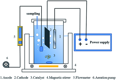
Electrochemical degradation of diuron was performed in a 0.35 L undivided cell that was placed in a water bath with a magnetic stirrer and under a constant current supplied by a Keysight U2722A USB modular source measure unit. The graphite-felt (6 cm × 12 cm) and Pt foil (1 cm × 6 cm) were employed as the cathode and anode, respectively. The oxidation experiment was conducted in an aqueous solution of 10 mg L−1 diuron with a total volume of 300 mL and sodium sulfate (0.05 M) was added into the solution as the electrolyte. The experimental reactor used in the test is shown in Fig. 1. H2SO4 and NaOH were used to adjust the pH of the solution. The concentration of diuron was determined by high performance liquid chromatography (HPLC, Waters 1525, USA) with a Waters 2489 UV/Visible detector equipped with an HSS T3, 5 μm, 250 mm × 4.6 mm (id) column. The mobile phase was a mixture composed of methanol and water (65![[thin space (1/6-em)]](https://www.rsc.org/images/entities/char_2009.gif) :
:![[thin space (1/6-em)]](https://www.rsc.org/images/entities/char_2009.gif) 30, v/v), and its flow rate was 0.95 mL min−1. The selected detection wavelength was 254 nm and the column temperature was 40 °C.
30, v/v), and its flow rate was 0.95 mL min−1. The selected detection wavelength was 254 nm and the column temperature was 40 °C.
2.4 Analytical methods
Field emission scanning electron microscopy (SEM, Cambridge S-360, UK) was used for the morphology characterization of the activated carbon catalyst. The total iron concentration was analyzed on a UV-vis spectrophotometer (Agilent Cary 100, USA) at λmax = 510 nm using the 1,10-phenanthroline method. The structure of the activated carbon catalyst was determined by X-ray diffraction (XRD, Bruker AXS D8 Advance, Germany). X-ray photoelectron spectra (XPS, ESCALAB 250, USA) analysis was used to investigate the surface composition of the activated carbon catalyst and the oxidation states of the iron species. VSM (VSM, PPMS-9, USA) was used to determine the magnetic properties of the catalyst. The specific surface area of the catalyst before and after PTFE modification was characterized by BET (BET, ASAP2020, USA). The water contact angle on the catalyst surface was measured by a contact angle meter (JY-82B, China). The diuron concentration was determined by high performance liquid chromatography (HPLC, Waters 1525, USA).3. Results and discussion
3.1 Characterizations of the modified activated carbon catalyst
Fig. 2 shows the surface morphology of the catalyst before and after modification with 5% PTFE. It can be seen that the surface of the catalyst becomes slightly smooth after modification with 5% PTFE and the structure of the PTFE on the catalyst surface after modification can be seen clearly. This dense polymer membrane can effectively prevent the dissolution of iron and deactivation due to ferric ion complexation.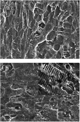 | ||
| Fig. 2 SEM micrographs of (a) before PTFE modification, (b) after 5% PTFE modification. (c) Higher resolution images of (b). | ||
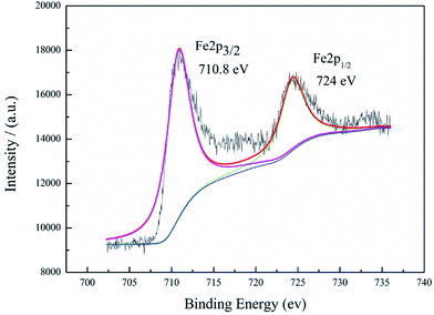
XPS, an important method to identify a material's composition, was used to characterize the surface elements of the activated carbon catalyst. It can be clearly observed from Fig. 3 that there are two main peaks at 710.8 eV and 724 eV, agreeing with those of Fe 2p3/2 and Fe 2p1/2, respectively. The results are in accordance with the standard Fe3O4 XPS spectra.33 This indicates that iron was successfully loaded on the activated carbon substrate.
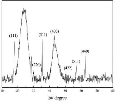
Fig. 4 shows the XRD results, which are consistent with those mentioned in the literature. Characteristic peaks were observed at 220, 311, 400, 511 and 440 at 2θ of 30.1, 35.4, 43.1, 56.9 and 62.5, which indicates the successful synthesis of the magnetic activated carbon catalyst.
ESI Fig. 1† shows the room temperature magnetization curves of the catalyst before and after modification with 5% PTFE. The saturation magnetization (Ms) of the catalyst is 0.26 emu g−1, decreasing to 0.11 emu g−1 after modification, and the existence of PTFE may decrease magnetic properties of the catalyst.
3.2 Effect of PTFE percentage
PTFE, a macromolecule material with properties such as corrosion resistance, chemical stability and thermo stability, can adapt to most kinds of complex electrochemical conditions. Therefore, it would be a good material to protect the activated carbon catalyst. The active component in the activated carbon catalyst may complex with the intermediate during the degradation of diuron, resulting in the deactivation of the catalyst. PTFE was chosen to modify the surface of the activated carbon catalyst to protect the active components of the catalyst. The effects of PTFE percentage (5% wt, 10% wt, 15% wt and 20% wt) on diuron degradation were investigated and the results are shown in Fig. 5. The experiment related to the persistence of the modified and unmodified catalysts is presented in the following sections.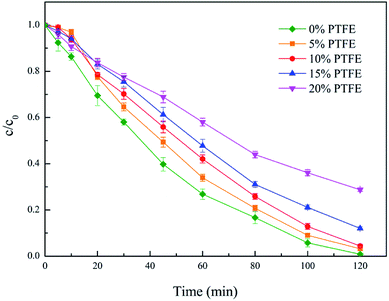 | ||
| Fig. 5 Effect of PTFE percentage. Conditions: I = 100 mA, pH 6.7 ± 0.2, catalyst 6 g L−1, 300 mL diuron 10 mg L−1. | ||
It can be seen that the degradation efficiency was slower during the first 15 minutes of the reaction, which may be because the degradation of diuron by the activated carbon catalysts is a simultaneous process of adsorption and degradation.
Before the power supply, aeration was performed for 15 minutes to increase the dissolved oxygen in the solution. After the aeration, the diuron adsorbed on the activated carbon in the period of the aeration was firstly degraded, which led to a slower degradation efficiency in the pre-reaction period. As the PTFE concentration increased, the adsorption effect of activated carbon weakened and the oxidation efficiency also declined rapidly. It can be seen from Fig. 5 that the degradation effect of diuron with 5% PTFE modified catalyst was almost the same as that of the 10% PTFE modified catalyst, and on account of energy-saving and catalytic efficiency, the catalyst surface was modified with 5% PTFE and applied to the subsequent experiments.
In addition, it can be observed from Fig. 5 that the diuron removal efficiency reached 99–100% with the unmodified catalyst in 2 h, while removal efficiency of around 95% was obtained with the modified catalyst within 2 h, indicating that the efficiency of the catalyst is lower than that without PTFE modification. The adsorption performance of the activated carbon catalyst is directly related to its degradation effect on diuron. This conjecture was verified by characterizing the contact angle and surface area of the catalyst before and after the PTFE modification. The test results are shown in Table 1.
| Catalyst | SBET (m2 g−1) | Water contact angle |
|---|---|---|
| Before modification | 223.24 | 59.7° |
| After modification | 54.54 | 114.5° |
A large area of graphite felt was used as the cathode in the system, which may adsorb organics during the oxidation process. In order to determine the adsorption ability of the graphite cathode for diuron, the adsorption experiment without catalyst at 100 mA was conducted in a separate reactor. The results showed that 10% of diuron was adsorbed by the graphite cathode after 2 h of reaction (ESI Fig. 1†).
As shown in Table 1, the surface area and hydrophilicity of the catalyst changed significantly after modification with 5% PTFE. The surface area of the catalyst reduced from 223.24 m2 g−1 to 54.54 m2 g−1 after modification. The water contact angle of the catalyst increased from 59.7° to 114.5° after modification, indicating that the catalyst changed from relatively hydrophilic to hydrophobic after PTFE modification. These changes in the properties reduced iron leaching and weakened the adsorption capacity during the oxidation process. In addition, direct adsorption experiments were used to verify this conclusion, the catalyst without modification could adsorb approximately 25% of diuron in 2 h under the conditions of pH = 6.7 ± 0.2, catalyst 3 g L−1, 300 mL diuron 10 mg L−1, and the modified catalyst could only adsorb 12% of diuron.
3.3 Effect of activated carbon catalyst loading
The dosage of the catalyst is an important parameter of hydroxyl radical produced by heterogeneous Fenton reaction and has a direct impact on the efficiency of the Fenton system. It negatively affects the efficiency of the EF process unless the catalyst concentration is suitable. Therefore, the impact of the modified catalyst dosage on the degradation of diuron was investigated in the range of 0.1–6 g L−1, and the results are presented in Fig. 6. It could be observed that the removal efficiency of diuron was enhanced as the dosage of catalyst increased. A lower catalyst dosage would lead to less and slower generation of hydroxyl radical. With the increase of catalyst dosage, the increased generation of hydroxyl radical resulted in a promotion in efficiency. When the quantity of catalyst increased from 3 g L−1 to 6 g L−1, there were almost no changes in the degradation of diuron. This phenomenon may be due to the active site involved in the reaction in the activated carbon catalyst being sufficient, so it could no longer improve the reaction efficiency by increasing the amount of catalyst. The modified activated carbon catalyst loading of 3 g L−1 was selected as the best degradation condition for cost reasons.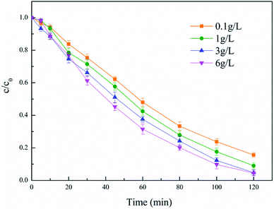 | ||
| Fig. 6 Effect of catalyst loading. Conditions: 5% PTFE modified, I = 100 mA, pH 6.7 ± 0.2, 300 mL diuron 10 mg L−1. | ||
3.4 Effect of current intensity
The current intensity is an important parameter that determines anodic oxidation and the generation of hydrogen peroxide, which has a great impact on the electro-Fenton system. For the purpose of investigating the influence of this parameter on diuron degradation, currents ranging from 25 to 150 mA were applied to the electro-Fenton system. The results are presented in Fig. 7. It could be observed that the degradation of diuron was improved obviously with the increase of the current intensity. Fig. 7 indicates that for the applied current in the range 25–100 mA, the degradation efficiency increased with the gradually increased applied current. The increase of current accelerated the generation and accumulation of hydrogen peroxide and also promoted the conversion from Fe3+ to Fe2+, which regenerates ferrous iron to catalyze the Fenton reaction (eqn (3)).| Fe3+ + e− → Fe2+ | (3) |
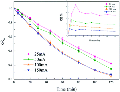 | ||
| Fig. 7 Effect of current intensity. Conditions: 5% PTFE modified, catalyst 3 g L−1, pH 6.7 ± 0.2, 300 mL diuron 10 mg L−1. | ||
When the current was increased from 100 mA to 150 mA, the degradation efficiency of diuron was not improved. As mentioned in many papers,34,35 the rate of H2O2 formation on graphite felt is affected by the applied current. With the continuous increasing of the current, the amount of hydrogen peroxide generated at the cathode was no longer enhanced, and even breaks down, which limits the efficiency of the Fenton reaction. Besides, the excessively increased current could cause an increase in side reactions.36 This helps to explain why the removal efficiency of diuron stayed the same when the current increased from 100 mA to 150 mA.
On the other side, the current efficiency (CE) at 25 mA, 50 mA, 100 mA, and 150 mA was calculated by the following equation:
It could be seen that the current efficiency decreased significantly as the current increased. Considering both current efficiency and diuron removal efficiency, 100 mA was chosen as the optimum current.
3.5 Effect of initial pH
It is well known that ferric species will form precipitates as ferric hydroxide under alkaline conditions, which is detrimental to establishing a good redox system between H2O2 and Fe2+/Fe3+.37 Heterogeneous catalysts may overcome this drawback of homogeneous systems but only for acidic conditions. The effect of initial pH on the degradation of diuron solutions during the heterogeneous electro-Fenton treatment with the modified activated carbon catalyst was examined.As can be seen in Fig. 8, with the increase of pH, the removal efficiency of diuron decreased. Although under neutral (pH = 6.7) and alkaline conditions (pH = 9), the removal efficiency of diuron had a significant decline compared with acidic conditions (pH = 3), the diuron removal rate still reached 95% after two hours of degradation. These results point out that pH = 3 corresponds to the optimum pH conditions for the EF process but, at the same time, the catalyst could be active under neutral and weak alkaline conditions, and maintained high efficiency, achieving the purpose of broadening the applicable pH range for Fenton's reaction. Furthermore, it is meaningful for the application of heterogeneous EF for the actual wastewater that is near neutral or weakly alkaline.
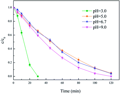 | ||
| Fig. 8 Effect of initial pH. Conditions: 5% PTFE modified, I = 100 mA, catalyst 3 g L−1, 300 mL diuron 10 mg L−1. | ||
Acidic pH was advantageous to the formation of hydrogen peroxide as well as anodization, which increased the reaction efficiency of the entire electro-Fenton process. In addition, acidic conditions cause a greater loss of iron (0.8 mg L−1) from the activated carbon catalyst, which also accelerates the degradation of diuron. However, the leaching of iron is not conducive to the durability of the catalyst and effluent quality. On the contrary, the leaching of iron from the modified catalyst is extremely low under neutral conditions (<0.1 mg L−1). This may help to explain the low oxidation efficiency in neutral conditions.
3.6 Effect of diuron concentration
The impact of the initial diuron concentration on the degradation process was investigated from 5 mg L−1 to 20 mg L−1, and the results are presented in Fig. 9. It can be seen from the figure that the diuron removal rate decreased slightly with increasing initial diuron concentration. It is worth mentioning that the removal of diuron was basically the same with diuron concentrations of 10 mg L−1 and 15 mg L−1. This phenomenon may be due to the low diuron concentration in the solution reducing the probability of oxidation at the active site of the catalyst during the reaction progress. At a diuron concentration of 10 mg L−1, the hydroxyl radical generated in the reaction was excessive and the removal rate of diuron was controlled by the excess hydroxyl radicals. Moreover, it was clear that the employment of greater initial pollutant content led to the greater removal of pollutants per unit of time, i.e. higher pollutant removal rates,38 and resulted in almost the same removal rates of 10 mg L−1 and 15 mg L−1. As the diuron concentration further increases, the increased diuron molecules enhance competition with the limited hydroxyl radicals in solution, which reduces the removal of diuron.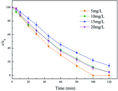 | ||
| Fig. 9 Effect of diuron concentration. Conditions: 5% PTFE modified, I = 100 mA, catalyst 3 g L−1, pH 6.7 ± 0.2. | ||
3.7 Catalyst reusability test
The reusability of the catalyst is an important advantage of the heterogeneous EF compared to the homogeneous EF. In the practical application process, the catalyst should have the ability to be separated from the effluent easily and reused several times without activity loss. Therefore, the long-term stability of the catalyst is quite important, which helps to save costs and stabilize the effluent quality.In order to investigate whether the PTFE modification enhances the stability and durability of the catalyst, we ran the 5% PTFE-modified catalyst and unmodified catalyst continuously for ten times under the same conditions. After each experiment, the catalyst was separated from the solution by filtration, washed with ultrapure water and dried at 80 °C for the next use. As Fig. 10 shows, after 10 consecutive uses of the unmodified catalyst, the removal efficiency of diuron dropped significantly and the removal rate decreased by about 8%. Obviously, the apparent downward trend of the unmodified catalyst indicated that PTFE modification indeed protects the catalyst from deactivation owing to the complexation with some iron complexing reagents39 and improves the durability of the catalyst.
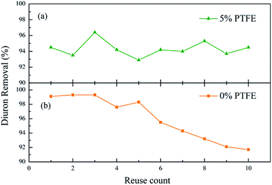 | ||
| Fig. 10 Reuse of catalyst. Conditions: 5% PTFE modified, I = 100 mA, catalyst 3 g L−1, pH 6.7 ± 0.2, 300 mL diuron 10 mg L−1. | ||
Moreover, it is worth mentioning that the leaching of ferric ions from the modified catalyst was less than 0.1 mg L−1 in ten consecutive degradation experiments, which is far below the EU emission standards (<2 ppm).40
4. Conclusions
To summarize, we provide an effective and simple method using activated carbon supported magnetic iron oxide (Fe3O4) as a solid catalyst for the heterogeneous electro-Fenton process. Moreover, the durability of the catalyst is significantly increased by modifying the surface of the catalyst with PTFE. In addition, we can obtain these conclusions in the degradation test for diuron:- This work verifies the feasibility of the degradation of diuron under near neutral pH condition in heterogeneous electro-Fenton system using modified catalysts. 95% removal for 10 mg L−1 diuron could be achieved within 2 h under the conditions of modified catalysts 3 g L−1, current intensity 100 mA and initial pH 6.7.
- Comparing the performances of the activated carbon catalyst modified by PTFE and the unmodified catalyst in ten continuous degradation experiments, the modified catalyst showed good stability, which indicated that the modification of the catalyst by PTFE was successful. In addition, the catalyst modified with 5% PTFE exhibited the advantages of good stability and catalytic activity, increasing the possibility for the practical application of heterogeneous EF.
- The range of pH suitable for electro-Fenton reaction has been significantly broadened. The modified catalyst still presents good performance in neutral or alkaline conditions. The leaching of ferric ions from the modified catalyst was less than 0.1 mg L−1 in ten consecutive degradation experiments, which is far below the EU emission standards (<2 ppm).
Conflicts of interest
There are no conflicts to declare.Acknowledgements
This work was supported by the National Natural Science Foundation of China (51778013 and 51478014) and the Cultivation Fund for Beijing New Century Hundred, Thousand and Ten Thousand Talents Project.References
- D. C. Gooddy, P. J. Chilton and I. Harrison, Sci. Total Environ., 2002, 297(1–3), 67–83 CrossRef PubMed.
- J. A. Field, R. L. Reed, T. E. Sawyer and M. Martinez, J. Agric. Food Chem., 1997, 45(10), 3897–3902 CrossRef.
- C. Bouquet-Somrani, F. Fajula, A. Finiels, P. Graffin, P. Geneste and J. L. Olive, New J. Chem., 2000, 24(12), 999–1002 RSC.
- P. E. Stackelberg, J. Gibs, E. T. Furlong, M. T. Meyer, S. D. Zaugg and R. L. Lippincott, Sci. Total Environ., 2007, 377(2–3), 255–272 CrossRef PubMed.
- S. Cannamichaelidou and A. S. Nicolaou, Sci. Total Environ., 1996, 193(1), 27–35 CrossRef.
- H. Katsumata, M. Sada, Y. Nakaoka, S. Kaneco, T. Suzuki and K. Ohta, J. Hazard. Mater., 2009, 171(1–3), 1081–1087 CrossRef PubMed.
- W. Khongthon, G. Jovanovic, A. Yokochi, P. Sangvanich and V. Pavarajarn, Chem. Eng. J., 2016, 292, 298–307 CrossRef.
- M. A. Oturan, N. Oturan, M. C. Edelahi, F. I. Podvorica and K. E. Kacemi, Chem. Eng. J., 2011, 171(1), 127–135 CrossRef.
- M. Quirantes, R. Nogales and E. Romero, J. Hazard. Mater., 2017, 331, 300–308 CrossRef PubMed.
- G. B. Ortiz De La Plata, O. M. Alfano and A. E. Cassano, Appl. Catal., B, 2010, 95(1–2), 1–13 CrossRef.
- E. Brillas, I. Sirés and M. A. Oturan, Chem. Rev., 2009, 109(12), 6570–6631 CrossRef PubMed.
- V. Kavitha and K. Palanivelu, Water Res., 2005, 39(13), 3062–3072 CrossRef PubMed.
- G. Ren, M. Zhou, M. Liu, L. Ma and H. Yang, Chem. Eng. J., 2016, 298, 55–67 CrossRef.
- H. Zhao, L. Qian, Y. Chen, Q. Wang and G. Zhao, Chem. Eng. J., 2018, 332, 486–498 CrossRef.
- L. Labiadh, M. A. Oturan, M. Panizza, N. B. Hamadi and S. Ammar, J. Hazard. Mater., 2015, 297, 34–41 CrossRef PubMed.
- M. Sun, M. Qiao, J. Wang and L. Zhai, ACS Sustainable Chem. Eng., 2017, 5(9), 7832–7839 CrossRef.
- P. V. Nidheesh, RSC Adv., 2015, 5(51), 40552–40577 RSC.
- P. V. Nidheesh, R. Gandhimathi, S. Velmathi and N. S. Sanjini, RSC Adv., 2014, 4(11), 5698–5708 RSC.
- H. Zhao, Q. Wang, Y. Chen, Q. Tian and G. Zhao, Carbon, 2017, 124, 111–122 CrossRef.
- H. Zhao, L. Qian, Y. Chen, Q. Wang and G. Zhao, Chem. Eng. J., 2018, 332, 486–498 CrossRef.
- E. G. Garrido-Ramírez, B. K. G. Theng and M. L. Mora, Appl. Clay Sci., 2010, 47(3–4), 182–192 CrossRef.
- N. Sanabria, A. álvarez, R. Molina and S. Moreno, Catal. Today, 2008, 133–135, 530–533 CrossRef.
- S. Navalon, A. Dhakshinamoorthy, M. Alvaro and H. Garcia, ChemSusChem, 2011, 4(12), 1712–1730 CrossRef PubMed.
- F. Martínez, M. I. Pariente, J. Á. Botas, J. A. Melero and A. Rubalcaba, J. Chem. Technol. Biotechnol., 2012, 87(7), 880–886 CrossRef.
- J. A. Melero, F. Martínez, J. A. Botas, R. Molina and M. I. Pariente, Water Res., 2009, 43(16), 4010–4018 CrossRef PubMed.
- H. Lim, J. Lee, S. Jin, J. Kim, J. Yoon and T. Hyeon, Chem. Commun., 2006,(4), 463–465 RSC.
- E. V. Kuznetsova, E. N. Savinov, L. A. Vostrikova and V. N. Parmon, Appl. Catal., B, 2004, 51(3), 165–170 CrossRef.
- M. Neamu, C. Catrinescu and A. Kettrup, Appl. Catal., B, 2004, 51(3), 149–157 CrossRef.
- R. Gonzalez-Olmos, M. J. Martin, A. Georgi, F. Kopinke, I. Oller and S. Malato, Appl. Catal., B, 2012, 125, 51–58 CrossRef.
- T. D. Nguyen, N. H. Phan, M. H. Do and K. T. Ngo, J. Hazard. Mater., 2011, 185(2–3), 653–661 CrossRef PubMed.
- W. P. Kwan and B. M. Voelker, Environ. Sci. Technol., 2003, 37(6), 1150–1158 CrossRef PubMed.
- K. Waterston, J. W. Wang, D. Bejan and N. J. Bunce, J. Appl. Electrochem., 2006, 36(2), 227–232 CrossRef.
- Q. Feng, S. Li, W. Ma, H. Fan, X. Wan, Y. Lei, Z. Chen, J. Yang and B. Qin, J. Alloys Compd., 2018, 737, 197–206 CrossRef.
- M. Panizza and M. A. Oturan, Electrochim. Acta, 2011, 56(20), 7084–7087 CrossRef.
- A. özcan, M. A. Oturan, N. Oturan and Y. Sahin, J. Hazard. Mater., 2009, 163(2–3), 1213–1220 CrossRef PubMed.
- Y. Wang, Y. Liu, K. Wang, S. Song, P. Tsiakaras and H. Liu, Appl. Catal., B, 2015, 165, 360–368 CrossRef.
- L. Zhou, Z. Hu, C. Zhang, Z. Bi, T. Jin and M. Zhou, Sep. Purif. Technol., 2013, 111, 131–136 CrossRef.
- F. C. Moreira, R. A. R. Boaventura, E. Brillas and V. J. P. Vilar, Appl. Catal., B, 2017, 202, 217–261 CrossRef.
- J. Deng, J. Jiang, Y. Zhang, X. Lin, C. Du and Y. Xiong, Appl. Catal., B, 2008, 84(3–4), 468–473 CrossRef.
- S. Sabhi and J. Kiwi, Water Res., 2001, 35(8), 1994–2002 CrossRef PubMed.
Footnote |
| † Electronic supplementary information (ESI) available. See DOI: 10.1039/c8ra02776e |
| This journal is © The Royal Society of Chemistry 2018 |

