
 Open Access Article
 This Open Access Article is licensed under a
 Creative Commons Attribution 3.0 Unported Licence
MoO3−x-deposited TiO2 nanotubes for stable and high-capacitance supercapacitor electrodes†
Shupei Sun,
Yu Sun,
Jiang Wen,
Bo Zhang,
Xiaoming Liao *,
Guangfu Yin,
Zhongbing Huang and
Ximing Pu
*,
Guangfu Yin,
Zhongbing Huang and
Ximing Pu
College of Materials Science and Engineering, Sichuan University, Chengdu, Sichuan 610065, China. E-mail: sherman_xm@163.com; Fax: +86 28 85413003
First published on 13th June 2018
Abstract
Here we report the supercapacitive properties of a novel MoO3−x/TiO2 nanotube composite prepared by a facile galvanostatic deposition technique and subsequently thermal treatment in an argon atmosphere between 350 °C and 550 °C. X-ray diffraction and X-ray photoelectron spectroscopy confirm the existence of MoO3−x. The MoO3−x/TiO2 electrode prepared at 550 °C exhibits a high specific capacitance of 23.69 mF cm−2 at a scan rate of 10 mV s−1 and good cycling stability with capacitance retention of 86.6% after 1000 cycles in 1 M Na2SO4 aqueous solution. Our study reveals a feasible method for the fabrication of TiO2 nanotubes modified with electroactive MoO3−x as high-performance electrode materials for supercapacitors.
1. Introduction
In the past decade, various nanostructured materials (such as nanotubes,1,2 nanorods,3,4 nanowires,5,6 and nanofibers7) have been widely investigated because they possess ordered geometrical structure. In particular, TiO2 nanotubes (TNTs) with a well-defined open-top and uninterrupted nanotube structure have received tremendous attention in various applications including photocatalytic degradation of environmental pollutants,8 solar cells,9 energy storage devices,10 drug delivery11 and sensors.12 Supercapacitors are one of the most promising electrochemical energy-storage systems and have attracted tremendous attention.13–17 Recently, self-assembled titania nanotube arrays have received immense interest for use in supercapacitors because of their capability to offer large surface area for electrochemical reactions and unique electron transport pathways compared with non-oriented structures. Additionally, the electroactive materials can directly grow on the surface of TNTs, avoiding the use of a polymer binder and conductive additives.However, TiO2 is known as an intrinsic n-type semiconductor with a band gap of approximately 3.2 eV (for anatase phase) and 3.1 eV (for rutile phase).18 Pristine TNTs only contribute a very low capacitance (0.047–0.97 mF cm−2).19–22 Therefore, TiO2 nanotubes need to be modified urgently in order to meet the demands for supercapacitors with high electrochemical performance. A promising method to further enhance the capacitance of TNTs is to incorporate with some transition metal oxides (NiO,23 MnO2 (ref. 24 and 25) and MoO3 (ref. 26) etc.). The composite electrode can utilize the positive features of individual materials and may provide a combined effect, such as large capacitance and good cycling performance.27
Molybdenum oxides have enabled a wide range of applications in gas sensing,28 catalysts,29 electrochromic devices1 and energy storage30,31 due to their low cost, resource abundance and nontoxicity. In particular, a layered molybdenum trioxide (α-MoO3) has been studied as an attractive electrode material for supercapacitor due to its high theoretical specific capacitance of 1111 mA h g−1.32 However, the poor electrical conductivity and large capacitance loss in initial cycles have limited its application as an electrode material.26,33 Annealing in inert or hydrogen atmosphere could effectively improve electrical conductivity of some transition metal oxides.20,34 Meduri et al. discovered that oxygen deficient MoO3−x had fast intercalation and excellent electrochemical performance in lithium ion batteries.6 Law et al. reported that oxygen vacancies in MoO3−x led to enhanced electrical conductivity.35 Dunn et al. showed that incorporation of oxygen vacancies in MoO3−x could enhance pseudocapacitive charge storage properties.36 To the best of our knowledge, there have been a few studies on incorporating MoO3−x with TiO2 nanotubes and thus exploring its supercapacitive behavior. Compared with other hybrid electrodes,37–39 the prepared electrodes can make full use of TiO2 nanotubes and MoO3−x layer, thus achieving high electrochemical performance. Therefore, we fabricated MoO3−x/TiO2 nanotubes composite and extensively studied its application for supercapacitor.
In this work, a feasible approach was proposed to prepare MoO3−x/TiO2 nanotube hybrid by galvanostatic deposition in molybdenum salt solutions and subsequent thermal treatment in argon atmosphere. Various microstructure characterizations and electrochemical measurements were conducted to investigate the crystal phase, surface morphology, chemical composition and electrochemical properties of prepared samples. The electrochemical measurements reveal improved electrochemical performance of MoO3−x/TiO2 nanotubes composite with high specific capacitance as well as stable capacitance behavior.
2. Experimental procedure
2.1. Materials
The titanium sheet (TA2, purity > 99.6%, 10 × 10 × 1 mm3) was purchased from LuoKe titanium Ltd. Ethylene glycerol (C2H6O2, purity > 99.5%), ammonium fluoride (NH4F, purity > 96%), hexaammonium molybdate tetrahydrate ((NH4)6Mo7O24·4H2O, purity > 99.0%) and sodium sulfate anhydrous (Na2SO4, purity > 99.0%) were purchased from KeLong Chemical Ltd. Other chemical reagents used in these experiments were of analytical grade and were used directly without further purification. All aqueous solutions were prepared using deionized water.2.2. Fabrication of MoO3−x/TiO2
The highly ordered TNTs were prepared as described elsewhere.26 In order to enhance adhesion of nanotubes to titanium substrate and obtain crystalline TNTs, the prepared nanotubes were annealed at 450 °C for 1 h in ambient atmosphere. Then electrochemical deposition was carried out with a three-electrode system composed of annealed TNTs as the working electrode, a Pt foil as the counter electrode and an Ag/AgCl as the reference electrode. Galvanostatic depositions were carried out at a current density of 0.5 mA cm−2 for 5 min in 0.05 M (NH4)6Mo7O24·4H2O aqueous solution. Afterwards, the as-deposited samples were annealed at 350 °C, 450 °C, and 550 °C in argon atmosphere for 1 h. In consideration of tubular structure collapses at higher annealing temperatures (e.g. 650 °C), we just studied capacitive behavior of deposited samples annealed at 350–550 °C. The sample annealed at 450 °C is designated as M-TNT. For comparison, TNTs just annealed at 450 °C for 1 h in ambient atmosphere are referred as TNT.2.3. Materials characterization and electrochemical measurements
A Hitachi S-4800 scanning electron microscopy (SEM) and DX-2700 X-ray diffraction (XRD) were used to investigate the surface morphology and microstructure of the fabricated samples, respectively. Chemical composition and chemical states of deposited samples were characterized by X-ray photoelectron spectroscope (XPS, Escalab 250Xi, USA). Electrochemical measurements were performed in a 1 M Na2SO4 aqueous solution with an electrochemical workstation (CHI660E, China) in a 3-electrode setup consisting of the prepared sample as the working electrode, platinum foil as the counter-electrode, and saturated Ag/AgCl electrode as the reference electrode. Cyclic voltammetry (CV) tests were conducted over a voltage range from −0.9 to −0.2 V (vs. Ag/AgCl) at different scan rates (from 10 to 200 mV s−1). The galvanostatic charge–discharge (CD) testing was performed under different current densities (from 0.4 to 1 mA cm−2). Mott–Schottky plots were measured at a frequency of 1 kHz. Electrochemical impedance spectroscopy (EIS) measurements were conducted over a frequency range of 0.01 Hz to 100 kHz at an AC voltage amplitude of 5 mV. The cycling stability of the samples was tested by galvanostatic CD measurement performed up to 1000 cycles at a current density of 0.6 mA cm−2.3. Results and discussion
3.1. Morphology and structure analyses
The crystalline phase of prepared M-TNT was characterized by XRD. As shown in Fig. 1a, the diffraction peaks located at ∼25.3° and ∼48.0° are the characteristic peaks of anatase TiO2 (JCPDF 21-1272) while peaks at ∼38.4° and ∼40.1° are assigned to Ti (from Ti substrate). Notably, the peaks with 2θ of ∼28.5°, ∼29.4°, ∼30.9° and ∼32.6° are indexed to an oxygen deficient Mo17O47 phase (JCPDF 71-0566).6 Due to the strong sharp diffraction peaks of titanium substrate, the diffraction peaks corresponding to MoO3−x are suppressed. | ||
| Fig. 1 XRD pattern of M-TNT (a). XPS spectra of M-TNT: survey scan (b), Mo 3d (c) and Ti 2p (d) binding energy regions. | ||
Furthermore, XPS measurements were then carried out to determine valence states of M-TNT. In the survey spectrum (Fig. 1b), peaks of Mo and O are clearly observed, suggesting the presence of molybdenum oxides in the composite. Typical Mo 3d and Ti 2p spectra are shown in Fig. 1c and d, respectively. The Mo 3d5/2 peak at ∼231.6 and the Mo 3d3/2 peak at ∼235.1 eV correspond to Mo5+, and the Mo 3d3/2 peak at 232.4 eV corresponds to Mo4+, respectively.40 Our early research discovered that coating layer after electrochemical deposition in molybdenum salt solutions was just amorphous Mo5+ oxides and Mo6+ oxides.26 So, the formation of Mo4+ from M-TNT indicates that thermal treatment in argon atmosphere could lead to oxygen loss on the surface of deposition coating, resulting in the generation of oxygen deficiency and low oxidation states. This phenomenon has been previously observed in other reports.41,42 The peaks at ∼232.6 eV and ∼235.7 eV are indexed to 3d5/2 and 3d3/2 of Mo6+, respectively.43,44 Additionally, the Ti 2p3/2 peak at ∼458.6 eV and the Ti 2p1/2 peak at ∼464.3 eV correspond to Ti4+ (Fig. 2b),45 indicating the formation of TiO2. Therefore, in combination with above analysis we successfully prepared MoO3−x/TiO2 composite electrode material.
 | ||
| Fig. 2 SEM images of TNT (a) and M-TNT (b). | ||
Fig. 2 shows the surface morphology of TNT and M-TNT. From Fig. 2a, the anodized TNTs with high-density, well-ordered and uniform characteristics can be seen. The whole surface of the nanotubes is bare without any loading or coating. As shown in Fig. 2b, MoO3−x species are electrodeposited on the top of nanotubes to form a film-on-tube structure. Notably, some nanotubes still can be seen, which contribute to speedy permeation of electrolyte ions.
3.2. Electrochemical characterizations
To evaluate the electrochemical property of the MoO3−x/TiO2 nanocomposites, electrochemical measurements were performed with a three-electrode system in 1 M Na2SO4 electrolyte. For a comparison, the pristine TNTs were also intensively studied. Fig. 3a shows the CV curves for TNT and M-TNT samples collected at a scan rate of 50 mV s−1. The curve of TNT shows a strong dependence of current density on the applied potential. The decrease of current densities at higher potentials results in a sloping profile for TNT. Additionally, a larger area under CV curve and higher current response for M-TNT electrode indicate a markedly enhanced electrochemical performance after incorporating with MoO3−x. The shapes of these CV curves remain unchanged as the scan rates increase from 10 to 200 mV s−1, indicating good capacitive behavior and high-rate capability of M-TNT (Fig. S1a, ESI†). Fig. 3b shows the calculated areal capacitance of these electrodes as a function of scan rate. The areal capacitances of TNT and M-TNT are 2.26 mF cm−2 and 18.40 mF cm−2 at a scan rate of 50 mV s−1, respectively. Moreover, the sample M-TNT shows good rate capacitance. The specific capacitance of M-TNT drops from 20.44 to 16.92 mF cm−2 with a good retention of ∼82.78% of the initial capacitance with scan rates from 10 to 200 mV s−1. In contrast, the TNT sample retains only ∼74.0% of the initial capacitance. The enhanced rate capability is attributed to improved electrical conductivity of M-TNT. For all of the samples, the specific capacitance decreases with increasing scan rate, which is usually due to the limitation of charge accumulation at high scan rates.43 | ||
| Fig. 3 CV plots at a scan rate of 50 mV s−1 for TNT and M-TNT (a). Areal capacitances of samples measured as a function of scan rate (b). Galvanostatic CD curves at a current density of 0.4 mA cm−2 for TNT and M-TNT (c). Areal capacitances obtained at different current densities (d). | ||
As reported in literatures, the electrochemical performance of some transition metal oxides can be improved by introducing oxygen deficiency and oxygen non-stoichiometry via annealing in inert or hydrogen atmosphere.20,41,42,45,46 In our study, the generation of MoIV oxides and MoV oxides also can be ascribed to the oxygen depletion inside MoO3 network. In comparison with pristine TNTs, the enhanced capacitive performance of M-TNT is attributed to two major improvements upon incorporating with MoO3−x. First, the conductive MoO2 decreases the internal resistance of MoO3−x/TiO2 composite and enables fast charge flow to meet high-rate charge and discharge.47 Additionally, oxygen vacancies act as shallow donors and thereby increase the carrier concentration, hence improving electrical conductivity of electrode material.20,34,36,45 Second, a Na-intercalating MoO3 phase is favorable of intercalation and deintercalation of electrolyte ions, and thus enhancing electrochemical behavior.26,48
The electrochemical performance of M-TNT was further studied by galvanostatic CD tests, which were performed in the potential range from −0.9 to −0.2 V. Fig. 3c shows the charge/discharge curves of different electrodes collected at a current density of 0.4 mA cm−2. It is to be noted that the discharge time of M-TNT is longer than that of TNT at the same current density. The charge/discharge curves of M-TNT and TNT at different current densities are shown in Fig. S2.† Fig. 3d shows the specific capacitance obtained from galvanostatic CD test at various current densities. The M-TNT shows a remarkable areal capacitance of 21.08 mF cm−2 at a current density of 0.4 mA cm−2 and high-rate capability with capacitance retention of ∼89.42% as the current density increases from 0.4 to 1 mA cm−2. Additionally, the M-TNT shows a larger capacitance than that of TNT at each charge/discharge current density, which is consistent with the results obtained in the CV study.
EIS measurements were performed to study charge transfer and ions diffusion characteristic of prepared electrode materials. Fig. 4a shows typical Nyquist plots of TNT and M-TNT hybrid. The Nyquist plot of M-TNT exhibits a much lower impedance value than that of TNT. Fig. 4b shows the corresponding equivalent circuit of Nyquist plots. Rs is the bulk solution resistance and R3 is the charge–discharge resistance through the nanotubes; R1 and CPE1 are used to simulate the charge-transfer resistances and capacitances of the near-top regions of nanotubes, respectively. R2 and CPE2 values for the near-bottom regions of nanotubes, respectively.22 CPE-P is the constant phase element exponent. CPE-T is the capacitance when CPE-P = 1.49 W is defined by three following values. W-R is the diffusion resistance, W-T is the diffusion time constant, W-P is a fractional exponent, which has a value near 0.5 with regard to the finite length diffusion.50 Table 1 lists the fitted values for the elements of TNT and M-TNT. As for R2 and R3, the calculated values show no important variation before and after coated with MoO3−x, which is attributed to the unchanged structure of TiO2 as observed from XRD patterns and XPS spectra. Notably, R1 is obviously decreased from 110 Ω for TNT to 2.5 Ω for M-TNT, which is resulted from the additional deposition of MoO3−x layer on the surface of TiO2 nanotubes. The value of CPE1-T remains virtually the same in the two electrodes, suggesting a double layer capacitance.51 From Fig. S3,† the phase angle deviating from a perfect 90° confirms the existence of pseudocapacitance.45 Additionally, the small value of Warburg diffusion impedance indicates fast ion diffusion.50 The existence of conductive MoO2 and oxygen vacancies from MoO3−x enhances electrical conductivity, thus improving kinetics of ions transport in the electrode.
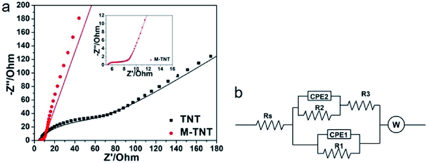 | ||
| Fig. 4 Nyquist plots (a) of TNT and M-TNT with insets showing an enlargement of high-frequency regions. The scattered dots and solid lines are the experimental and fit impedance data, respectively. The corresponding EIS equivalent circuit (b). | ||
| Equivalent circuit elements | Fitting values | |
|---|---|---|
| TNT | M-TNT | |
| Rs (Ω) | 3 | 5.1 |
| R1 (Ω) | 110 | 2.5 |
| CPE1-T | 7.352 × 10⁻⁶ | 2.399 × 10⁻⁶ |
| CPE1-P | 0.752 | 0.696 |
| R2 (Ω) | 110 | 110 |
| CPE2-T | 0.002 | 0.080 |
| CPE2-P | 0.141 | 0.145 |
| R3 (Ω) | 5 | 4.0 |
| W-R | 1031 | 5.197 |
| W-T | 0.119 | 0.020 |
| W-P | 0.479 | 0.426 |
The cyclic charge–discharge measurements were performed to evaluate the electrochemical durability of prepared electrodes. As shown in Fig. 5, the capacitance retentions for TNT and M-TNT are about 78.5% and 87.4% after 1000 cycles, respectively. Thereby, the higher specific capacitance and better cycling stability indicate that the MoO3−x/TiO2 is a promising electrode material.
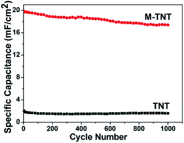 | ||
| Fig. 5 Cycle performance of TNT and M-TNT measured at a current density of 0.6 mA cm−2 up to 1000 cycles. | ||
The above-mentioned experimental results confirm the contribution of MoO3−x within composite electrode materials. As the formation of substoichiometric oxides is sensitive to thermal conditions, it motivated us to study the effect of annealing temperatures on the structure and electrochemical performance of MoO3−x/TiO2 hybrids. From XRD patterns (Fig. S4†), we discover peaks of crystalline MoO3−x tend to appear at higher temperatures (i.e. 450 °C and 550 °C). Compared with the sample annealed at 450 °C, the slight shift of MoO3−x peaks for the sample annealed at 550 °C is attributed to a change of lattice constant due to the oxygen vacancies.42 Additionally, the formation of the thermodynamically stable phase of TiO2 (i.e. rutile) indicates transformation of anatase to rutile when annealed at 550 °C. Fig. S5† shows SEM images of deposited samples annealed at 350 °C and 550 °C. According to XPS analyses (Fig. S6 and Table S1†), higher amount of Mo5+ and Mo4+ for sample annealed at 550 °C suggests a larger concentration of oxygen vacancies. In order to obtain a better understanding of the effect of annealing temperatures on electrical properties, Mott–Schottky plots were drawn based on capacitances derived from the imaginary part of the impedance at each potential with 1 kHz frequency. The calculated carrier densities of deposited samples annealed at 350 °C, 450 °C and 550 °C are 7.14 × 1017 cm−3, 3.12 × 1019 cm−3, 7.31 × 1019 cm−3, respectively (Fig. 6a). Mott–Schottky studies reveal 2 orders of magnitudes enhancement of carrier density when the annealing temperature increases from 350 to 550 °C, which is possibly due to the improved crystallinity of MoO3−x as well as the creation of oxygen vacancy states. Fig. 6b and c shows CV plots at a scan rate of 50 mV s−1 and areal capacitances obtained as a function of scan rate, respectively. As expected, the deposited sample annealed at 550 °C yields the highest areal capacitance of 23.69 mF cm−2 at a scan rate of 10 mV s−1. The EIS analysis indicates that the sample annealed at 550 °C has good charge transfer performance and ion diffusion capability (Fig. 6d). Fig. S7† shows the galvanostatic CD curves for samples annealed at different temperatures and areal capacitances obtained at different current densities. The areal capacitances for deposited samples annealed at 350 °C and 550 °C are 14.57 mF cm−2 and 24.74 mF cm−2 at a current density of 0.4 mA cm−2, respectively. We also performed cycling measurements to examine the long-term stability of these MoO3−x/TiO2 nanotube composites (Fig. 7). The capacitance retention of composite electrodes prepared at 350 °C and 550 °C are 80.9% and 86.6%, respectively. From ESI (Table S1†), we can observe the existence of MoO3 for all samples. Our previous study discovered that detachment of MoO3 and structure change led to the rapid capacity decay (∼12%) in the initial cycles.26 Although oxygen vacancies are capable to stabilize the crystalline structure during cycling, the suitable concentration of oxygen deficiency plays an important role in achieving good cycling performance.36,40 Hence, the sample prepared at 450 °C exhibits better cycling stability than those of others. Additionally, a fluctuation in the specific capacitance during cycling is possibly due to “activation process”52,53 and the uneven electrolyte wetting of the phases of MoO2 and MoO3.40
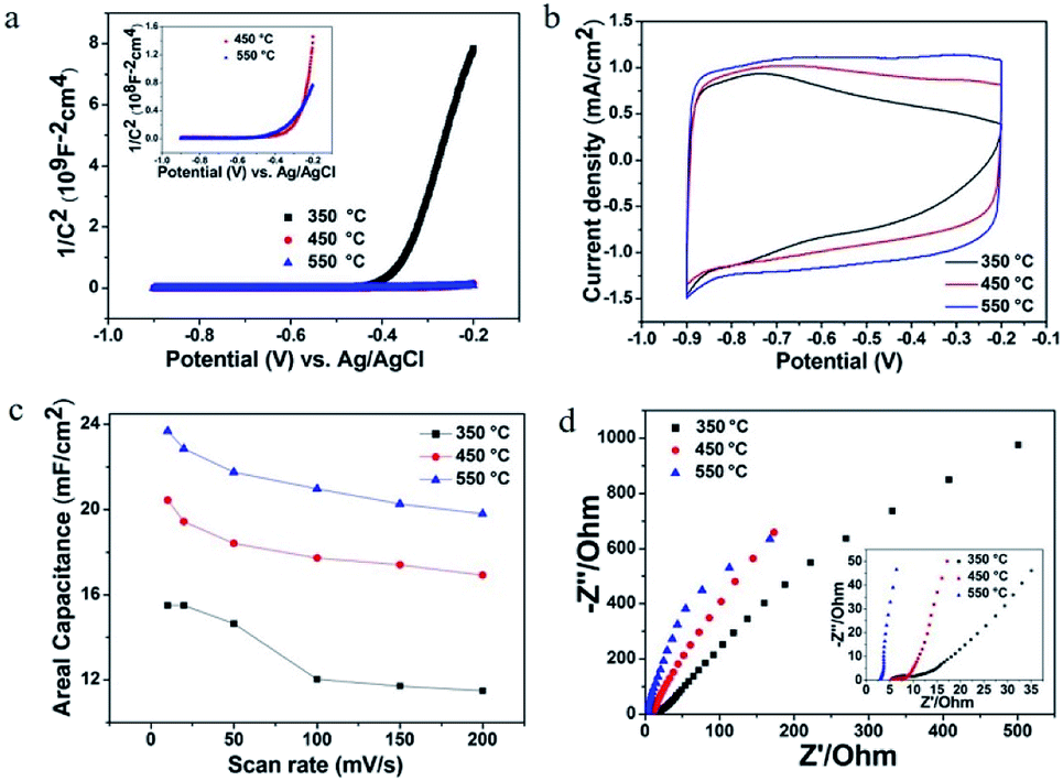 | ||
| Fig. 6 Mott–Schottky plots for samples at different annealing temperatures (a). CV plots at a scan rate of 50 mV s−1 (b), areal capacitances obtained as a function of scan rate (c) and Nyquist plots (d) for deposited samples annealed at different temperatures. | ||
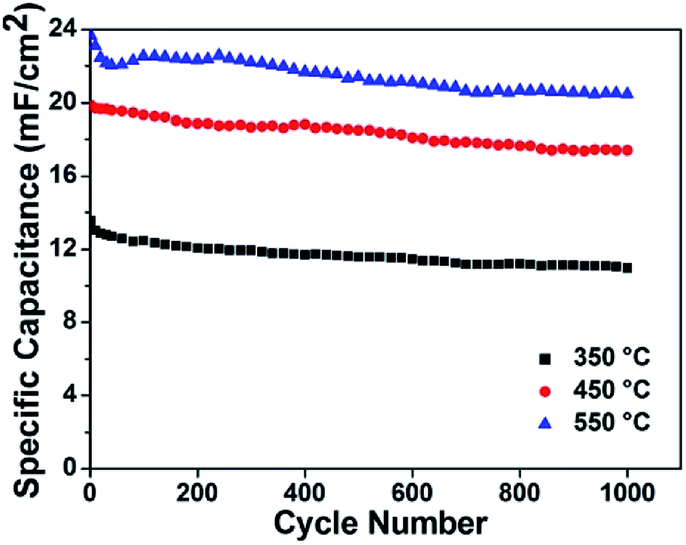 | ||
| Fig. 7 Cycle performance of these samples measured at a current density of 0.6 mA cm−2 up to 1000 cycles. | ||
4. Conclusion
In our study, MoO3−x/TiO2 nanotube composites were synthesized by galvanostatic depositions and then annealed in argon atmosphere. Electrochemical measurements confirm the contribution of MoO3−x and enhancement in capacitive performance within composite electrode materials. We also have demonstrated that the electrochemical properties of MoO3−x/TiO2 nanotube composites can be enhanced by controlling annealing temperatures. The electrode prepared at 550 °C yields highest specific capacitance of 24.74 mF cm−2 at a current density of 0.4 mA cm−2 and good capacitance retention (86.6%) even after 1000 continuous charge–discharge cycles in Na2SO4 electrolyte. The ease of synthesis and exceptional electrochemical properties suggest MoO3−x/TiO2 nanotube is a promising supercapacitor electrode material.Conflicts of interest
There are no conflicts to declare.Acknowledgements
The work was financially supported by the Fundamental Research Funds for the Central Universities (2012017yjsy163). S. P. Sun is very much grateful to Lingzhu Yu from the National Engineering Research Center for Biomaterials, Sichuan University for the assistance with the microscopy work. S. P. Sun thanks Mr Yongsheng Yan for his encouragement and support during the research.References
- D. D. Yao, M. R. Field, A. P. O'Mullane, K. Kalantar-zadeh and J. Z. Ou, Nanoscale, 2013, 5, 10353–10359 RSC.
- A. Izadi-Najafabadi, T. Yamada, D. N. Futaba, M. Yudasaka, H. Takagi, H. Hatori, S. Iijima and K. Hata, ACS Nano, 2011, 5, 811–819 CrossRef PubMed.
- X. H. Lu, D. Z. Zheng, T. Zhai, Z. Q. Liu, Y. Y. Huang, S. L. Xie and Y. X. Tong, Energy Environ. Sci., 2011, 4, 2915–2921 Search PubMed.
- S.-Z. Chu, S. Inoue, K. Wada, S. Hishita and K. Kurashima, Adv. Funct. Mater., 2005, 15, 1343–1349 CrossRef.
- M. K. Faruque, K. M-Darkwa, Z. G. Xu and D. Kumar, Appl. Surf. Sci., 2012, 260, 36–41 CrossRef.
- P. Meduri, E. Clark, J. H. Kim, E. Dayalan, G. U. Sumanasekera and M. K. Sunkara, Nano Lett., 2012, 12, 1784–1788 CrossRef PubMed.
- C. Merino, P. Soto, E. Vilaplana-Ortego, J. M. G. d. Salazar, F. Pico and J. M. Rojo, Carbon, 2005, 43, 551–557 CrossRef.
- Q. Zheng, H.-J. Lee, J. Lee, W. Choi, N.-B. Park and C. Lee, Chem. Eng. J., 2014, 249, 285–292 CrossRef.
- Q. Y. Wang, S. Li, J. L. Qiao, R. C. Jin, Y. F. Yu and S. M. Gao, Sol. Energy Mater. Sol. Cells, 2015, 132, 650–654 CrossRef.
- A. Lamberti, N. Garino, A. Sacco, S. Bianco, A. Chiodoni and C. Gerbaldi, Electrochim. Acta, 2015, 151, 222–229 CrossRef.
- L. H. Shi, H. Xu, X. M. Liao, G. F. Yin, Y. D. Yao, Z. B. Huang, X. C. Chen and X. M. Pu, J. Alloys Compd., 2015, 647, 590–595 CrossRef.
- J. J. Liao, S. W. Lin, Y. Yang, K. Liu and W. C. Du, Sens. Actuators, B, 2015, 208, 457–463 CrossRef.
- B. D. Boruah, S. Nandi and A. Misra, ACS Appl. Energy Mater., 2018, 1(4), 1567–1574 CrossRef.
- B. D. Boruah, A. Maji and A. Misra, ACS Appl. Mater. Interfaces, 2018, 10, 15864–15872 Search PubMed.
- B. D. Boruah and A. Misra, ACS Energy Lett., 2017, 2, 1720–1728 CrossRef.
- B. D. Boruah and A. Misra, J. Mater. Chem. A, 2016, 4, 17552–17559 Search PubMed.
- B. D. Boruah, A. Maji and A. Misra, Nanoscale, 2017, 9, 9411–9420 RSC.
- A. Bendavid, P. J. Martin, A. Jamting and H. Takikawa, Thin Solid Films, 1999, 355, 6–11 CrossRef.
- Y. B. Xie, Y. Wang and H. X. Du, J. Mater. Sci. Eng. B, 2013, 178, 1443–1451 CrossRef.
- X. H. Lu, G. M. Wang, T. Zhai, M. H. Yu, J. Y. Gan, Y. X. Tong and Y. Li, Nano Lett., 2012, 12, 1690–1696 CrossRef PubMed.
- H. Wu, D. D. Li, X. F. Zhu, C. Y. Yang, D. F. Liu, X. Y. Chen, Y. Song and L. F. Lu, Electrochim. Acta, 2014, 116, 129–136 CrossRef.
- H. Zhou and Y. R. Zhang, J. Phys. Chem. C, 2014, 118, 5626–5636 Search PubMed.
- J.-H. Kim, K. Zhu, Y. F. Yan, C. L. Perkins and A. J. Frank, Nano Lett., 2010, 10, 4099–4104 CrossRef PubMed.
- J. Q. Liu, J. Xu, Y. Wang, J. W. Cui, H. H. Tan and Y. C. Wu, RSC Adv., 2017, 7, 31512–31518 RSC.
- Y.-G. Huang, X.-H. Zhang, X.-B. Chen, H.-Q. Wang, J.-R. Chen, X.-X. Zhong and Q.-Y. Li, Int. J. Hydrogen Energy, 2015, 40, 14331–14337 CrossRef.
- S. P. Sun, X. M. Liao, Y. Sun, G. F. Yin, Y. D. Yao, Z. B. Huang and X. M. Pu, RSC Adv., 2017, 7, 22983–22989 RSC.
- A. Ramadoss and S. J. Kim, Int. J. Hydrogen Energy, 2014, 39, 12201–12212 CrossRef.
- L. Q. Wang, P. Gao, D. Bao, Y. Wang, Y. J. Chen, C. Chang, G. B. Li and P. P. Yang, Cryst. Growth Des., 2014, 14, 569–575 Search PubMed.
- L. J. Yang, W. J. Zhou, D. M. Hou, K. Zhou, G. Q. Li, Z. H. Tang, L. G. Li and S. W. Chen, Nanoscale, 2015, 7, 5203–5208 RSC.
- X. Zhang, X. Z. Zeng, M. Yang and Y. X. Qi, ACS Appl. Mater. Interfaces, 2014, 6, 1125–1130 Search PubMed.
- Z. Y. Wang, S. Madhavi and X. W. Lou, J. Phys. Chem. C, 2012, 116, 12508–12513 Search PubMed.
- H. Li, P. Balaya and J. Maier, J. Electrochem. Soc., 2004, 151, A1878–A1885 CrossRef.
- B. Ahmed, M. Shahid, D. H. Nagaraju, D. H. Anjum, M. N. Hedhili and H. N. Alshareef, ACS Appl. Mater. Interfaces, 2015, 7, 13154–13163 Search PubMed.
- M. Salari, K. Konstantinov and H. K. Liu, J. Mater. Chem., 2011, 21, 5128–5133 RSC.
- D. O. Scanlon, G. W. Watson, D. J. Payne, G. R. Atkinson, R. G. Egdell and D. S. L. Law, J. Phys. Chem. C, 2010, 114, 4636–4645 Search PubMed.
- H.-S. Kim, J. B. Cook, H. Lin, J. S. Ko, S. H. Tolbert, V. Ozolins and B. Dunn, Nat. Mater., 2017, 16, 454–460 CrossRef PubMed.
- N. Li, Y. M. Li, W. J. Li, S. D. Ji and P. Jin, J. Phys. Chem. C, 2016, 120, 3341–3349 Search PubMed.
- V. K. Mariappan, K. Krishnamoorthy, P. Pazhamalai, S. Sahoo and S.-J. Kim, Electrochim. Acta, 2018, 265, 514–522 CrossRef.
- K. Krishnamoorthy, G. K. Veerasubramani, P. Pazhamalai and S. J. Kim, Electrochim. Acta, 2016, 190, 305–312 CrossRef.
- Y. F. Li, D. D. Wang, Q. Y. An, B. Ren, Y. G. Rong and Y. Yao, J. Mater. Chem. A, 2016, 4, 5402–5405 Search PubMed.
- Q.-L. Lu, S.-X. Zhao, C.-K. Chen, X. Wang, Y.-F. Deng and C.-W. Nan, J. Mater. Chem. A, 2016, 4, 14560–14566 Search PubMed.
- X. Xiao, Z. H. Peng, C. Chen, C. F. Zhang, M. Beidaghi, Z. H. Yang, N. Wu, Y. H. Huang, L. Miao, Y. Gogotsi and J. Zhou, Nano Energy, 2014, 9, 355–363 CrossRef.
- F.-H. Hsu and T.-M. Wu, J. Solid State Electrochem., 2016, 20, 691–698 CrossRef.
- Q.-H. Wu, Y. Q. Zhao, G. Hong, J.-G. Ren, C. D. Wang, W. J. Zhang and S.-T. Lee, Carbon, 2013, 65, 46–52 CrossRef.
- M. Salari, S. H. Aboutalebi, A. T. Chidembo, I. P. Nevirkovets, K. Konstantinov and H. K. Liu, Phys. Chem. Chem. Phys., 2012, 14, 4770–4779 RSC.
- S. P. Sun, X. M. Liao, G. F. Yin, Y. D. Yao, Z. B. Huang and X. M. Pu, J. Alloys Compd., 2016, 680, 538–543 CrossRef.
- J. F. Ni, Y. Zhao, L. Li and L. Q. Mai, Nano Energy, 2015, 11, 129–135 CrossRef.
- I. Shakir and M. Sarfraz, Electrochim. Acta, 2014, 147, 380–384 CrossRef.
- H. Farsi, F. Gobal, H. Raissi and S. Moghiminia, J. Solid State Electrochem., 2010, 14, 643–650 CrossRef.
- Y. B. Xie, D. Wang, Y. Z. Zhou, H. X. Du and C. Xia, Synth. Met., 2014, 198, 59–66 CrossRef.
- F. Gobal and M. Faraji, Electrochim. Acta, 2013, 100, 133–139 CrossRef.
- C. Zhou, Y. W. Zhang, Y. Y. Li and J. P. Liu, Nano Lett., 2013, 13, 2078–2085 CrossRef PubMed.
- H. Zhou and Y. R. Zhang, J. Power Sources, 2014, 272, 866–879 CrossRef.
Footnote |
| † Electronic supplementary information (ESI) available. See DOI: 10.1039/c8ra02744g |
| This journal is © The Royal Society of Chemistry 2018 |