DOI:
10.1039/C8RA02685H
(Review Article)
RSC Adv., 2018,
8, 21948-21967
Polymer composites based on hexagonal boron nitride and their application in thermally conductive composites
Received
28th March 2018
, Accepted 10th June 2018
First published on 14th June 2018
Abstract
Hexagonal boron nitride (h-BN) is also referred to as “white graphite”. Owing to its two-dimensional planar structure, its thermal conductivity along and perpendicular to a basal plane is anisotropic. However, h-BN exhibits properties that are distinct from those of graphite, such as electric insulation, superior antioxidative ability, and purely white appearance. These qualities render h-BN superior as a filler in composites that require thermal conductivity while exhibiting electric insulation. Since the thermal performance of composites is mainly affected by thermal pathways, this article begins with an overall introduction of the preparation of boron nitride nanosheets, followed by a review of the fabrication of h-BN-filled composites. Lastly, the construction of thermally conductive networks is discussed.
 Cuiping Yu | Cuiping Yu received her BS degree in 2012 from Hubei University. Currently she is a PhD candidate majoring in chemistry from Northwestern Polytechnical University. She is doing her research work in Suzhou Institute of Nano-Tech and Nano-Bionics, Chinese Academy of Sciences as an exchange student since 2015. Her research is focused on controlled preparation of aligned boron nitride/polymer composites and their applications in thermal management. |
 Jun Zhang | Jun Zhang obtained his PhD degree (2013) in Lanzhou Institute of Chemical Physics, Chinese Academy of Sciences, China. After his PhD degree, he conducted research at Shan Xi Normal University. At present, he worked as a post-doctoral researcher in Suzhou Institute of Nano-Tech and Nano-Bionics, Chinese Academy of Sciences. His research is focused on the novel semiconductor and its applications. |
 Wei Tian | Wei Tian completed his PhD in Polymer Materials at Northwestern Polytechnical University in 2009 under the supervision of Professor Xiaodong Fan. He pursued his research work on Polymer Chemistry as a post-doctoral researcher at the same University till 2010. Following academic appointments at Northwestern Polytechnical University, he joined Department of Industrial and Systems Engineering at the Hong Kong Polytechnic University as a Research Associate. He came back to Northwestern Polytechnical University in 2011, and became a full professor in 2014. His scientific interests focus on supramolecular hyperbranched polymers and macromolecular self-assembly. |
 Xiaodong Fan | Xiaodong Fan received the BS degree in 1985 from Harbin University of Science and Technology, and the PhD degree in Polymer Science from Université Laval, Canada in 1994. He was a Post-Doctoral Fellow in Polymer Materials, UC Davis, United States, from 1994 to 1996. Then he was a Post-Doctoral Fellow in Polymer Materials, Georgia Institute of Technology, USA, from 1996 to 1998. He is currently a Full Professor with the Northwestern Polytechnical University. His current research interests include biomedical topological polymers, national defense military measurement standard material, thermoplastic elastomers, petroleum pipe repair materials. |
 Yagang Yao | Yagang Yao received the BS degree in chemistry from Lanzhou University, Lanzhou in 2004, and the PhD degree in physical chemistry from Peking University in 2009. He was a Post-Doctoral Fellow with the Materials Science and Engineering Department, Georgia Institute of Technology, Atlanta, GA, USA, from 2009 to 2013. He is currently a Full Professor with the Suzhou Institute of Nano-Tech and Nano-Bionics, Chinese Academy of Science. His current research interests include polymeric electronic materials, nano-composites, thermal management in 3D microelectronic and optoelectronic systems, and next-generation electrode materials in energy storage systems. |
1. Introduction
With the miniaturization and high-degree integration of modern electric devices, high performance packaging materials are urgent in thermal management to guarantee the performance and reliability of the devices.1–3 Two-dimensional (2D) materials were recently used as a new platform for thermal management applications due to their fascinating thermal properties, such as high in-plane thermal conductivity and the relatively low out-of-plane values.4 This could be ascribed to the covalent intra-layer bonds and van der Waals layer-to-layer interactions in 2D materials. For example, since graphene possesses high in-plane thermal conductivity (∼5300 W m−1 K−1), the thermal conductivity of the target composites increased significantly with the addition of only a small amount of graphene.5,6 Black phosphorus, as a new member of 2D materials, exhibited an anisotropy thermal conductivity (∼20 and ∼40 W m−1 K−1 for the armchair and zigzag configurations, respectively).7 However, they unavoidably make the target composites electrically conductive, which could not apply in electric equipment that need thermally conductive and electric insulating. Hexagonal boron nitride (h-BN), also called as white graphite, is an electrical insulator with a dielectric constant 3∼4.8 This make it suitable for the applications in thermal management of the electronics devices and displays that are not possible for graphene and black phosphorus. Thus, inorganic ceramic h-BN were designed to fabricate various insulating composites with superior thermal conductivity.9–11
Boron nitride (BN) consists of boron (B) and nitrogen (N) atoms in equal amounts and is arranged in a honeycomb configuration. The materials are mainly prepared from B, boric acid (H3BO3), or boron trioxide (B2O3). BN exhibit 3 crystalline forms: h-BN (a layered structure like graphite), cubic BN (c-BN, similar to diamond), and wurtzite BN (w-BN, analogous to lonsdaleite). Among the 3 BN phases, h-BN is the most stable under standard conditions and is a sp2-hybridized 2D-layered insulator. Within a 2D layer, the B and N atoms are alternatively bonded together by robust B–N covalent bonds, while the 2D layers are stacked with each other via weak van der Waals forces. B–N bonds are partially ionic owing to the higher electronegativity of the N atom, which varies from the pure covalent C–C bonds in a graphitic structure. The strong ionic bond of h-BN renders h-BN more difficult to exfoliate and functionalize than graphite. The crystallographic parameters of h-BN are a = 0.250 nm and c = 0.666 nm, and the interlayer spacing is 0.333 nm. These characteristics allow h-BN to interact with graphene, enabling potential applications in many devices.
Owing to its distinct features, h-BN exhibits various properties, such as anisotropy parallel and perpendicular to a basal plane,12–14 constant wide band gap (∼5.97 eV),15 superior antioxidative and structural stabilities (high thermal stability of up to 1000 °C in air and 1400 °C in vacuum),16 high thermal conductivity (600 W m−1 K−1 for the in-plane direction, 30 W m−1 K−1 for the out-of-plane direction),12 and superior thermal expansion coefficient (1-, 2-, and 9-layer boron nitride nanosheets (BNNSs) showed the thermal expansion coefficient of about −3.41 × 10⁻², −3.15 × 10⁻², and −3.78 × 10⁻² (cm K)−1, respectively),17 as well as superior mechanical properties (elastic constant of 220–510 N m−1 and Young's modulus ∼1 TPa).18,19 These characteristics render h-BN as an excellent filler in thermally conductive while electric insulating composites.
In this review, we first describe recent advances in the preparation of boron nitride nanosheets (BNNSs) as well as the fabrication of h-BN-based composites. The construction of thermally conductive networks is then reviewed based on their different thermally conductive pathways, followed by the summary and outlook.
2. Preparation of BNNSs
BNNSs are prepared using numerous synthesis methods, most of which are similar to well-established techniques in preparing corresponding carbon materials, with minor modifications. Among the preparation methods reported, mechanical exfoliation, liquid exfoliation, chemical vapor deposition (CVD), and epitaxy are the most widely studied. In this section, some of these methods are briefly reviewed.
Mechanical exfoliation consists of direct mechanical exfoliation20–22 and other exfoliation methods by shear forces.23–25 Ball milling is regarded as an excellent approach that uses shear forces to exfoliate bulk h-BN material down to few-layered sheets. In one study, high-yield and high-quality BNNSs were obtained by low-energy ball milling23 and integration of low-energy ball milling with sonication.26,27 Yao et al.26 exfoliated h-BN in sodium dodecyl sulfate (SDS)–water solutions into mono- and few-layered BNNSs with a concentration of about 1.2 mg mL−1 (Fig. 1). This dispersion exhibited excellent stability (Fig. 1e). All of the aforementioned strategies were performed in liquid media. Some solid media were also reported.28
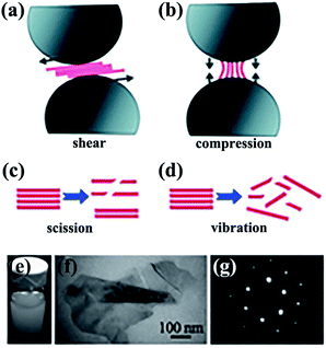 |
| | Fig. 1 Exfoliation of 2D nanosheets via low-energy ball milling caused by shear force (a) and compression force (b). Effects of sonication-induced scission (c) and vibration-induced exfoliation (d) on 2D nanosheets by sonication. (e) Dispersions of BNNSs in SDS–water. (f) Transmission electron microscope (TEM) image of folded BNNSs. (g) Selected area electron diffraction (SAED) observation of BNNSs from the right bottom area of (f). Reproduced with permission from ref. 26. | |
Liquid exfoliation of h-BN was successfully conducted in 1,2-dichloroethane solution of poly(m-phenyl-enevinylene-co-2,5-dictoxy-p-phenylenevinylene),29 water,30 SDS and water,31 N,N′-dimethylformamide (DMF),32 sulfonic acid, and methanesulfonic acid.33 To understand the functions of different solvents used in h-BN exfoliation, the Hansen solubility parameter (HSP) theory was proposed by Coleman et al.34 The exfoliation effect of the solvents could be verified by polar, hydrogen-bonding, cohesive energy density, which should minimize the energy of exfoliation or with strong, sufficient surface tension (e.g. γ 40 mJ m−2). With this theory, isopropyl alcohol (IPA) was a good exfoliation agent with a BNNS yield of ∼50% (0.06 mg mL−1 BNNS concentration). On the basis of this theory, analyzing the HSP distance and Ra value of diverse solvent mixtures, 55% ethanol and water solvent were better solvents than IPA that the dispersion concentration was 0.075 ± 0.003 mg mL−1.35 The effect of dispersion is presented in Fig. 2. Subsequently, ammonia solution and IPA were chosen as the exfoliation agents; ammonia molecules could intercalate the h-BN layers and thus benefited the exfoliation process.36 Given the large surface tension (γ = 33.3 mN m−1) and small HSP distance (Ra = 2.59 Å) of thionyl chloride, it could be potentially used to exfoliate and stabilize BNNS dispersions.37
 |
| | Fig. 2 (a) Photographs of BN dispersions in several ethanol/water mixtures stored under ambient conditions for 1 week. (b) BN suspensions in various ethanol/water mixtures and calculated Ra values are denoted by dots and solid lines, respectively. Reproduced with permission from ref. 35. | |
Epitaxial growth of monolayer h-BN was achieved on Pt (111) and Ru (001) substrates via adsorption and decomposition of borazine.38 Single-crystalline monolayer h-BN on the Ni (111) substrate with borazine as the precursor was prepared by Oshima et al.39 The Ni foil was considered as a preferred substrate because of the minor difference in the lattice constant between the Ni (111) surface (2.49 Å) and bulk h-BN (2.5 Å). Alternatively, B-trichloroborazine (ClBNH)3 was found to be a better precursor for monolayer h-BN growth on Pt (111)40 and Ni (111).41 BNNSs in the form of a so-called nanomesh were synthesized on a Rh (111) substrate by Corso et al.42 The types of substrate influenced the pore shapes and sizes of the nanomesh.43–48 A nanomesh could be grown on Ru (0001) and Rh (111). However, a flat monolayer h-BN could be grown on Pt (111), Cu (111), Fe (110), Pd (111), Cr (110), Mo (110), and Ni (111). Monolayer and nanomesh h-BN coexisted when Ir (111) was used as the substrate. Monolayer h-BN was grown on a four-inch Rh (111) substrate in a modified ultrahigh vacuum chamber.49 This h-BN surface exhibited a corrugated morphology. Similar patterns were observed on an epitaxial h-BN layer measuring 2 in. The wrinkle-free h-BN could be grown on a c-plane sapphire substrate measuring 2 in with the AA′ stacking order by modified low-pressure chemical vapor deposition (CVD).50
Cu and Ni foils were traditionally used as substrates for 2D h-BN growth because of their low-cost and excellent catalytic properties.51,52 Typical CVD processes for BNNS growth have used borazine and ammonia borane with Pt,53–55 Ni,56,57 and Cu58–63 as substrates. Wang et al.61 prepared a triangular monolayer single crystal h-BN measuring 20 μm. This size varied with the thermal annealing time of Cu foils (Fig. 3). Several catalyst-based substrates, such as heteroepitaxial Cu–Ni alloy,64 Co film,65 and Si-doped Fe substrate,66 have been explored. A study found that nanocrystalline graphene could be used as a seed layer for synthesizing large-area h-BN.67 In addition, h-BN could be grown on insulating substrates, such as SiO2/Si without a catalyst, via microwave plasma CVD.68 Few-layered BNNSs were grown by using a mixture of B, magnesium oxide (MgO), ferrous oxide (FeO) powders, and ammonia on silica (SiO2)/Si.69 Wafer-scale multilayer BNNSs were synthesized in vacuum with a subnanometer scale surface roughness.70
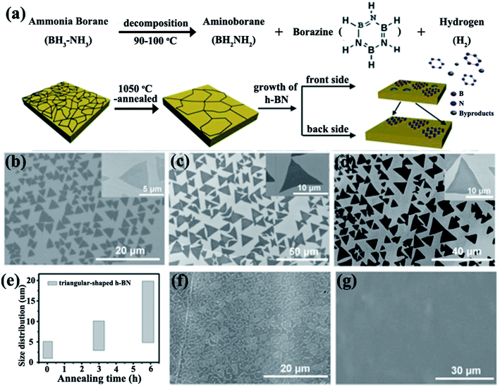 |
| | Fig. 3 (a) Dissociation of ammonia borate and h-BN growth. SEM images of h-BN grown without pre-annealing (b) and with annealing for 3 h (c) and 6 h (d). (e) Photograph showing variations in the domain size distributions of h-BN with the annealing time of Cu foils. SEM images of h-BN film formed by h-BN domains with growth times of about 65 min (f) and 70 min (g). Reproduced with permission from ref. 61. | |
3. Fabrication of h-BN-filled composites
The processing step exerts significant effects on the bulk properties of composites. Thus, methods of fabricating h-BN-filled composites are briefly reviewed, including solution mixing, melt blending, in situ polymerization, and ball milling.
3.1 Solution mixing
Solution mixing is a facile-operated, commonly used technique for fabricating h-BN-filled polymer composites. A suitable solvent is crucial for the uniform dispersion of h-BN and the polymer matrix, forming metastable suspensions of h-BN or h-BN/polymer mixtures. The critical technique during this process involves uniform stirring, which often requires the use of high-power ultrasonication.32 Some functionalized strategies, such as heat treatment,71 acid treatment72 or h-BN functionalization,73–75 were conducted to improve the dispersion of h-BN. Many h-BN/polymer composites were successfully prepared by solution mixing, including BN/polymethyl methacrylate (PMMA),32,76 BN/poly (vinyl alcohol) (PVA),74,77–79 BN/polybutylene terephthalate (PBT),80 BN/epoxy,75,81–83 BN/polyurethane acrylate (PUA),84 and BN/silicone rubber (SiR).14 Song et al.77 fabricated BNNS/PVA films by stirring the mixture of aqueous PVA solution and IPA suspension of BNNSs. The solvent was removed with vigorous stirring and then subjected to casting on an etched glass slide, resulting in a thin film with a thermal conductivity higher than 30 W m−1 K−1 (Fig. 4). However, solution mixing is limited to polymers that can be dissolved in solvents which are also suitable for the preparation of a stable suspension of h-BN.
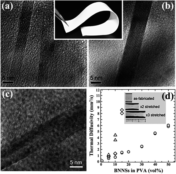 |
| | Fig. 4 (a and b) Cross-sectional TEM images of BNNSs/PVA (inset: photograph of a sample). (c) TEM image of BNNSs. (d) Thermal diffusivity of BNNS/PVA films with different BNNS contents. (○) represents the fabricated film, and (×2: ◊; and ×3: △) represents mechanically stretched films. Inset: photographs of as-fabricated and stretched films with 10 vol% BNNS. Reproduced with permission from ref. 77. | |
3.2 Melt blending
Melt blending is a solvent-free process suitable for industrial processes. This technique is usually applied to disperse sheets in a thermoplastic polymer matrix by using high-temperature and high-shear forces. h-BN/bisphenol E cyanate ester (BECy) nanocomposites were fabricated by preheating dopamine-treated h-BN nanoparticles at 130 °C and then mixing with a BECy resin, followed by curing at 180 °C and 250 °C (Fig. 5).73 However, melt blending was generally less effective in dispersing sheets in polymers, compared with solution mixing. This approach was limited to low filler loadings because of the high viscosity of the composites at high sheet loadings. Xie et al.85 subsequently prepared the mixture of BNNSs with poly(ethylene terephthalate) by melt processing. However, the BNNSs preferred to restack during the drying process. Thus, Guo et al.86 developed a slurry compounding strategy to fabricate BNNS/styrene–butadiene rubber (SBR) composites by using a conventional two-roll mill. The BNNS slurry was prepared using a solvent exchange route. Silane was added to strengthen the interfaces of BNNSs and SBR matrix. Compared with the neat SBR composites, the composites for 10.5 vol% Si–BNNS loading increased the thermal conductivity by 253%.
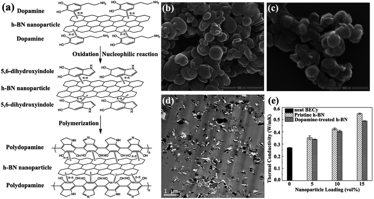 |
| | Fig. 5 (a) Illustration of polydopamine functionalized h-BN. SEM observations of h-BN (b) and dopamine-treated h-BN (c). (d) TEM image of h-BN/BECy composite with 15 vol% dopamine-treated h-BN. (e) Variations in the thermal conductivity of h-BN/BECy composite with nanoparticle loadings. Reproduced with permission from ref. 73. | |
3.3 In situ polymerization
Usually, a high filler loading would sacrifice the mechanical property of the composites. This could be ascribed to the poor stress transfer from matrix to filler caused by agglomeration of fillers. Thus, in situ polymerization was conducted to increase the interface bonding or adhesion between the fillers and polymer matrix. In situ polymerization involves dispersing the reactive monomer into sheet layers, followed by polymerization.87–90 This technique allows covalent bonding between functionalized sheets and the polymer matrix via chemical reaction. Distinct composites were prepared using this technique. Styrene was initiated on modified BNNSs by reversible addition–fragmentation chain transfer polymerization to prepare BNNS/polystyrene (PS) composites.87 Composites of h-BN/PMMA were fabricated by dispersing h-BN particles into methyl methacrylate monomers by bulk polymerization88 and atom transfer radical polymerization.89 A typical example was reported by Lee et al.90 in which poly(caprolactone) (PCL) was chemically grafted onto BNNSs by oxidized BNNSs (oxi-BNNSs) and subsequent ring-opening polymerization of PCL (Fig. 6). The resulting composites exhibited a thermal conductivity of 1.96 W m−1 K−1 with the incorporation of 20 wt% BNNSs.
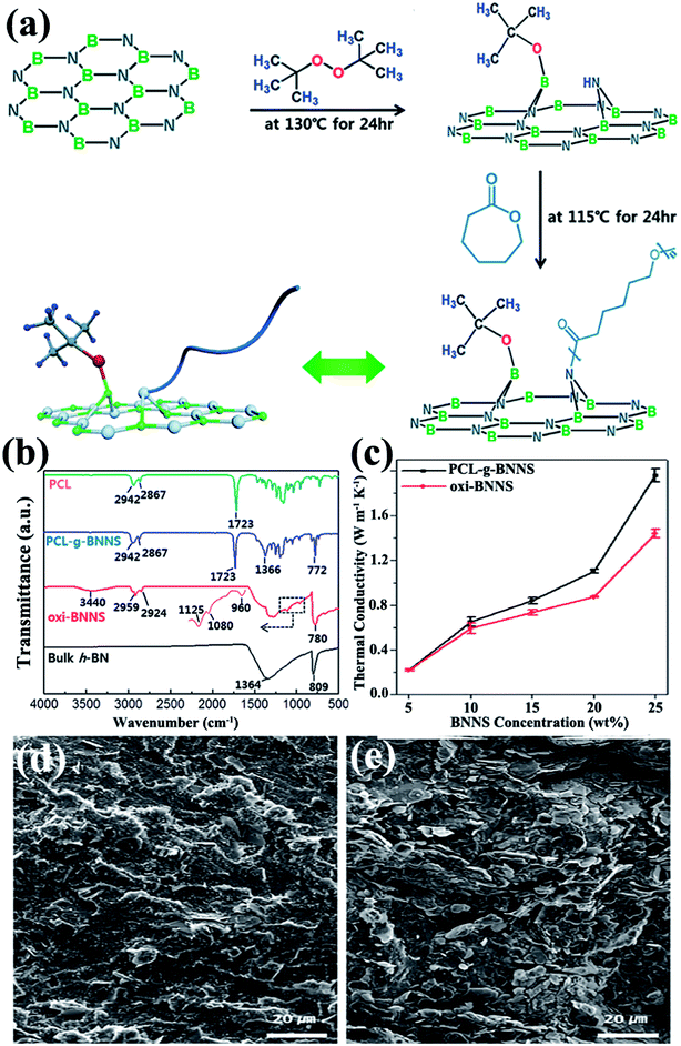 |
| | Fig. 6 (a) Fabrication of PCL–g-BNNSs. (b) IR spectra of PCL, PCL–g-BNNSs, oxi-BNNSs, and h-BN. (c) Thermal conductivity of oxi-BNNSs/PCL and PCL–g-BNNSs/PCL composites with BNNS contents. SEM observations of the cross-sectional images of PCL–g-BNNS/PCL (d) and oxi-BNNS/PCL (e) composites. Reproduced with permission from ref. 90. | |
3.4 Ball milling
Ball milling is a method of grinding materials into extremely fine powders or dispersions for practical application. The milling balls used are made of different materials, including stainless steel, ceramic, flint pebbles, and so on. High pressure is generated during milling because of the collision of tiny rigid balls in a concealed container. The behavior of powder particles upon milling is generally distinguished into mechanical milling, mechanical alloying, and mechanochemical synthesis. High-energy ball milling presents inherent advantages, such as low cost, versatility, and scalability. Therefore, high-energy ball milling is considered an industrialized technique for manufacturing materials in large quantities. Ball milling on layered materials generates strong shear and compression forces, which can peel off and cleave the materials (Fig. 1).26 Thus, ball milling is an excellent approach to reducing the thickness of h-BN. Lee et al.91 recently fabricated high-quality and high yield hydroxide BNNSs (OH–BNNSs) with high efficiency by hydroxide-assisted ball milling. The resulting OH–BNNSs showed little damage, relatively large sheets with an average size of 1.5 μm, and a high yield of 18%. Functionalized BNNSs (f-BNNSs) were used to fabricate polyethylene composites. Oxygen permeability was reduced by 46%, and water vapor permeability decreased by 34% with 5 wt% f-BNNS loading (Fig. 7). Various parameters, such as ball-to-powder ratios, milling speed, milling ball sizes, and milling agents, considered in the preparation of BNNSs in benzyl benzoate were systematically investigated by Chen et al.24 The obtained sample had a diameter ranging from 0.5 μm to 1.5 μm and a yield of 13.8%.
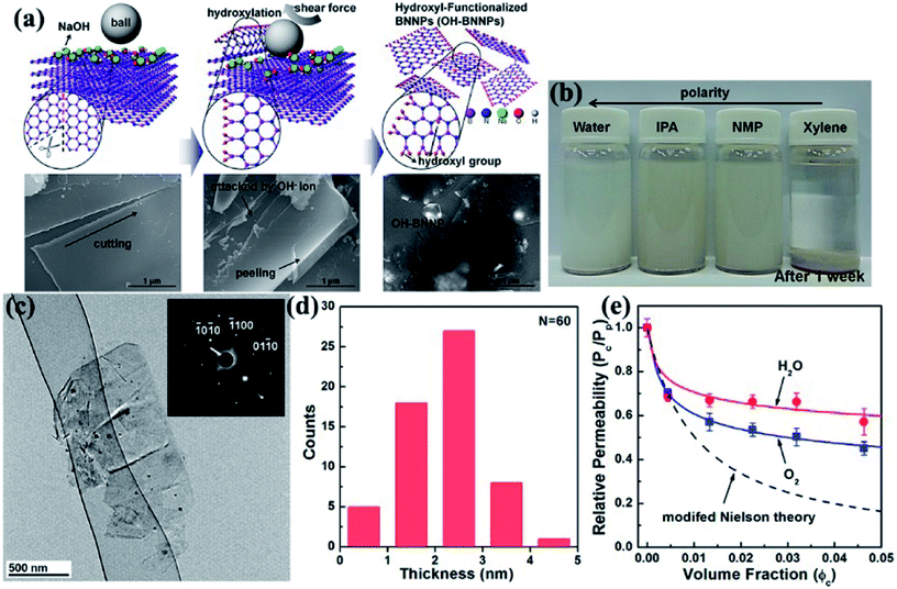 |
| | Fig. 7 (a) Schematic and corresponding SEM images of the exfoliation mechanism of h-BN. (b) Photographs of OH–BNNS suspensions in different solvents after sonication for 1 week. (c) TEM image of OH–BNNSs and corresponding SAED patterns. (d) Thickness of 60 platelets. (e) Permeabilities of oxygen and water vapor in composites with varying f-BNNS contents relative to that of the pristine polyethylene film, as well as the values calculated using the modified Nielsen theory. Reproduced with permission from ref. 91. | |
4. Conducting thermally conductive networks
The effective routes to assemble fillers in the polymer in order to construct well-organized and interconnected thermally conductive networks are critical for heat transfer. The usual strategies conducted for the construction of thermally conductive networks exhibit alignment, a three-dimensional (3D) network, an interface effect, a hybrid effect, and so on.
4.1 Alignment
h-BN is a platelet-shaped particle with a high aspect ratio. In one study, the thermal conductivity of h-BN reached 600 W m−1 K−1 in the in-plane direction and 30 W m−1 K−1 in the out-of-plane direction.12 Owing to the anisotropic shape and thermal conductivity of h-BN, the arrangement of h-BN in the polymer matrix considerably affected the thermal property of the h-BN-filled composites. Numerous reports recently evaluated the influence of orientation on thermal conductivity enhancement in a preferential direction. The methods used to orient h-BN included processing and external forces.
4.1.1 Alignment during processing. As shear force is introduced by processing methods, such as oscillatory shearing, tape casting, and injection molding, h-BN typically tends to align parallel to the planer direction, as in the case of h-BN oriented in PVA composite films by tape-casting.74 The thermal conductivity reached 5.4 W m−1 K−1 for 10 vol% filler contents. Ceramic particles were oriented in polyvinyl butyral and PVA matrices prepared using a similar method.92,93 Kuang et al.14 fabricated BNNS/SiR and BNNS/natural rubber (NR) composites with ultrahigh degree of orientation because of strong shear forces introduced by a two-roll mill (Fig. 8). The thermal conductivity of the composites was ∼4 W m−1 K−1 with 23 vol% BNNSs in SiR composites. h-BN/Polypropylene composites with a high degree of orientation were obtained by injection molding.94 The corresponding thermal conductivity showed a large increase, which reached 2.1 W m−1 K−1 with the incorporation of 40 vol% h-BN.
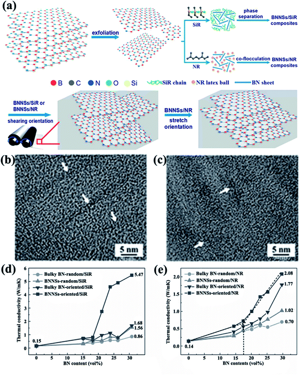 |
| | Fig. 8 (a) Preparation of BNNS/SiR and BNNS/NR composites. High-resolution TEM images of BNNS/SiR (b) and BNNS/NR (c) composites with 4 vol% BNNS loadings. Thermal conductivities of BNNS/SiR (d) and BNNS/NR (e) composites with different BNNS contents. Reproduced with permission from ref. 14. | |
4.1.2 Alignment by external fields. Alignment of h-BN in composites can be achieved by applying a suitable external field, such as magnetic, electric, and gravitational force fields.
4.1.2.1 Magnetic field alignment. Studart et al.95 proposed in 2012 an approach to align anisotropic reinforcing microparticles in the composite matrix by applying external magnetic fields. This proposal prompted a discussion among numerous researchers on thermal conductivity enhancement of h-BN-based composites by magnetic field-induced alignment. Reinforcing particles are often diamagnetic; as such, they were first coated with superparamagnetic nanoparticles. The filler arrangement in low-viscosity suspending fluids was controlled using a low external magnetic field. h-BN complex sheets modified with iron oxide nanoparticles were successfully rearranged in the direction vertical to the film plane in the study by Cho et al.,96 as shown in Fig. 9. Thus, iron oxide-coated h-BN filled epoxy composites exhibited excellent thermal properties.12,13,97 The highest thermal conductivity obtained was 4.7 W m−1 K−1 at 20 vol% iron oxide-coated h-BN for an epoxy resin system.13 Luo et al.98 used a similar method to fabricate iron oxide-coated h-BN/SiR composites. The thermal conductivity of the composites was 44.5% higher than that of the unaligned composites with 9.14 vol% filler loading. A theoretical model was used to analyze the results, suggesting that the orientation of the BNNSs mainly led to the improvement of thermal conductivity. CVD was also conducted to deposit iron oxide onto BNNSs. The obtained modified BNNSs were successfully oriented in the polysiloxane matrix with a magnetic field (Fig. 9).96
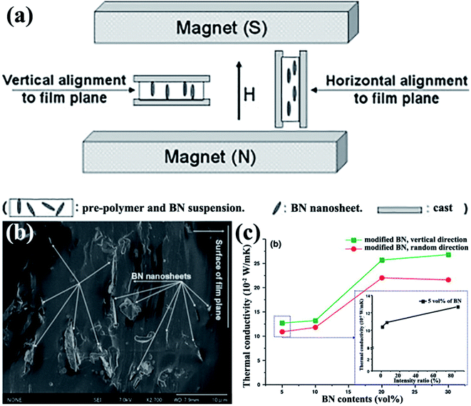 |
| | Fig. 9 (a) Illustration of experimental setups. (b) Fracture images of polysiloxane composites at 5 vol% BN loading with horizontal alignment. (c) Variations in the thermal conductivity of BNNS/polysiloxane composite films with BNNS loadings (inset: variations in the thermal conductivity of composites with 5 vol% BN content as a function of intensity ratio). Reproduced with permission from ref. 96. | |
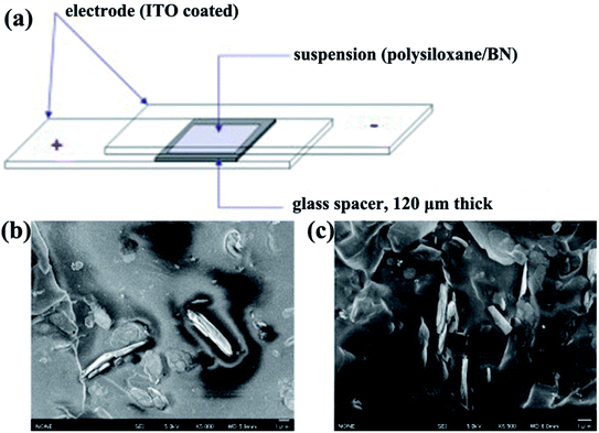 |
| | Fig. 10 (a) Illustration of the experimental setup for the fabrication of aligned BN/polymer films. Cross-sectional SEM micrographs of an oriented BN/polysiloxane composite at 10 vol% BN content without (b) and with (c) the application of electric fields. Reproduced with permission from ref. 99. | |
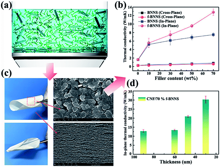 |
| | Fig. 11 (a) Demonstration of BNNSs or f-BNNSs in CNF aqueous solution during vacuum-assisted filtration. (b) Thermal conductivity of CNF composite films. (c) Photographs of CNF/BNNS and CNF/f-BNNS films with 70 wt% BNNS loadings and the corresponding SEM images. (d) In-plane thermal conductivity of CNF/f-BNNS films at 70 wt% filler contents with different thicknesses. Reproduced with permission from ref. 102. | |
4.2 3D networks
Isotropic thermally conductive bulk composites are favorable to a certain extent in some applications. Thus, forming three-dimensional (3D) networks with high quality and low thermal resistance for heat conduction present a significant challenge. Up to now, the commonly strategy used to construct 3D networks was to form thermally conductive networks firstly and then infiltrating with polymer. Thus, the thermal performance of the composites improved a lot at only a low filler loading. The thermal conductivity enhancement efficiency of 3D network composites to pure polymer matrix was expressed by thermal conductivity enhancement per 1 vol% loading (η),105 which was defined as η = (K − Km) × 100%/(100 × VKm), where K and Km represented the thermal conductivity of the composites and polymer matrix, respectively. And V represented the volume contents of h-BN in composites. As shown in Fig. 12, CNF-supported 3D-interconnected BNNS (3D-C-BNNS) aerogels were fabricated by self-assembly of BNNSs on a 3D cellulose skeleton via sol–gel and freeze-drying.106 Composites exhibiting high thermal conductivity were then prepared by impregnating epoxy resin into the 3D BNNS aerogel. Ultrahigh thermal conductivity of 3.13 W m−1 K−1 was achieved at a low BNNS loading level of 9.6 vol%, which corresponded to a thermal conductivity enhancement of about 1400%. In addition, the thermal conductivity enhancement could be easily adjusted by tailoring the BNNS loadings in the interconnected 3D network.
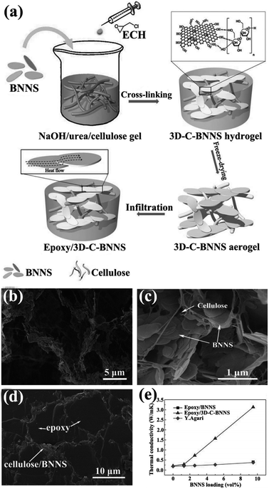 |
| | Fig. 12 (a) Preparation of epoxy/3D-C-BNNS composites. SEM views of 3D-C-BNNS aerogel with 5 vol% (b) and 9.6 vol% (c) BNNSs. (d) SEM image of the cross-sectional structure of epoxy/3D-C-BNNS composites with 9.6 vol% BNNS loading. (e) Thermal conductivity of composite variations with BNNS loadings. Reproduced with permission from ref. 106. | |
An ice-templated approach was reported to construct 3D BNNS networks (Fig. 13).105 This strategy obtained epoxy composites with high thermal conductivity (2.85 W m−1 K−1) at a relatively low filler content (9.29 vol%). Yang et al.107 subsequently used a similar method to fabricate graphene oxide (GO)/h-BN hybrid porous scaffolds by introducing polyethylene glycol and obtained thermal conductivity of 1.84 W m−1 K−1 at 19.2 wt% h-BN.
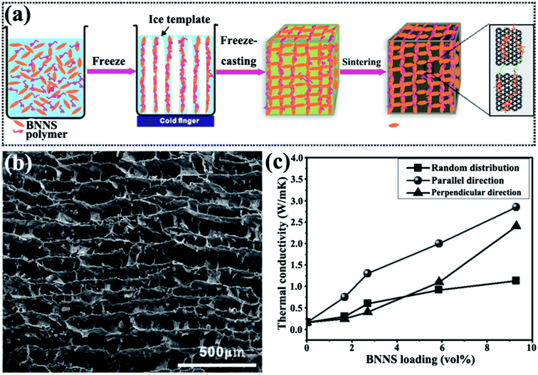 |
| | Fig. 13 (a) Preparation of 3D-BNNS/epoxy composites. (b) SEM image of 3D-BNNS aerogel with a density of 195.2 mg cm−3 in the vertical direction to ice growth. (c) Thermal conductivity of composite variations with BNNS loadings. Reproduced with permission from ref. 105. | |
4.3 Interface effect
A large body of evidence supports the finding that surface modification can reduce interface thermal resistance. For chemical surface modification, covalent bonding or noncovalent bonding are the commonly used methods to connect the polymer matrix and fillers.
4.3.1 Covalent modification. Covalent functionalization of BNNSs requires the formation of covalent bonds on the basal plane of the BNNS lattice. Attributed to the partial ionic characteristic of B–N bonds in an h-BN structure, its B atom bore a partially positive charge, whereas the N atom bore a negative charge. This characteristic exposed B and N sites to attacks by nucleophilic and electrophilic groups, respectively.Several studies have thus far been reported on the production of OH–BNNSs and subsequent OH–BNNSs/polymer composites with enhanced thermal performance. In 2013, 30% hydrogen peroxide was used to treat h-BN powders in an autoclave at 100 °C.108 The functionalization of h-BN was found to have improved the compatibility among fillers and the matrix, resulting in a high thermal conductivity of 3.92 W m−1 K−1 at 10 wt% h-BN loadings in the PVA matrix. Tang et al.109 employed a mixed solution of concentrated sulfuric acid (H2SO4) and nitric acid (HNO3) to synthesize acid-treated BNNSs to enhance the thermal performance of epoxy composites. Thus, the thermal conductivity channel of the obtained composites was first constructed at 5.05 wt%, which was higher than that of pure BNNS-epoxy composites at 6.10 wt%. These methods were based on a liquid medium, which was difficult to remove completely because of their high boiling points. Therefore, a 1-step route in the preparation of OH–BNNS was developed by Huang et al.71 by which h-BN could be directly exfoliated at a high temperature of 850 °C (Fig. 14). The resulting OH–BNNSs exhibited excellent dispersibility in water (concentration of 0.3 mg mL−1) and ethanol (concentration of 0.06 mg mL−1), rendering the OH–BNNSs effective as a hydrogel additive. The OH–BNNS/poly(N-isopropylacrylamide) (PNIPAM) hydrogel composite showed a 41% increase in thermal conductivity at 0.07 wt% OH–BNNS. In addition, Xu et al.72 treated h-BN with acetone, HNO3, H2SO4, and silane, showing varying levels of effectiveness in enhancing thermal conductivity. The results exhibited that surface treatment using silane Z-6040 (2.4%) was most effective for h-BN. The thermal conductivity reached 10.3 W m−1 K−1 at 57 vol% h-BN loading. The introduced –OH groups improved the interface compatibility; thus, the diffuse path of phonon was opened between BNNSs and the polymer matrix, leading to increased thermal conductivity.
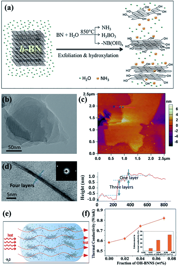 |
| | Fig. 14 (a) Exfoliation and hydroxylation of h-BN. (b) TEM image showing a Moiré patterns. (c) AFM observation showing OH–BNNSs and corresponding height profiles. (d) TEM image showing few-layered OH–BNNSs and the corresponding SAED. (e) Heat transfer in OH–BNNS/PNIPAM hydrogel. (f) Thermal conductivity variations of hydrogels with OH–BNNS (inset: percentages of thermal enhancement). Reproduced with permission from ref. 71. | |
The OH–BN or NH2–BN typically served as the initiators in the design of many complex h-BN derivatives. The obtained h-BN derivatives were used as fillers to enhance the interface adhesion between h-BN and the polymer matrix, leading to a higher dispersion of platelets in polymers and enhancing the thermal performance. To enhance the affinity of the BNNS/polymer interface, a hyperbranched polyamide (HBP) was attached to the modified BNNSs. The HBP was formed by introducing amino groups to the surface of BNNSs and then initiating HBP growth (Fig. 15).75,82 The obtained epoxy composites exhibited a thermal conductivity of 9.81 W m−1 K−1 with 50 vol% BNNSs. Kim et al.81,84,110 conducted studies on grafting silane coupling agents onto the h-BN surface for a high thermal performance. The common strategy was to attach a hydroxyl group onto the h-BN surface by using sodium hydroxide at a high temperature, followed by grafting silane coupling agents, such as 3-(glycidoxypropyl)trimethoxysilane, 3-chloropropyltrimethoxysilane,81,110 and 3-aminopropyltriethoxy silane,84 to modify the surfaces, which was a smart route to reduce interface thermal resistance. The chemical reagents used in these strategies were not environmentally friendly, and solvent removal entailed difficulty. Consequently, a solvent-free method was developed by Zhi et al.111 to fabricate epoxy composites. The h-BN powder was treated with KH550, a silane coupling agent, followed by mixing with a solid-state epoxy resin. This strategy was suitable for nearly any filler fraction. The maximum thermal conductivity reached 5.24 W m−1 K−1.
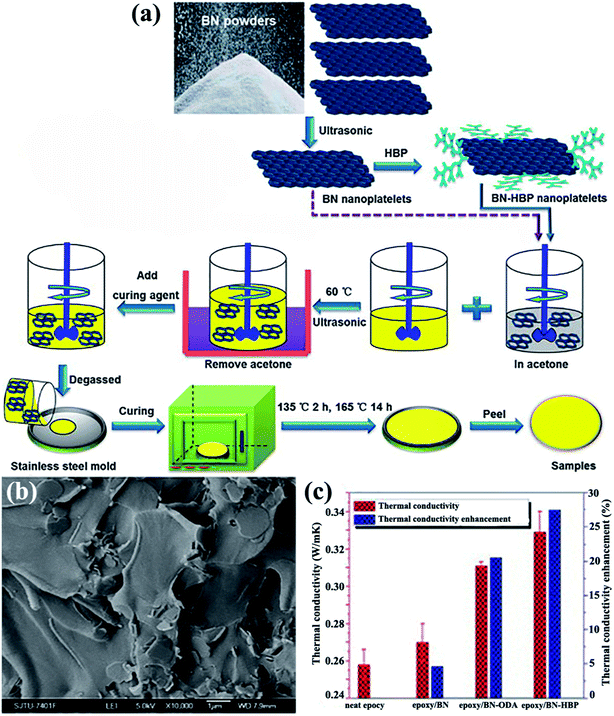 |
| | Fig. 15 (a) Preparation of the epoxy composites. (b) Cross-sectional SEM image of the epoxy/BN-HBP composite surface. (c) Thermal conductivity and the corresponding enhancements of the composites at 100 °C. Reproduced with permission from ref. 75. | |
4.3.2 Noncovalent modification. Noncovalent bonding is a facile method to modify the surface without introducing defects on the surface of BNNSs. Noncovalent modification was the technique employed to physically adsorb polymer on the surface of BNNSs. Thus, the crystallinity of noncovalent functionalized BNNSs was perfectly maintained even after treatment while interfacial adhesion between BNNSs and the matrix increased. Therefore, the thermal conductivity of the composites was enhanced.Owing to its superior adhesive ability, polydopamine (PDA) was typically applied to modify the surface of h-BN. Xu et al.74 adopted dopamine chemistry to coat a thickness of about 4 nm PDA on the h-BN surface (Fig. 16). The thermal conductivity of h-BN@PDA/PVA composites was about 5.4 W m−1 K−1 with the addition of 10 vol% h-BN@PDA. Meanwhile, Kessler et al.73 used a similar method to prepare h-BN@PDA/BECy composites and achieved a lower thermal performance of 0.5 W m−1 K−1 for a 15 vol% filler loading. In addition, chlorosulfonic acid (CSA) exhibited strong physical adsorption on h-BN surfaces.80 The physical adsorption of CSA provided high solubility for BNNSs in various organic solvents and thermoplastic polymers, yielding NF-BNNS/PBT composite films with enhanced through-plane thermal conductivity of up to 11.0 W m−1 K−1.
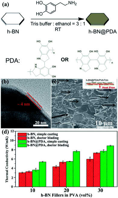 |
| | Fig. 16 (a) Process of dopamine chemistry. (b) TEM image of h-BN@PDA microplatelets. (c) Fracture SEM image of the h-BN@PDA composite film with 20 vol% h-BN contents prepared by doctor blading. (d) Thermal conductivity of the fabricated composite films. Reproduced with permission from ref. 74. | |
4.4 Hybrid effect
The simultaneous use of fillers with different shapes and types was an alternative strategy to enhance the thermal performance of composites.
4.4.1 Morphology and size effect. The effects of 11 artificially designed filler shapes on the thermal conductivity of the composite materials were evaluated.112 The results indicated that the best fillers have long heat transfer distances and continuously large contact areas. Double Y-shaped fillers were considered preferable to other fillers, whereas spherical fillers were considered the worst. In addition to shape, hybrid sizes can influence thermal performance because large h-BN has a longer heat transfer distance than that of small h-BN. The large h-BN contributed more to the thermal conductivity of the material. The small h-BN could bridge the distances between h-BN crystals to increase contact.113,114 Hybrid h-BN with M0.3 μm![[thin space (1/6-em)]](https://www.rsc.org/images/entities/char_2009.gif) :
:![[thin space (1/6-em)]](https://www.rsc.org/images/entities/char_2009.gif) M6 μm
M6 μm![[thin space (1/6-em)]](https://www.rsc.org/images/entities/char_2009.gif) :
:![[thin space (1/6-em)]](https://www.rsc.org/images/entities/char_2009.gif) M20 μm at a mass ratio of 1
M20 μm at a mass ratio of 1![[thin space (1/6-em)]](https://www.rsc.org/images/entities/char_2009.gif) :
:![[thin space (1/6-em)]](https://www.rsc.org/images/entities/char_2009.gif) 1
1![[thin space (1/6-em)]](https://www.rsc.org/images/entities/char_2009.gif) :
:![[thin space (1/6-em)]](https://www.rsc.org/images/entities/char_2009.gif) 2 in a total of 40 vol% leads to a higher thermal conductivity of 1.482 W m−1 K−1 in SiR composites than that of 50 vol% BN6 μm with a thermal conductivity of 1 W m−1 K−1.115 Subsequently, microsized and nanosized BN were combined to prepare polyimide (PI) films.116 The obtained sample filled with 30 wt% h-BN (microsize
2 in a total of 40 vol% leads to a higher thermal conductivity of 1.482 W m−1 K−1 in SiR composites than that of 50 vol% BN6 μm with a thermal conductivity of 1 W m−1 K−1.115 Subsequently, microsized and nanosized BN were combined to prepare polyimide (PI) films.116 The obtained sample filled with 30 wt% h-BN (microsize![[thin space (1/6-em)]](https://www.rsc.org/images/entities/char_2009.gif) :
:![[thin space (1/6-em)]](https://www.rsc.org/images/entities/char_2009.gif) nanosized = 7
nanosized = 7![[thin space (1/6-em)]](https://www.rsc.org/images/entities/char_2009.gif) :
:![[thin space (1/6-em)]](https://www.rsc.org/images/entities/char_2009.gif) 3 wt%) obtained a thermal conductivity of up to 1.2 W m−1 K−1. This value was higher than that obtained using pure microsized BN. These enhancements in thermal property were attributed to the high packing density and ease of formation of heat transfer pathways. The studies mainly discussed the effects exerted by microsized BN, whereas those by nanosized BN were rarely reported. Thus, Kemaloglu et al.117 used 3 micro-size and 2 nanosized h-BN with different particle sizes and shapes in SiR composites. The results showed that nanosized BN could not promote the thermal conductivity as much as the microsize BN. A plate-like particle with an aspect ratio of 20 was believed to exhibit the highest thermal performance.
3 wt%) obtained a thermal conductivity of up to 1.2 W m−1 K−1. This value was higher than that obtained using pure microsized BN. These enhancements in thermal property were attributed to the high packing density and ease of formation of heat transfer pathways. The studies mainly discussed the effects exerted by microsized BN, whereas those by nanosized BN were rarely reported. Thus, Kemaloglu et al.117 used 3 micro-size and 2 nanosized h-BN with different particle sizes and shapes in SiR composites. The results showed that nanosized BN could not promote the thermal conductivity as much as the microsize BN. A plate-like particle with an aspect ratio of 20 was believed to exhibit the highest thermal performance.
4.4.2 h-BN/nanoparticle-filled composites. Interfacial thermal resistance is regarded as the main factor influencing the thermal performance of composites, which arises from poor mechanical or chemical adherence at interfaces. The aforementioned strategies were related to the reduction in filler/matrix resistance. However, studies on the filler/filler interface have rarely been reported. Jiang et al.118 used α-alumina (α-Al2O3) to bridge BNNSs to construct more compactible 3D thermally conductive networks, resulting in more heat transfer pathways in the composites. The obtained sample exhibited a thermal conductivity of 0.808 W m−1 K−1 at 26.5 vol% filler loading. Permal et al.119 recently combined polygonal Al2O3 and BN to improve the thermal performance of epoxy composites, which reached 0.57 W m−1 K−1 with the addition of a 30 wt% filler (Al2O3![[thin space (1/6-em)]](https://www.rsc.org/images/entities/char_2009.gif) :
:![[thin space (1/6-em)]](https://www.rsc.org/images/entities/char_2009.gif) BN1 μm = 5
BN1 μm = 5![[thin space (1/6-em)]](https://www.rsc.org/images/entities/char_2009.gif) :
:![[thin space (1/6-em)]](https://www.rsc.org/images/entities/char_2009.gif) 5). Layer-shaped fillers were more favorable than the ball-shaped or sharp-corner-shaped fillers in improving the thermal performance of epoxy resins.120 However, the thermal conductivity remained low because of the absence of contact between Al2O3 and BNNSs. Silver nanoparticles (AgNPs) could be sintered together during epoxy curing and acted as “solders” to link BNNSs. AgNP-deposited BNNSs (BNNSs/AgNPs) were used as fillers for the epoxy matrix and provided a higher thermal conductivity of 3.06 W m−1 K−1 with 25.1 vol% BNNS loading.121 However, the obtained thermal conductivity remained lower than 5 W m−1 K−1. Thus, silicon carbide nanowires (SiCNWs) were introduced to enhance the thermal performance of PVA composites.122 Bioinspired BNNS–AgNP/SiCNW–AgNP/PVA composite papers were fabricated and exhibited a superior thermal conductivity of about 21.7 W m−1 K−1. The preparation process is illustrated in Fig. 17.
5). Layer-shaped fillers were more favorable than the ball-shaped or sharp-corner-shaped fillers in improving the thermal performance of epoxy resins.120 However, the thermal conductivity remained low because of the absence of contact between Al2O3 and BNNSs. Silver nanoparticles (AgNPs) could be sintered together during epoxy curing and acted as “solders” to link BNNSs. AgNP-deposited BNNSs (BNNSs/AgNPs) were used as fillers for the epoxy matrix and provided a higher thermal conductivity of 3.06 W m−1 K−1 with 25.1 vol% BNNS loading.121 However, the obtained thermal conductivity remained lower than 5 W m−1 K−1. Thus, silicon carbide nanowires (SiCNWs) were introduced to enhance the thermal performance of PVA composites.122 Bioinspired BNNS–AgNP/SiCNW–AgNP/PVA composite papers were fabricated and exhibited a superior thermal conductivity of about 21.7 W m−1 K−1. The preparation process is illustrated in Fig. 17.
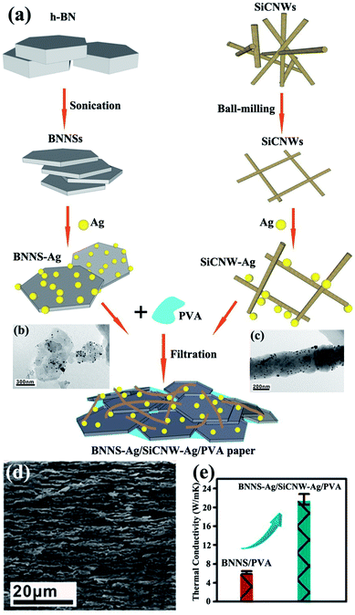 |
| | Fig. 17 (a) Fabrication of BNNS–Ag/SiCNW–Ag/PVA paper. TEM images of BNNS–Ag (b) and SiCNW–Ag (c). (d) Fracture SEM observation of BNNS–Ag/SiCNW–Ag/PVA paper. (e) Thermal conductivity of BNNS/PVA and BNNS–Ag/SiCNW–Ag/PVA papers. Reproduced with permission from ref. 122. | |
4.4.3 h-BN/carbon material-filled composite. To enhance the affinity between fillers and the polymer matrix, the common route was to modify the surface of the fillers. Carbon materials, such as graphene and carbon nanotubes (CNTs), and h-BN were combined as a mixed filler to improve the thermal performance of the polymer matrix. The mixed fillers were found to exert a synergistic effect on the thermal enhancement of the composites. When coupling agent-functionalized BN (f-BN) was combined with glycidyl methacrylate-grafted graphene (g-TrG) and then added into the PI matrix, the voids between BN and the PI matrix were filled by the graphene nanolayers.123 The process is illustrated in Fig. 18. The resulting composites containing additional 1 wt% g-TrG exhibited a thermal conductivity of 2.11 W m−1 K−1, which was at least doubled to the value of f-BN/PI. The graphene content in the mixed fillers was smaller. Meanwhile, when the BN content was smaller, the nanosized BN was filled into the graphene interspaces and thus formed a BN/graphene stacked structure, markedly enhancing the thermal conductivity.124 Additional 1.5 wt% h-BN could increase the thermal conductivity to 38% and 34% in PS and polyamide 6 (PA 6) matrix, respectively. The previously described fillers were based on 2D platelets. Once the 1D and 2D fillers were mixed, a hybrid 3D filler network structure could be formed. Thus, a small amount of CNTs (2 wt%) was introduced into the BN-filled poly(vinylidene fluoride) (PVDF) composites.125 The results showed that the addition of CNTs to the BN/PVDF composites facilitated the formation of a denser 3D BN/CNT network structure. The thermal conductivity of 1.3 W m−1 K−1 at 22 wt% filler loading (2 wt% CNTs and 20 wt% BN) was thus enhanced. This thermal conductivity was higher than that of PVDF/20 wt% BN (0.97 W m−1 K−1) and PVDF/2 wt% CNTs (0.28 W m−1 K−1).
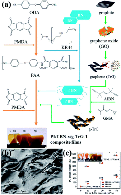 |
| | Fig. 18 (a) Preparation of fillers (f-BN and g-TrG) and composite films (PI/f-BN-x/g-TrG-1). (b) SEM observation of the fractured surface of PI/f-BN-30/g-TrG-1. (c) Variations in thermal conductivity with BN or f-BN contents. Reproduced with permission from ref. 123. | |
5. Summary and outlook
In the current study, the fabrication methods of BNNSs and h-BN-filled composites, as well as the construction of thermally conductive networks, were summarized based on the most updated research. Studies on BNNS-filled thermally conductive polymer composites remained at their early stage for several reasons. First, the preparation of BNNSs on a large scale was difficult for a strong “lip–lip” interaction between B–N bonds on the BNNS plane that was difficult to exfoliate. Several techniques, such as mechanical and liquid exfoliation, CVD, and epitaxy, were conducted to fabricate 2D h-BN with configurations and variations in quality. Liquid exfoliation by sonicating bulk h-BN in suitable solvents would lead to a high yield. However, the lateral size of BNNS obtained by this method was usually smaller than other methods, such as CVD. Thus, it was desirable to develop effective strategies to prepare BNNS with large lateral size. The sample obtained by CVD growth could provide a high quality. However, the high temperature requirement and the transfer process, as well as the use of catalytic substrates, could be the main restrictions for the production of highly crystalline h-BN and construction of high-performance devices. Second, the properties of the interface and dispersion exerted important effects on the composite materials. The BN nanostructure was difficult to disperse uniformly in the polymer matrix due to its inert surface. Generally, the universal method used to improve the interface between BNNSs and the polymer matrix was surface modification. The common groups were identified as the hydroxyl group and the amino group. The hydroxyl group was connected to the B site, whereas the amino group was hydrogenated at the N site. Surface modification of h-BN was an optimal method to decrease the interface thermal resistance among the fillers and the matrix, as well as to promote good dispersion. In addition, since ball milling was based on mechanochemistry, it was found to be a good protocol to improve the interface and dispersion between fillers and matrix. However, this inevitably sacrificed the crystallinity of the fillers due to the intense shear force introduced by the ball milling process. Thus, it was desirable to develop an effective method to promote the dispersion of fillers in the matrix as well as maintain the quality of the fillers. Third, the strategies for constructing thermally conductive pathways have rarely been reported. Owing to the anisotropic thermal performance of 2D h-BN, the orientation preferred to prepare a composite with a high thermal conductivity in a special direction. 3D networks in perpendicular and parallel directions could lead to a high thermal conductivity. However, the strategies for constructing orientation or 3D networks remained limited. In addition, mixing hybrid fillers was a significant method used to form and improve heat conduction. However, the interface between nanoparticles and BNNS has great influence on the heat transfer in the hybrids. Therefore, the synergistic effect between BNNS and other functional materials, especially different polymers and various nanoparticles, remained to be exploited in the near future.
Conflicts of interest
There are no conflicts of interest to declare.
Acknowledgements
This work was supported by the National Natural Science Foundation of China (No. 51522211, 51602339 and 51703241), the Key Research Program of Frontier Science of Chinese Academy of Sciences (No. QYZDB-SSW-SLH031), the Thousand Youth Talents Plan, the Postdoctoral Foundation of China (No. 2016M601905 and 2017M621855), the Natural Science Foundation of Jiangsu Province, China (No. BK20160399), the Postdoctoral Foundation of Jiangsu Province (No. 1601065B), and the Science and Technology Project of Suzhou, China (No. SZS201508).
References
- D. Lu and C. P. Wong, Materials for advanced packaging, Springer, New York, 2009 Search PubMed.
- C. P. Wong, K. S. Moon and Y. Li, Nano-bio-electronic, photonic and MEMS packaging, Springer, New York, 2010 Search PubMed.
- A. L. Moore and L. Shi, Mater. Today, 2014, 17, 163–174 CrossRef.
- Y. X. Wang, N. Xu, D. Y. Li and J. Zhu, Adv. Funct. Mater., 2017, 27, 1604134 CrossRef.
- A. A. Balandin, S. Ghosh, W. Z. Bao, I. Calizo, D. Teweldebrhan, F. Miao and C. N. Lau, Nano Lett., 2008, 8, 902–907 CrossRef PubMed.
- H. S. Kim, J. H. Kim, W. Y. Kim, H. S. Lee, S. Y. Kim and M. S. Khil, Carbon, 2017, 119, 40–46 CrossRef.
- Z. Luo, J. Maassen, Y. X. Deng, Y. C. Du, R. P. Garrelts, M. S. Lundstrom, P. D. Ye and X. F. Xu, Nat. Commun., 2015, 6, 8572 CrossRef PubMed.
- C. R. Dean, A. F. Young, I. Meric, C. Lee, L. Wang, S. Sorgenfrei, K. Watanabe, T. Taniguchi, P. Kim, K. L. Shepard and J. Hone, Nat. Nanotechnol., 2010, 5, 722–726 CrossRef PubMed.
- C. Zhi, Y. Bando, T. Terao, C. Tang, H. Kuwahara and D. Golberg, Adv. Funct. Mater., 2009, 19, 1857–1862 CrossRef.
- K. C. Yung and H. Liem, J. Appl. Polym. Sci., 2007, 106, 3587–3591 CrossRef.
- Y. Xu and D. D. L. Chung, Compos. Interfaces, 2000, 7, 243–256 CrossRef.
- Z. Lin, Y. Liu, S. Raghavan, K. S. Moon, S. K. Sitaraman and C. P. Wong, ACS Appl. Mater. Interfaces, 2013, 5, 7633–7640 CrossRef PubMed.
- H. S. Lim, J. W. Oh, S. Y. Kim, M. J. Yoo, S. D. Park and W. S. Lee, Chem. Mater., 2013, 25, 3315–3319 CrossRef.
- Z. Kuang, Y. Chen, Y. Lu, L. Liu, S. Hu, S. Wen, Y. Mao and L. Zhang, Small, 2015, 11, 1655–1659 CrossRef PubMed.
- D. Golberg, Y. Bando, Y. Huang, T. Terao, M. Mitome, C. Tang and C. Zhi, ACS Nano, 2010, 4, 2979–2993 CrossRef PubMed.
- G. R. Bhimanapati, N. R. Glavin and J. A. Robinson, Semicond. Semimetals, 2016, 95, 101–147 Search PubMed.
- W. L. Song, P. Wang, L. Cao, A. Anderson, M. J. Meziani, A. J. Farr and Y. P. Sun, Angew. Chem., Int. Ed., 2012, 51, 6498–6501 CrossRef PubMed.
- L. Boldrin, F. Scarpa, R. Chowdhury and S. Adhikari, Nanotechnology, 2011, 22, 505702 CrossRef PubMed.
- K. Rajesh, G. Rajasekaran and P. Avinash, Nanotechnology, 2016, 27, 085706 CrossRef PubMed.
- J. C. Meyer, A. Chuvilin, G. Algara-Siller, J. Biskupek and U. Kaiser, Nano Lett., 2009, 9, 2683–2689 CrossRef PubMed.
- R. V. Gorbachev, I. Riaz, R. R. Nair, R. Jalil, L. Britnell, B. D. Belle, E. W. Hill, K. S. Novoselov, K. Watanabe, T. Taniguchi, A. K. Geim and P. Blake, Small, 2011, 7, 465–468 CrossRef PubMed.
- D. Pacilé, J. C. Meyer, Ç. Ö. Girit and A. Zettl, Appl. Phys. Lett., 2008, 92, 133107 CrossRef.
- L. H. Li, Y. Chen, G. Behan, H. Zhang, M. Petravic and A. M. Glushenkov, J. Mater. Chem., 2011, 21, 11862 RSC.
- Deepika, L. H. Li, A. M. Glushenkov, S. K. Hait, P. Hodgson and Y. Chen, Sci. Rep., 2014, 4, 7288 CrossRef PubMed.
- D. Fan, J. Feng, J. Liu, T. Gao, Z. Ye, M. Chen and X. Lv, Ceram. Int., 2016, 42, 7155–7163 CrossRef.
- Y. Yao, Z. Lin, Z. Li, X. Song, K. S. Moon and C. P. Wong, J. Mater. Chem., 2012, 22, 13494 RSC.
- Z. Lin, A. McNamara, Y. Liu, K. S. Moon and C. P. Wong, Compos. Sci. Technol., 2014, 90, 123–128 CrossRef.
- L. Lin, X. Zhitao, H. Daqiang, W. Guotao, L. Bin and C. Ping, Chem. Lett., 2013, 42, 1415–1416 CrossRef.
- W. Q. Han, L. Wu, Y. Zhu, K. Watanabe and T. Taniguchi, Appl. Phys. Lett., 2008, 93, 223103 CrossRef.
- Y. Lin, T. V. Williams, T. B. Xu, W. Cao, H. E. Elsayed-Ali and J. W. Connell, J. Phys. Chem. C, 2011, 115, 2679–2685 CrossRef.
- R. J. Smith, P. J. King, M. Lotya, C. Wirtz, U. Khan, S. De, A. O'Neill, G. S. Duesberg, J. C. Grunlan, G. Moriarty, J. Chen, J. Wang, A. I. Minett, V. Nicolosi and J. N. Coleman, Adv. Mater., 2011, 23, 3944–3948 CrossRef PubMed.
- C. Zhi, Y. Bando, C. Tang, H. Kuwahara and D. Golberg, Adv. Mater., 2009, 21, 2889–2893 CrossRef.
- Y. Wang, Z. Shi and J. Yin, J. Mater. Chem., 2011, 21, 11371–11377 RSC.
- J. N. Coleman, M. Lotya, A. O'Neill, S. D. Bergin, P. J. King, U. Khan, K. Young, A. Gaucher, S. De, R. J. Smith, I. V. Shvets, S. K. Arora, G. Stanton, H. Y. Kim, K. Lee, G. T. Kim, G. S. Duesberg, T. Hallam, J. J. Boland, J. J. Wang, J. F. Donegan, J. C. Grunlan, G. Moriarty, A. Shmeliov, R. J. Nicholls, J. M. Perkins, E. M. Grieveson, K. Theuwissen, D. W. McComb, P. D. Nellist and V. Nicolosi, Science, 2011, 331, 568–571 CrossRef PubMed.
- K. G. Zhou, N. N. Mao, H. X. Wang, Y. Peng and H. L. Zhang, Angew. Chem., Int. Ed., 2011, 50, 10839–10842 CrossRef PubMed.
- L. Cao, S. Emami and K. Lafdi, Mater. Express, 2014, 4, 165–171 CrossRef.
- H. B. Cho, T. Nakayama, H. Suematsu, T. Suzuki, W. Jiang, K. Niihara, E. Song, N. S. A. Eom, S. Kim and Y. H. Choa, Compos. Sci. Technol., 2016, 129, 205–213 CrossRef.
- M. T. Paffett, R. J. Simonson, P. Papin and R. T. Paine, Surf. Sci., 1990, 232, 286–296 CrossRef.
- A. Nagashima, N. Tejima, Y. Gamou, T. Kawai and C. Oshima, Phys. Rev. B, 1995, 51, 4606–4613 CrossRef.
- F. Müller, K. Stöwe and H. Sachdev, Chem. Mater., 2005, 17, 3464–3467 CrossRef.
- W. Auwärter, H. U. Suter, H. Sachdev and T. Greber, Chem. Mater., 2004, 16, 343–345 CrossRef.
- M. Corso, W. Auwärter, M. Muntwiler, A. Tamai, T. Greber and J. Osterwalder, Science, 2004, 303, 217–220 CrossRef PubMed.
- N. A. Vinogradov, A. A. Zakharov, M. L. Ng, A. Mikkelsen, E. Lundgren, N. Mårtensson and A. B. Preobrajenski, Langmuir, 2012, 28, 1775–1781 CrossRef PubMed.
- F. Müller, S. Hüfner and H. Sachdev, Surf. Sci., 2008, 602, 3467–3476 CrossRef.
- M. P. Allan, S. Berner, M. Corso, T. Greber and J. Osterwalder, Nanoscale Res. Lett., 2007, 2, 94 CrossRef.
- A. B. Preobrajenski, M. A. Nesterov, M. L. Ng, A. S. Vinogradov and N. Mårtensson, Chem. Phys. Lett., 2007, 446, 119–123 CrossRef.
- A. B. Preobrajenski, A. S. Vinogradov and N. Mårtensson, Surf. Sci., 2005, 582, 21–30 CrossRef.
- M. Morscher, M. Corso, T. Greber and J. Osterwalder, Surf. Sci., 2006, 600, 3280–3284 CrossRef.
- A. Hemmi, C. Bernard, H. Cun, S. Roth, M. Klöckner, T. Kälin, M. Weinl, S. Gsell, M. Schreck, J. Osterwalder and T. Greber, Rev. Sci. Instrum., 2014, 85, 035101 CrossRef PubMed.
- A. R. Jang, S. Hong, C. Hyun, S. I. Yoon, G. Kim, H. Y. Jeong, T. J. Shin, S. O. Park, K. Wong, S. K. Kwak, N. Park, K. Yu, E. Choi, A. Mishchenko, F. Withers, K. S. Novoselov, H. Lim and H. S. Shin, Nano Lett., 2016, 16, 3360–3366 CrossRef PubMed.
- A. Ismach, H. Chou, D. A. Ferrer, Y. Wu, S. McDonnell, H. C. Floresca, A. Covacevich, C. Pope, R. Piner, M. J. Kim, R. M. Wallace, L. Colombo and R. S. Ruoff, ACS Nano, 2012, 6, 6378–6385 CrossRef PubMed.
- R. Y. Tay, H. Li, S. H. Tsang, M. Zhu, M. Loeblein, L. Jing, F. N. Leong and E. H. T. Teo, Chem. Mater., 2016, 28, 2180–2190 CrossRef.
- J. H. Park, S. H. Choi, J. Zhao, S. Song, W. Yang, S. M. Kim, K. K. Kim and Y. H. Lee, Curr. Appl. Phys., 2016, 16, 1229–1235 CrossRef.
- G. Kim, A. R. Jang, H. Y. Jeong, Z. Lee, D. J. Kang and H. S. Shin, Nano Lett., 2013, 13, 1834–1839 CrossRef PubMed.
- J. H. Park, J. C. Park, S. J. Yun, H. Kim, D. H. Luong, S. M. Kim, S. H. Choi, W. Yang, J. Kong, K. K. Kim and Y. H. Lee, ACS Nano, 2014, 8, 8520–8528 CrossRef PubMed.
- Y. H. Lee, K. K. Liu, A. Y. Lu, C. Y. Wu, C. T. Lin, W. Zhang, C. Y. Su, C. L. Hsu, T. W. Lin, K. H. Wei, Y. Shi and L. J. Li, RSC Adv., 2012, 2, 111–115 RSC.
- Y. Shi, C. Hamsen, X. Jia, K. K. Kim, A. Reina, M. Hofmann, A. L. Hsu, K. Zhang, H. Li, Z. Y. Juang, M. S. Dresselhaus, L. J. Li and J. Kong, Nano Lett., 2010, 10, 4134–4139 CrossRef PubMed.
- K. H. Lee, H. J. Shin, J. Lee, I. Y. Lee, G. H. Kim, J. Y. Choi and S. W. Kim, Nano Lett., 2012, 12, 714–718 CrossRef PubMed.
- G. Ning, W. Jinquan, F. Lili, J. Yi, L. Dayao, Z. Hongwei, W. Kunlin and W. Dehai, Nanotechnology, 2012, 23, 415605 CrossRef PubMed.
- R. Y. Tay, M. H. Griep, G. Mallick, S. H. Tsang, R. S. Singh, T. Tumlin, E. H. T. Teo and S. P. Karna, Nano Lett., 2014, 14, 839–846 CrossRef PubMed.
- L. Wang, B. Wu, J. Chen, H. Liu, P. Hu and Y. Liu, Adv. Mater., 2014, 26, 1559–1564 CrossRef PubMed.
- H. Jaehyun, L. Jun-Young, K. Heemin and Y. Jong-Souk, Nanotechnology, 2014, 25, 145604 CrossRef PubMed.
- R. Y. Tay, H. J. Park, G. H. Ryu, D. Tan, S. H. Tsang, H. Li, W. Liu, E. H. T. Teo, Z. Lee, Y. Lifshitz and R. S. Ruoff, Nanoscale, 2016, 8, 2434–2444 RSC.
- G. Lu, T. Wu, Q. Yuan, H. Wang, H. Wang, F. Ding, X. Xie and M. Jiang, Nat. Commun., 2015, 6, 6160 CrossRef PubMed.
- C. M. Orofeo, S. Suzuki, H. Kageshima and H. Hibino, Nano Res., 2013, 6, 335–347 CrossRef.
- S. Caneva, R. S. Weatherup, B. C. Bayer, B. Brennan, S. J. Spencer, K. Mingard, A. Cabrero-Vilatela, C. Baehtz, A. J. Pollard and S. Hofmann, Nano Lett., 2015, 15, 1867–1875 CrossRef PubMed.
- K. H. Lee, H. J. Shin, B. Kumar, H. S. Kim, J. Lee, R. Bhatia, S. H. Kim, I. Y. Lee, H. S. Lee, G. H. Kim, J. B. Yoo, J. Y. Choi and S. W. Kim, Angew. Chem., Int. Ed., 2014, 53, 11493–11497 CrossRef PubMed.
- Q. Li, Y. Jie, L. Mingyu, L. Fei and B. Xuedong, Nanotechnology, 2011, 22, 215602 CrossRef PubMed.
- A. Pakdel, C. Zhi, Y. Bando, T. Nakayama and D. Golberg, ACS Nano, 2011, 5, 6507–6515 CrossRef PubMed.
- R. Y. Tay, S. H. Tsang, M. Loeblein, W. L. Chow, G. C. Loh, J. W. Toh, S. L. Ang and E. H. T. Teo, Appl. Phys. Lett., 2015, 106, 101901 CrossRef.
- F. Xiao, S. Naficy, G. Casillas, M. H. Khan, T. Katkus, L. Jiang, H. Liu, H. Li and Z. Huang, Adv. Mater., 2015, 27, 7196–7203 CrossRef PubMed.
- Y. Xu and D. D. L. Chung, Compos. Interfaces, 2012, 7, 243–256 CrossRef.
- H. Wu and M. R. Kessler, ACS Appl. Mater. Interfaces, 2015, 7, 5915–5926 CrossRef PubMed.
- H. Shen, J. Guo, H. Wang, N. Zhao and J. Xu, ACS Appl. Mater. Interfaces, 2015, 7, 5701–5708 CrossRef PubMed.
- J. Yu, X. Huang, C. Wu, X. Wu, G. Wang and P. Jiang, Polymer, 2012, 53, 471–480 CrossRef.
- X. Wang, A. Pakdel, J. Zhang, Q. Weng, T. Zhai, C. Zhi, D. Golberg and Y. Bando, Nanoscale Res. Lett., 2012, 7, 662 CrossRef PubMed.
- W. L. Song, P. Wang, L. Cao, A. Anderson, M. J. Meziani, A. J. Farr and Y. P. Sun, Angew. Chem., Int. Ed., 2012, 51, 6498–6501 CrossRef PubMed.
- X. Zeng, L. Ye, S. Yu, H. Li, R. Sun, J. Xu and C. P. Wong, Nanoscale, 2015, 7, 6774–6781 RSC.
- R. C. Zhang, D. Sun, A. Lu, S. Askari, M. Macias-Montero, P. Joseph, D. Dixon, K. Ostrikov, P. Maguire and D. Mariotti, ACS Appl. Mater. Interfaces, 2016, 8, 13567–13572 CrossRef PubMed.
- T. Morishita and H. Okamoto, ACS Appl. Mater. Interfaces, 2016, 8, 27064–27073 CrossRef PubMed.
- K. Kim, M. Kim, Y. Hwang and J. Kim, Ceram. Int., 2014, 40, 2047–2056 CrossRef.
- J. Yu, H. Mo and P. Jiang, Polym. Adv. Technol., 2015, 26, 514–520 CrossRef.
- X. B. Wang, Q. Weng, X. Wang, X. Li, J. Zhang, F. Liu, X. F. Jiang, H. Guo, N. Xu, D. Golberg and Y. Bando, ACS Nano, 2014, 8, 9081–9088 CrossRef PubMed.
- K. Kim, M. Kim and J. Kim, Ceram. Int., 2014, 40, 10933–10943 CrossRef.
- S. Xie, O. M. Istrate, P. May, S. Barwich, A. P. Bell, U. Khan and J. N. Coleman, Nanoscale, 2015, 7, 4443–4450 RSC.
- X. Wu, H. Liu, Z. Tang and B. Guo, Compos. Sci. Technol., 2016, 123, 179–186 CrossRef.
- X. Huang, S. Wang, M. Zhu, K. Yang, P. Jiang, Y. Bando, D. Golberg and C. Zhi, Nanotechnology, 2015, 26, 015705 CrossRef PubMed.
- L. Qin, G. Li, J. Hou, X. Yu, H. Ding, Q. Zhang, N. Wang and X. Qu, Polym. Compos., 2015, 36, 1675–1684 CrossRef.
- Z. Cui, A. P. Martinez and D. H. Adamson, Nanoscale, 2015, 7, 10193–10197 RSC.
- J. Lee, H. Jung, S. Yu, S. Man Cho, V. K. Tiwari, D. Babu Velusamy and C. Park, Chem.–Asian J., 2016, 11, 1921–1928 CrossRef PubMed.
- D. Lee, B. Lee, K. H. Park, H. J. Ryu, S. Jeon and S. H. Hong, Nano Lett., 2015, 15, 1238–1244 CrossRef PubMed.
- H. J. Ahn, S. H. Cha, W. S. Lee and E. S. Kim, Thermochim. Acta, 2014, 591, 96–100 CrossRef.
- H. J. Ahn, Y. J. Eoh, S. D. Park and E. S. Kim, Thermochim. Acta, 2014, 590, 138–144 CrossRef.
- S. Takahashi, Y. Imai, A. Kan, Y. Hotta and H. Ogawa, J. Alloys Compd., 2014, 615, 141–145 CrossRef.
- R. M. Erb, R. Libanori, N. Rothfuchs and A. R. Studart, Science, 2012, 335, 199–204 CrossRef PubMed.
- H. B. Cho, Y. Tokoi, S. Tanaka, H. Suematsu, T. Suzuki, W. Jiang, K. Niihara and T. Nakayama, Compos. Sci. Technol., 2011, 71, 1046–1052 CrossRef.
- K. Kim and J. Kim, Int. J. Therm. Sci., 2016, 100, 29–36 CrossRef.
- C. Yuan, B. Duan, L. Li, B. Xie, M. Huang and X. Luo, ACS Appl. Mater. Interfaces, 2015, 7, 13000–13006 CrossRef PubMed.
- H. B. Cho, T. Nakayama, Y. Tokoi, S. Endo, S. Tanaka, T. Suzuki, W. Jiang, H. Suematsu and K. Niihara, Compos. Sci. Technol., 2010, 70, 1681–1686 CrossRef.
- T. Fujihara, H. B. Cho, T. Nakayama, T. Suzuki, W. Jiang, H. Suematsu, H. D. Kim, K. Niihara and J. Blendell, J. Am. Ceram. Soc., 2012, 95, 369–373 CrossRef.
- H. Zhu, Y. Li, Z. Fang, J. Xu, F. Cao, J. Wan, C. Preston, B. Yang and L. Hu, ACS Nano, 2014, 8, 3606–3613 CrossRef PubMed.
- K. Wu, J. C. Fang, J. R. Ma, R. Huang, S. G. Chai, F. Chen and Q. Fu, ACS Appl. Mater. Interfaces, 2017, 9, 30035–30045 CrossRef PubMed.
- J. C. Zheng, L. Zhang, A. V. Kretinin, S. V. Morozov, Y. B. Wang, T. Wang, X. Li, F. Ren, J. Zhang and C. Y. Lu, 2D Mater., 2016, 3, 011004 CrossRef.
- L. Fu, T. Wang, J. Yu, W. Dai, H. Sun, Z. Liu, R. Sun, N. Jiang, A. Yu and C. T. Lin, 2D Mater., 2017, 4, 025047 CrossRef.
- X. Zeng, Y. Yao, Z. Gong, F. Wang, R. Sun, J. Xu and C. P. Wong, Small, 2015, 11, 6205–6213 CrossRef PubMed.
- J. Chen, X. Huang, Y. Zhu and P. Jiang, Adv. Funct. Mater., 2017, 27, 1604754 CrossRef.
- J. Yang, L. S. Tang, R. Y. Bao, L. Bai, Z. Y. Liu, W. Yang, B. H. Xie and M. B. Yang, J. Mater. Chem. A, 2016, 4, 18841–18851 RSC.
- B. H. Xie, X. Huang and G. J. Zhang, Compos. Sci. Technol., 2013, 85, 98–103 CrossRef.
- Y. Xue, X. Jin, Y. Fan, R. Tian, X. Xu, J. Li, J. Lin, J. Zhang, L. Hu and C. Tang, Polym. Compos., 2014, 35, 1707–1715 CrossRef.
- K. Kim and J. Kim, Ceram. Int., 2014, 40, 5181–5189 CrossRef.
- Z. Wang, Y. Fu, W. Meng and C. Zhi, Nanoscale Res. Lett., 2014, 9, 643 CrossRef PubMed.
- X. J. Wang, L. Z. Zhang and L. X. Pei, J. Appl. Polym. Sci., 2014, 131, 39550 CrossRef.
- T. L. Li and S. L. Hsu, J. Phys. Chem. B, 2010, 114, 6825–6829 CrossRef PubMed.
- K. C. Yung and H. Liem, J. Appl. Polym. Sci., 2007, 106, 3587–3591 CrossRef.
- W. Y. Zhou, S. H. Qi, H. Z. Zhao and N. L. Liu, Polym. Compos., 2007, 28, 23–28 CrossRef.
- T. L. Li and S. L. C. Hsu, J. Phys. Chem. B, 2010, 114, 6825–6829 CrossRef PubMed.
- S. Kemaloglu, G. Ozkoc and A. Aytac, Thermochim. Acta, 2010, 499, 40–47 CrossRef.
- L. Fang, C. Wu, R. Qian, L. Xie, K. Yang and P. Jiang, RSC Adv., 2014, 4, 21010–21017 RSC.
- A. Permal, M. Devarajan, H. L. Hung, T. Zahner, D. Lacey and K. Ibrahim, J. Mater. Sci., 2016, 51, 7415–7426 CrossRef.
- Y. X. Fu, Z. X. He, D. C. Mo and S. S. Lu, Appl. Therm. Eng., 2014, 66, 493–498 CrossRef.
- F. Wang, X. Zeng, Y. Yao, R. Sun, J. Xu and C. P. Wong, Sci. Rep., 2016, 6, 19394 CrossRef PubMed.
- Y. Yao, X. Zeng, R. Sun, J. B. Xu and C. P. Wong, ACS Appl. Mater. Interfaces, 2016, 8, 15645–15653 CrossRef PubMed.
- M. H. Tsai, I. H. Tseng, J. C. Chiang and J. J. Li, ACS Appl. Mater. Interfaces, 2014, 6, 8639–8645 CrossRef PubMed.
- X. Cui, P. Ding, N. Zhuang, L. Shi, N. Song and S. Tang, ACS Appl. Mater. Interfaces, 2015, 7, 19068–19075 CrossRef PubMed.
- Y. Xiao, W. Wang, T. Lin, X. Chen, Y. Zhang, J. Yang, Y. Wang and Z. Zhou, J. Phys. Chem. C, 2016, 120, 6344–6355 CrossRef.
|
| This journal is © The Royal Society of Chemistry 2018 |
Click here to see how this site uses Cookies. View our privacy policy here.  Open Access Article
 *b
*b


![[thin space (1/6-em)]](https://www.rsc.org/images/entities/char_2009.gif) :
:![[thin space (1/6-em)]](https://www.rsc.org/images/entities/char_2009.gif) M6 μm
M6 μm![[thin space (1/6-em)]](https://www.rsc.org/images/entities/char_2009.gif) :
:![[thin space (1/6-em)]](https://www.rsc.org/images/entities/char_2009.gif) M20 μm at a mass ratio of 1
M20 μm at a mass ratio of 1![[thin space (1/6-em)]](https://www.rsc.org/images/entities/char_2009.gif) :
:![[thin space (1/6-em)]](https://www.rsc.org/images/entities/char_2009.gif) 1
1![[thin space (1/6-em)]](https://www.rsc.org/images/entities/char_2009.gif) :
:![[thin space (1/6-em)]](https://www.rsc.org/images/entities/char_2009.gif) 2 in a total of 40 vol% leads to a higher thermal conductivity of 1.482 W m−1 K−1 in SiR composites than that of 50 vol% BN6 μm with a thermal conductivity of 1 W m−1 K−1.115 Subsequently, microsized and nanosized BN were combined to prepare polyimide (PI) films.116 The obtained sample filled with 30 wt% h-BN (microsize
2 in a total of 40 vol% leads to a higher thermal conductivity of 1.482 W m−1 K−1 in SiR composites than that of 50 vol% BN6 μm with a thermal conductivity of 1 W m−1 K−1.115 Subsequently, microsized and nanosized BN were combined to prepare polyimide (PI) films.116 The obtained sample filled with 30 wt% h-BN (microsize![[thin space (1/6-em)]](https://www.rsc.org/images/entities/char_2009.gif) :
:![[thin space (1/6-em)]](https://www.rsc.org/images/entities/char_2009.gif) nanosized = 7
nanosized = 7![[thin space (1/6-em)]](https://www.rsc.org/images/entities/char_2009.gif) :
:![[thin space (1/6-em)]](https://www.rsc.org/images/entities/char_2009.gif) 3 wt%) obtained a thermal conductivity of up to 1.2 W m−1 K−1. This value was higher than that obtained using pure microsized BN. These enhancements in thermal property were attributed to the high packing density and ease of formation of heat transfer pathways. The studies mainly discussed the effects exerted by microsized BN, whereas those by nanosized BN were rarely reported. Thus, Kemaloglu et al.117 used 3 micro-size and 2 nanosized h-BN with different particle sizes and shapes in SiR composites. The results showed that nanosized BN could not promote the thermal conductivity as much as the microsize BN. A plate-like particle with an aspect ratio of 20 was believed to exhibit the highest thermal performance.
3 wt%) obtained a thermal conductivity of up to 1.2 W m−1 K−1. This value was higher than that obtained using pure microsized BN. These enhancements in thermal property were attributed to the high packing density and ease of formation of heat transfer pathways. The studies mainly discussed the effects exerted by microsized BN, whereas those by nanosized BN were rarely reported. Thus, Kemaloglu et al.117 used 3 micro-size and 2 nanosized h-BN with different particle sizes and shapes in SiR composites. The results showed that nanosized BN could not promote the thermal conductivity as much as the microsize BN. A plate-like particle with an aspect ratio of 20 was believed to exhibit the highest thermal performance.![[thin space (1/6-em)]](https://www.rsc.org/images/entities/char_2009.gif) :
:![[thin space (1/6-em)]](https://www.rsc.org/images/entities/char_2009.gif) BN1 μm = 5
BN1 μm = 5![[thin space (1/6-em)]](https://www.rsc.org/images/entities/char_2009.gif) :
:![[thin space (1/6-em)]](https://www.rsc.org/images/entities/char_2009.gif) 5). Layer-shaped fillers were more favorable than the ball-shaped or sharp-corner-shaped fillers in improving the thermal performance of epoxy resins.120 However, the thermal conductivity remained low because of the absence of contact between Al2O3 and BNNSs. Silver nanoparticles (AgNPs) could be sintered together during epoxy curing and acted as “solders” to link BNNSs. AgNP-deposited BNNSs (BNNSs/AgNPs) were used as fillers for the epoxy matrix and provided a higher thermal conductivity of 3.06 W m−1 K−1 with 25.1 vol% BNNS loading.121 However, the obtained thermal conductivity remained lower than 5 W m−1 K−1. Thus, silicon carbide nanowires (SiCNWs) were introduced to enhance the thermal performance of PVA composites.122 Bioinspired BNNS–AgNP/SiCNW–AgNP/PVA composite papers were fabricated and exhibited a superior thermal conductivity of about 21.7 W m−1 K−1. The preparation process is illustrated in Fig. 17.
5). Layer-shaped fillers were more favorable than the ball-shaped or sharp-corner-shaped fillers in improving the thermal performance of epoxy resins.120 However, the thermal conductivity remained low because of the absence of contact between Al2O3 and BNNSs. Silver nanoparticles (AgNPs) could be sintered together during epoxy curing and acted as “solders” to link BNNSs. AgNP-deposited BNNSs (BNNSs/AgNPs) were used as fillers for the epoxy matrix and provided a higher thermal conductivity of 3.06 W m−1 K−1 with 25.1 vol% BNNS loading.121 However, the obtained thermal conductivity remained lower than 5 W m−1 K−1. Thus, silicon carbide nanowires (SiCNWs) were introduced to enhance the thermal performance of PVA composites.122 Bioinspired BNNS–AgNP/SiCNW–AgNP/PVA composite papers were fabricated and exhibited a superior thermal conductivity of about 21.7 W m−1 K−1. The preparation process is illustrated in Fig. 17.


