DOI:
10.1039/C8RA02510J
(Paper)
RSC Adv., 2018,
8, 22113-22121
Tribological behavior of in situ fabricated graphene–nickel matrix composites
Received
22nd March 2018
, Accepted 11th June 2018
First published on 15th June 2018
Abstract
Graphene–nickel (G–Ni) composites were in situ fabricated by a powder metallurgy method. The effects of graphene content on the tribological behavior of G–Ni composites were investigated. The tribochemistry and structural evolution of graphene were analyzed by X-ray photoelectron spectroscopy (XPS) and Raman spectroscopy to understand the lubricating role of graphene in the G–Ni composite. The results show that graphene protects the nickel matrix from severe oxidation at the expense of its oxidation during sliding friction. Graphene on the friction interface transforms from a structure with less defects to a disordered amorphous structure. Polymeric segments are also generated by the tribochemical reactions of graphene. The formation of the tribofilms containing amorphous carbon and polymers is responsible for the self-lubricating behavior of the G–Ni composites.
1. Introduction
As a new important member of the family of carbon nanomaterials, graphene has been investigated widely because of its unusual physical, chemical, thermal, and electrical properties. Recently, many investigations have demonstrated that graphene can effectively reduce the coefficient of friction (COF) and improve the wear resistance of the metal matrix as a solid lubricant, owing to a unique two-dimensional structure, large specific surface area, and good self-lubrication.1–4 The nickel matrix composites have attracted considerable attention because it has many potential applications in the nuclear power and aerospace fields.5 Compared with pure nickel, graphene-nickel composites (G–Ni) showed higher hardness, higher strength, and lower friction coefficients and wear resistance thanks to the high strength and high modulus of graphene.6–8 Xu et al. investigated the tribological properties of NiAl matrix composites containing graphite, carbon nanotubes, and graphene, and found that multilayer graphene presented the best self-lubrication effect for the NiAl matrix.7 Ibrahim et al. reported that the NiAl matrix composite with 1.5 wt% graphene nanoplatelets exhibited lower COF and wear rate at 100 °C than room temperature due to the formation of metal oxides and graphene nanoplatelets lubrication film.8 Zhai et al. fabricated the multilayer graphene reinforced Ni3Al matrix composites by powder metallurgy technique using spark plasma sintering.9,10 The tribological experiments showed that graphene content and test conditions such normal load, sliding speed, environment temperature and counterpart balls can influence significantly the tribological behavior of the composites.11,12 Although some mechanisms such as grain refinement and formation of tribofilms were proposed to explain the tribological behavior of graphene–metal matrix composites, the tribo-induced chemical reactions on the friction surfaces are still unclear during the friction process. In particular, the tribochemical information of graphene is needed to gain an insight into the tribological mechanisms of the composite.
Recently, we reported a novel in situ route to fabricate graphene-nickel matrix composites. Sucrose as precursor of graphene instead of graphene was dispersed into nickel powders to in situ grow multi-layered graphene in bulk nickel matrix.13 This in situ method has solved the aggregation problem of graphene in the metal matrix. Compared to pure nickel, the in situ fabricated composite exhibits the enhanced mechanical properties owing to outstanding mechanical properties of graphene. In this paper, the effects of graphene content on the tribological behavior of G–Ni composites were investigated. The tribochemistry and structural evolution of graphene at the friction interface were further characterized and analyzed to understand the role of graphene in the self-lubricating G–Ni composites.
2. Experimental details
2.1 Materials
Nickel powders (300 meshes, spherical, 99.8% purity) were purchased from Alfa Aesar (China) Chemical Co., Ltd. Sucrose with analytical grade was purchased from Tianjin Kemiou Chemical Reagent Co., Ltd. All the materials were used in the experiment without further purification.
2.2 Fabrication of G–Ni composites
Nickel powders (10 g) and sucrose (80, 160, 240 and 320 mg) were mixed firstly in 150 ml of deionized water. The mixed powders were agitated mechanically at 120 °C for 8 h until water was entirely evaporated. Subsequently, the powder mixture was cold-pressed into a green compact using a metal mold at a pressure of 380 MPa. Finally, the green compact was sintered at 1100 °C for 40 min in a quartz tube furnace under a mixed H2/Ar atmosphere (H2 200 sccm, Ar 500 sccm) with a chamber pressure of 900 Pa. After sintering, the samples were cooled to room temperature at a rate of 10 °C min−1. A pure nickel sample was also fabricated for comparison.
2.3 Tribological tests and characterization
The COF of the samples was evaluated on the reciprocating ball-on-disk UMT-2MT tribometer (Center for Tribology, Inc., CA, USA) by sliding the samples against a GCr 15 steel ball (HRC = 64) with a diameter of 6.3 mm. The tests were carried out at a normal load of 5 N and a sliding speed of 9 mm s−1 in ambient air of relative humidity of about 40%. All the tribological tests were carried out three times to check the reproducibility of the results. Before friction tests, the samples was polished using 600, 800, 1000, 1200 and 1500 grade emery paper. Surface roughness (Ra) of the samples was less than 0.5 μm. The topography of worn surface was examined using a 3D surface profilometer (NanoFocus AG, Germany). The morphologies of the wear track on the composites and wear scar on the steel ball were observed using field-emission scanning electron microscope (FESEM, JEOL 6500F) equipped with an energy dispersive X-ray spectrometry system (EDS). The morphology and structure of the composite were characterized using TEM (JEOL JEM 2010). Raman spectra were obtained using a micro-Raman spectrometer (HORIBA Jobin Yvon HR 800) with a wavelength of 532 nm. The tribochemical species of the worn surfaces were analyzed using a PHI-5702 multifunctional XPS with monochromated Al-Kα radiation at detecting chamber pressure of below 10−6 Pa. The wear volume loss of the sample was determined by measuring the cross-sectional areas of wear track of the samples. A total of five area measurements were made on the wear track and the mean values of the data were used in the wear rate calculation. The wear rates were calculated using the equation: W = V/SN, where V is the wear volume (mm3), S is the sliding distance (m), and N is the normal load (N).
3. Results and discussion
3.1 Composition and structure of G–Ni composites
Assuming that all the carbon atoms in sucrose molecule were used in the conversion to graphene, graphene mass can be calculated by the following formula:  , where mg is the mass of graphene, ms is the mass of sucrose, M(C12H22O11) is molecular mass of sucrose, and M(C12) is mass of carbon atoms in a molecule of sucrose. The calculated graphene mass fraction in the composites is listed in Table 1. Although the theoretical graphene fraction was about 0.34 wt% for 80 mg sucrose, no graphene was detected by Raman spectra because carbon atoms were dissolved in nickel forming a solid solution at the low sucrose content.
Table 1 Graphene mass fraction of the samples
| Sample |
Pure Ni |
G–Ni-1 |
G–Ni-2 |
G–Ni-3 |
G–Ni-4 |
| Sucrose mass (mg) |
0 |
80 |
160 |
240 |
320 |
| Graphene (wt%) |
0 |
0.34 |
0.99 |
0.68 |
1.30 |
| Hardness (HV) |
62 |
73 |
83 |
107 |
87 |
The morphologies of the composites are represented by SEM and TEM micrographs shown in Fig. 1. It is seen that grain size of nickel is about ten micrometers. There was some pores caused by recrystallization of nickel and the chemical vapor growth of graphene (Fig. 1a). EDS analysis shows the high carbon content derived from graphene on nickel grain. TEM images and the corresponding SAED patterns show the cross-linking graphene growing on the nickel grain (Fig. 1c and d). The structure of the composites were investigated in detail in our previous paper.13
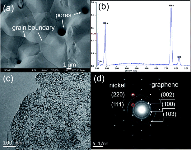 |
| | Fig. 1 (a) SEM image, (b) EDS, (c) TEM image and (d) corroding SAED of G–Ni-3 sample. | |
3.2 Friction coefficient and wear rate
Fig. 2 shows the COF curves of the samples with various sucrose content. It is seen that the COF of the samples remains basically the same when sucrose content is less than 160 mg. This is similar to the experimental results of the graphene–Cu and CNTs–Si3N4 composites.14,15 A possible explanation is that graphene content is too low to form the uniform tribofilms at the friction interface. The COF of the G–Ni-3 sample decreases to 0.39 when sucrose content is 240 mg, which is about 40% lower than that of pure nickel. However, the COF of the G–Ni-4 sample with 1.30 wt% graphene increases reversely when sucrose content further increases to 320 mg. The variation of wear rate of the samples is shown in Fig. 3. Similar to the COF, the wear rate of the samples remains constant within the scatter at low sucrose. Although the COF of samples have an optimum value, wear rate increases abnormally at high sucrose content. The G–Ni-3 sample has the highest hardness value but relatively high wear rate. Obviously, the wear resistance is not correlated to the hardness of the G–Ni composites. Hence, in situ grown graphene has a good self-lubrication effect as graphene content is beyond a critical value, but it do not improve the wear resistance of the composites.
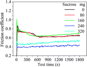 |
| | Fig. 2 The COF curves of the samples with various sucrose content. | |
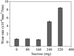 |
| | Fig. 3 The wear rate of the samples with various sucrose content. The error bars represent the minimum and maximum. | |
3.3 Morphology of worn surface
The three-dimensional (3D) surface topography of wear track on the composites after sliding against the steel balls is presented in Fig. 4. As can be seen from the images, the wear track presents shallow and coarse surface at low sucrose content. The wear track become deeper but smoother at high sucrose content, which suggests different wear mechanisms. Accordingly, it can be seen from Fig. 5 that the wear scar formed on the pairing steel ball at low sucrose content is significantly larger than that at high sucrose content.
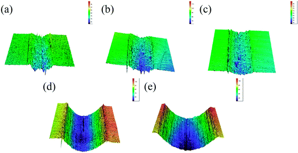 |
| | Fig. 4 3D topographic images of the wear track on the samples: (a) pure Ni, (b) G–Ni-1, (c) G–Ni-2, (d) G–Ni-3 and (e) G–Ni-4. | |
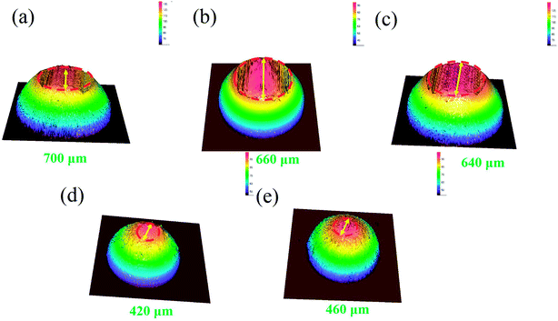 |
| | Fig. 5 3D topographic images of the wear scar on the steel balls against the samples: (a) pure Ni, (b) G–Ni-1, (c) G–Ni-2, (d) G–Ni-3 and (e) G–Ni-4. | |
Fig. 6a–f shows the SEM images of the worn surfaces of the samples and steel balls. The worn surface of pure nickel sample shows the adhesive wear and severe plastic deformation (Fig. 6a). Some debris were transferred and adhered to the steel ball surface (Fig. 6d), because pure nickel matrix is softer than steel ball. After growing graphene in nickel matrix, the worn surface of the G–Ni-3 sample become smoother (Fig. 6b) compared with that of pure Ni sample, because graphene can restrict effectively the plastic deformation. The worn surface presents the shallow ploughing grooves and a few small delaminated craters. Further increasing graphene content, the G–Ni-4 sample occurred the severe delamination damage. The large pieces of delamination and some delaminated cracks are observed on the worn surface (Fig. 6c), leading to a sharp increase in wear rate. The worn surface of steel balls is smooth without large adhesive particles (Fig. 6e and f), and only small debris was accumulated in front of the wear scar, indicating a slight wear of the steel balls. Especially, many fine graphene particles (red circle) can be observed at the edge of the wear scar, which suggests that graphene as solid lubricant in the composites was detached from nickel matrix under interfacial shear stress, then squeezed and smeared under high contact pressure on the worn surface during the friction process. In order to further confirm the formation of the tribofilms, the EDS analysis results of worn scar and debris are shown in Fig. 6g and h. The results show that the worn surface contains carbon and nickel elements with high C/Ni atomic ratios in wear scar (4![[thin space (1/6-em)]](https://www.rsc.org/images/entities/char_2009.gif) :
:![[thin space (1/6-em)]](https://www.rsc.org/images/entities/char_2009.gif) 1) and debris (13
1) and debris (13![[thin space (1/6-em)]](https://www.rsc.org/images/entities/char_2009.gif) :
:![[thin space (1/6-em)]](https://www.rsc.org/images/entities/char_2009.gif) 1). The C/Ni atomic ratios are much higher than that of the pristine sample, which identifies the presence of a thin carbon-rich tribofilms on the worn surface. Hence, it is concluded that carbon species derived from graphene was transferred to the steel ball surface forming the lubricating carbon-rich tribofilms.
1). The C/Ni atomic ratios are much higher than that of the pristine sample, which identifies the presence of a thin carbon-rich tribofilms on the worn surface. Hence, it is concluded that carbon species derived from graphene was transferred to the steel ball surface forming the lubricating carbon-rich tribofilms.
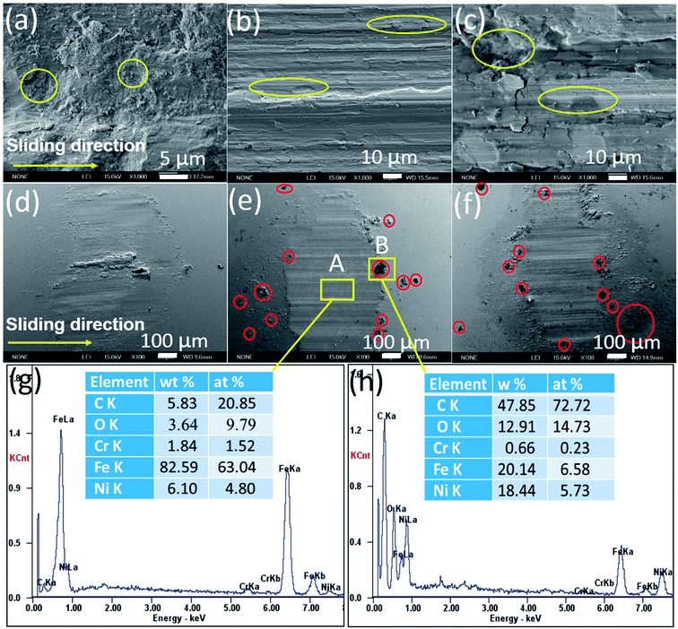 |
| | Fig. 6 SEM images (a–f) and EDS (g and h) of the worn surfaces of (a and d) pure Ni, (b and e) G–Ni-3 and (c and f) G–Ni-4 the samples and the pairing steel balls. | |
3.4 XPS analysis of worn surface
The G–Ni-3 sample and the steel ball were analyzed by means of XPS to explore the tribochemical species on the worn surfaces, and the results are shown in Fig. 7. The survey spectrum obtained from pristine surface of the sample shows the presence of the principal Ni 2p, C 1s and O 1s core levels (Fig. 7a). The Ni 2p3/2 spectrum in Fig. 7b was deconvoluted into three peaks centered at 852.6, 853.7 and 855.9 eV, corresponding to metal Ni, NiO and Ni(OH)2,16,17 respectively, which suggests that the pristine surface of the composite exists a little nickel oxide and hydroxide, probably due to contamination in moist air. It is worthy to note that the peak intensities of NiO and Ni(OH)2 increase significantly in the Ni 2p3/2 spectrum from the worn surface of the sample (Fig. 7c). This indicates that tribochemical reactions resulted in the formation of NiO and Ni(OH)2 species on the worn track during the friction process. The similar tribochemical oxidation were reported by others for the graphene/NiAl and carbon nanotube/Ni composites.18,19 The signal of Fe element was also detected from the worn surface of the sample, as shown in Fig. 7d. The Fe 2p3/2 spectrum was deconvoluted into two components centered at 706.5 and 711.4 eV, corresponding to metal Fe and FeOOH. The presence of iron signal means that the iron was transferred from the steel ball to worn surface of the composite.20 Trace amounts of nickel could also be found on wear scar from the steel ball, as shown in Fig. 7e. A weak metal nickel peak in Ni 2p3/2 spectrum can be distinguished from the background. It is seen in Fig. 7f that the Fe 2p3/2 spectrum was deconvoluted into two components centered at 709.7 and 711.0 eV, corresponding to metal FeO and Fe2O3,21 which suggests that the worn surface of steel ball is oxidized severely. This is consistent with the O 1s spectra in Fig. 8. The O 1s spectra were deconvoluted into three peaks centered at 529.7, 531.5 and 533.0 eV, corresponding to metal oxides Ni(Fe)–O, C–O and C![[double bond, length as m-dash]](https://www.rsc.org/images/entities/char_e001.gif) O bonds. It is noted that the normalized Ni–O peak area in the worn track (0.09) is much smaller than that in the pristine (0.17). This indicates that the tribofilms derived from graphene has a protective role on the wear track because oxygen would react with the carbon first instead of the nickel matrix. The similar effect was also observed by T. W. Scharf et al. in the CNTs–Ni composite.22 However, it does not work well for the steel ball since the normalized Fe–O peak area in the Fig. 8c increased significantly to 0.29. The reason could be that the affinity of oxygen to iron is greater than that to nickel. In Fig. 8d–f, the C 1s spectra were deconvoluted into three peaks centered at 284.8, 286.6, 288.3 eV. The main peak at 284.8 eV corresponds to sp2 hybridization C–C bond of the graphene network, while the peaks at 286.6 and 288.3 eV are attributed to epoxide C–O and carboxyl C
O bonds. It is noted that the normalized Ni–O peak area in the worn track (0.09) is much smaller than that in the pristine (0.17). This indicates that the tribofilms derived from graphene has a protective role on the wear track because oxygen would react with the carbon first instead of the nickel matrix. The similar effect was also observed by T. W. Scharf et al. in the CNTs–Ni composite.22 However, it does not work well for the steel ball since the normalized Fe–O peak area in the Fig. 8c increased significantly to 0.29. The reason could be that the affinity of oxygen to iron is greater than that to nickel. In Fig. 8d–f, the C 1s spectra were deconvoluted into three peaks centered at 284.8, 286.6, 288.3 eV. The main peak at 284.8 eV corresponds to sp2 hybridization C–C bond of the graphene network, while the peaks at 286.6 and 288.3 eV are attributed to epoxide C–O and carboxyl C![[double bond, length as m-dash]](https://www.rsc.org/images/entities/char_e001.gif) O groups in graphene. It is clearly seen that the C–O and C
O groups in graphene. It is clearly seen that the C–O and C![[double bond, length as m-dash]](https://www.rsc.org/images/entities/char_e001.gif) O components in the worn surface of the composite and steel ball are higher than in the pristine sample, which further confirms the tribochemical reactions between graphene and oxygen during the friction process.
O components in the worn surface of the composite and steel ball are higher than in the pristine sample, which further confirms the tribochemical reactions between graphene and oxygen during the friction process.
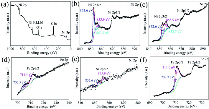 |
| | Fig. 7 XPS survey spectrum and the Ni 2p and Fe 2p core-level XPS spectra obtained from (a and b) the pristine surface and (c and d) worn surface of the G–Ni-3 sample, and (e and f) worn surface of the steel ball. | |
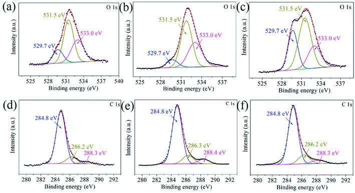 |
| | Fig. 8 The O 1s and C 1s core-level XPS spectra obtained from (a and b) the pristine surface and (c and d) worn surface of the G–Ni-3 sample, and (e and f) worn surface of the steel ball. | |
3.5 Raman analysis of worn surface
Raman spectroscopy has been used to further analyze structure evolution of graphene during the friction process. Raman spectra acquired from the worn surfaces of the sample and steel ball after the friction testing show substantial variation in position, intensity and the full width at half maximum, as shown in Fig. 9a, which implies the tribo-induced structural transformations of graphene. It is seen that the Raman spectrum acquired from surface of the G–Ni-3 sample shows a strong symmetric G peak around 1584 cm−1 and an invisible D peak around 1350 cm−1, indicating the high-quality (defect-free) of graphene. The D peak was fitted well using a Lorentz function centred at 1584.4 cm−1 with the full width at half maximum (FWHM) of 20 cm−1. The Raman spectrum acquired from interior of the G–Ni-3 sample has a prominent D peak, indicating a relatively high defect density in graphene probably due to hydrogen-poor growth process for graphene. The Raman spectra of the G–Ni-3 sample in the region of 1000–2000 cm−1 was fitted to five Lorentz peaks in order to analyze the different components, as shown in Fig. 9b. The D1 peak at 1336.3 cm−1 and the G1 peak at 1550.0 cm−1 are assigned to disordered amorphous carbon, while the D2 peak at 1352.1 cm−1 and the G2 peak at 1585.0 cm−1 are related to graphene. For carbon materials, G peak originates in-plane vibration of pairs of sp2 carbon atoms in both rings and chains, and D peak is due to the presence of defects or disorder structures.23,24 Graphene has a higher vibrational density of states than disordered amorphous carbon, because the sp2 carbon atoms in graphene should have stronger, slightly shorter bonds than in amorphous carbon with sp3 carbon atoms. The weak D′ peak at 1620 cm−1 is an intravalley scattering process, similar to D peak, also relating to structural defects.25 After friction testing, the intensity of G1 peak (IG1) increases significantly, whereas the intensity of G2 peak (IG2) decreases. This variation suggests that graphene may transform from an intact structure with less defects to amorphous structure due to the increasing of defects introduced by the friction process. This is also supported by the decrease of 2D peak at 2700 cm−1 due to defect induced suppression of the lattice vibration mode, and the emergence of a broad D + G (CHx) peak at about 2900 cm−1 as an indicator of structural disorder in graphene. Furthermore, it is observed that the G2 peak shifts 6 cm−1 toward higher frequency. Recently, Ni and Park et al.26,27 observed this shift of Raman spectrum as graphene was annealed at elevated temperatures. Z. Ni attributed the significant blueshift of the Raman spectra to the strong compressive stress on graphene. Park et al. believed that ambient oxygen molecules intercalate through the interface between graphene and substrate and undergo a redox reaction that injects holes into the graphene.27 This annealing-induced interfacial hole doping can also lead to the blueshift of spectra. It is reasonable to suppose that graphene would experience a similar annealed process because the friction can elevate the temperature at the sliding interface. Hence, the tribo-induced chemical reactions between graphene and oxygen may cause the shift of G1 peak. Another possible reason is graphitization of graphene caused by the sliding friction.18 From the Raman spectrum acquired from the steel ball shown in Fig. 8d, we have noticed, most surprisingly, the three weak peaks located at 870, 1060 and 1220 cm−1. The peak at 870 cm−1 can be attributed to the defects in sp2 aromatic rings, which is Raman inactive but became Raman active due to the relaxation of the Raman selection rules in graphite,28 while the peaks at 1220 and a companion at 1060 cm−1 are assigned to polymer-like structure such as transpolyacetylene and neutral p-phenylene vinylene,29,30 which was usually observed in hydrogenated amorphous carbon films.28,30 The polymer-like chains or segments may be generated by breaking of sixfold aromatic rings and bonding with hydrogen atoms, because the friction can increase the chemical activity of sliding interface in the presence of nickel catalysts.31 Scharf32 confirmed by Time-of-Flight Secondary Ion Mass Spectroscopy that the polymeric segments was generated by the polymerization of hydrogenated diamond-like carbon film during the friction process.
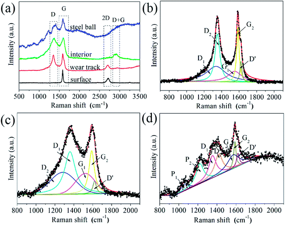 |
| | Fig. 9 (a) Raman spectra of the G–Ni-3 sample before and after friction testing, and the worn surface of the steel ball sliding against the G–Ni-3 sample; the deconvolution of Raman spectra of (b) interior of the G–Ni-3 sample, and the worn surfaces of (c) the G–Ni-3 sample and (d) the steel ball. | |
4. Conclusions
G–Ni composites were in situ fabricated using a facile powder metallurgy method. The effect of graphene content on the tribological behavior of the G–Ni composites were investigated. The results show that in situ grown graphene exhibits a good self-lubrication effect as graphene content reach 0.99 wt%, but it do not improve the wear resistance of the G–Ni composite due to abrasive wear and severe delamination. The XPS and Raman results reveal that graphene not only protects nickel matrix from severe oxidation at the expenses of its oxidation, but also forms the carbon-rich tribofilms containing disordered amorphous carbon and ordered polymers by tribo-induced chemical reactions. These experimental results provide the evidences of tribochemistry which can help us to understand the self-lubricating roles of graphene in G–Ni composites.
Conflicts of interest
There are no conflicts to declare.
Acknowledgements
This work was supported by the National Natural Science Foundation of China (51741104) and Open Fund Project of National United Engineering Laboratory for Advanced Bearing Tribology (201706).
References
- A. D. Moghadam, E. Omrani, P. L. Menezes and P. K. Rohatgi, Mechanical and tribological properties of self-lubricating metal matrix nanocomposites reinforced by carbon nanotubes (CNTs) and graphene-A review, Composites, Part B, 2015, 77, 402–420 CrossRef.
- H. Luo, Y. Sui, J. Qi, Q. Meng, F. Wei and Y. He, Mechanical enhancement of copper matrix composites with homogeneously dispersed graphene modified by silver nanoparticles, J. Alloys Compd., 2017, 729, 293–302 CrossRef CAS.
- Y. Zhang, H. Tang, X. Ji, C. Li, L. Chen, D. Zhang, X. Yang and H. Zhang, Synthesis of reduced graphene oxide/Cu nanoparticle composites and their tribological properties, RSC Adv., 2013, 3, 26086–26093 RSC.
- H. Algul, M. Tokur, S. Ozcan, M. Uysal, T. Cetinkaya, H. Akbulut and A. Alp, The effect of graphene content and sliding speed on the wear mechanism of nickel-graphene nanocomposites, Appl. Surf. Sci., 2015, 359, 340–348 CrossRef CAS.
- C. Testani and M. Tului, Improved performance in aerospace structures with Ti and Ni metal matrix composites, Mater. Sci. Forum, 2012, 706–709, 240–245 Search PubMed.
- L. You, G. Wang, S. Liu, S. Zhao and K. Zhang, The preparation of Ni/GO composite foils and the enhancement effects of GO in mechanical properties, Composites, Part B, 2018, 135, 43–48 CrossRef.
- Z. Xu, Q. Zhang, X. Shi, W. Zhai and Q. Zhu, Comparison of tribological properties of NiAl matrix composites containing graphite, carbon nanotubes, or graphene, J. Mater. Eng. Perform., 2015, 24, 1926–1936 CrossRef CAS.
- A. M. M. Ibrahim, X. Shia, A. Zhang, K. Yang and W. Zhai, Tribological characteristics of NiAl matrix composites with 1.5 wt.% graphene at elevated temperatures: An experimental and theoretical study, Tribol. Int., 2015, 58, 1076–1083 CAS.
- W. Zhai, X. Shi, J. Yao, A. M. M. Ibrahim, Z. Xu, Q. Zhu, Y. Xiao, L. Chen and Q. Zhang, Investigation of mechanical and tribological behaviors of multilayer graphene reinforced Ni3Al matrix composites, Composites, Part B, 2015, 70, 149–155 CrossRef CAS.
- W. Zhai, X. Shi, Z. Xu and A. Zhang, Investigation of the friction layer of Ni3Al matrix composites, Wear, 2015, 328–329, 39–49 CrossRef CAS.
- Q. Zhu, X. Shi, W. Zhai, J. Yao, A. M. M. Ibrahim, Z. Xu, S. Song, A. Q. ud Din, L. Chen, Y. Xiao and Q. Zhang, Effect of counterface balls on the friction layer of Ni3Al matrix composites with 1.5 wt.% graphene nanoplatelets, Tribol. Lett., 2014, 55, 343–352 CrossRef CAS.
- W. Zhai, X. Shi, M. Wang, Z. Xu, J. Yao, S. Song and Y. Wang, Grain refinement: A mechanism for graphene nanoplatelets to reduce friction and wear of Ni3Al matrix self-lubricating composites, Wear, 2014, 310, 33–40 CrossRef CAS.
- J. Jiang, X. He, J. Du, X. Pang, H. Yang and Z. Wei, In-situ fabrication of graphene-nickel matrix composites, Mater. Lett., 2018, 220, 178–181 CrossRef CAS.
- F. Chen, J. Ying, Y. Wang, S. Du, Z. Liu and Q. Huang, Effects of graphene content on the microstructure and properties of copper matrix composites, Carbon, 2016, 96, 836–842 CrossRef CAS.
- P. Hvizdoš, J. Dusza and C. Balázsi, Tribological properties of Si3N4-graphene nanocomposites, J. Eur. Ceram. Soc., 2013, 33, 2359–2364 CrossRef.
- Z. Qi and W. Lee, XPS study of CMP mechanisms of NiP coating for hard disk drive substrates, Tribol. Int., 2010, 43, 810–814 CrossRef CAS.
- A. P. Grosvenor, M. C. Biesinger, R. S. C. Smar and N. S. Mcintyre, New interpretations of XPS spectra of nickel metal and oxides, Surf. Sci., 2006, 600, 1771–1779 CrossRef CAS.
- B. Li, J. Jia, Y. Gao, M. Han and W. Wang, Microstructural and tribological characterization of NiAl matrix self-lubricating composite coatings by atmospheric plasma spraying, Tribol. Int., 2017, 109, 563–570 CrossRef CAS.
- S. R. Dong, J. P. Tu and X. B. Zhang, An investigation of the sliding wear behavior of Cu-matrix composite reinforced by carbon nanotubes, Mater. Sci. Eng., 2001, 313, 83–87 CrossRef.
- I. Minami and A. Sugibuchi, Surface chemistry of aluminium alloy slid against steel lubricated by organic friction modifier in hydrocarbon oil, Adv. Tribol., 2012, 92, 68–70 Search PubMed.
- H. Mano, K. Miyake, M. Nakano, A. Korenaga, T. Murakami, S. Sasaki and J. Sugimura, Effects of residual gas on tribochemical reactions of SUJ2 steel in vacuum and in argon gas atmosphere, Tribology Online, 2009, 4, 103–108 CrossRef.
- T. W. Scharf, A. Neira, J. Y. Hwang, J. Tiley and R. Banerjee, Self-lubricating carbon nanotube reinforced nickel matrix composites, J. Appl. Phys., 2009, 106, 013508 CrossRef.
- Z. Ni, Y. Wang, T. Yu and Z. Shen, Raman spectroscopy and imaging of graphene, Nano Res., 2008, 1, 273–291 CrossRef CAS.
- A. C. Ferrari and J. Robertson, Interpretation of Raman spectra of disordered and amorphous carbon, Phys. Rev. B: Condens. Matter Mater. Phys., 2000, 61, 14095–14107 CrossRef CAS.
- L. M. Malard, M. A. Pimenta, G. Dresselhaus and M. S. Dresselhaus, Raman spectroscopy in graphene, Phys. Rep., 2009, 473, 51–87 CrossRef CAS.
- Z. H. Ni, H. M. Wang, Y. Ma, J. Kasim, Y. H. Wu and Z. X. Shen, Tunable stress and controlled thickness modification in graphene by annealing, ACS Nano, 2008, 2, 1033–1039 CrossRef CAS.
- K. Park and S. Ryu, Direction-controlled chemical doping for reversible G-phonon mixing in ABC trilayer graphene, Sci. Rep., 2015, 5, 8707 CrossRef CAS.
- R. Arenal and A. C. Y. Liu, Clustering of aromatic rings in near-frictionless hydrogenated amorphous carbon films probed using multiwavelength Raman spectroscopy, Appl. Phys. Lett., 2007, 91, 211903 CrossRef.
- M. Rybachuk, A. Hu and J. M. Bell, Resonant Raman scattering from polyacetylene and poly (p-phenylene vinylene) chains included into hydrogenated amorphous carbon, Appl. Phys. Lett., 2008, 93, 051904 CrossRef.
- J. Jiang, J. Hao, P. Wang and W. Liu, Superlow friction of titanium/silicon codoped hydrogenated amorphous carbon film in the ambient air, J. Appl. Phys., 2010, 108, 033510 CrossRef.
- A. Erdemir, G. Ramirez, O. L. Eryilmaz, B. Narayanan, Y. Liao, G. Kamath and S. K. Sankaranarayanan, Carbon-based tribofilms from lubricating oils, Nature, 2016, 536, 67–71 CrossRef CAS.
- T. W. Scharf, J. A. Ohlhausen, D. R. Tallant and S. V. Prasad, Mechanisms of friction in diamond like nanocomposite coatings, J. Appl. Phys., 2007, 101, 063521 CrossRef.
|
| This journal is © The Royal Society of Chemistry 2018 |
Click here to see how this site uses Cookies. View our privacy policy here.  Open Access Article
 *abc,
Tiantian
Bi
b,
Jinfang
Du
b and
Xianjuan
Pang
c
 , where mg is the mass of graphene, ms is the mass of sucrose, M(C12H22O11) is molecular mass of sucrose, and M(C12) is mass of carbon atoms in a molecule of sucrose. The calculated graphene mass fraction in the composites is listed in Table 1. Although the theoretical graphene fraction was about 0.34 wt% for 80 mg sucrose, no graphene was detected by Raman spectra because carbon atoms were dissolved in nickel forming a solid solution at the low sucrose content.


![[thin space (1/6-em)]](https://www.rsc.org/images/entities/char_2009.gif) :
:![[thin space (1/6-em)]](https://www.rsc.org/images/entities/char_2009.gif) 1) and debris (13
1) and debris (13![[thin space (1/6-em)]](https://www.rsc.org/images/entities/char_2009.gif) :
:![[thin space (1/6-em)]](https://www.rsc.org/images/entities/char_2009.gif) 1). The C/Ni atomic ratios are much higher than that of the pristine sample, which identifies the presence of a thin carbon-rich tribofilms on the worn surface. Hence, it is concluded that carbon species derived from graphene was transferred to the steel ball surface forming the lubricating carbon-rich tribofilms.
1). The C/Ni atomic ratios are much higher than that of the pristine sample, which identifies the presence of a thin carbon-rich tribofilms on the worn surface. Hence, it is concluded that carbon species derived from graphene was transferred to the steel ball surface forming the lubricating carbon-rich tribofilms.
![[double bond, length as m-dash]](https://www.rsc.org/images/entities/char_e001.gif) O bonds. It is noted that the normalized Ni–O peak area in the worn track (0.09) is much smaller than that in the pristine (0.17). This indicates that the tribofilms derived from graphene has a protective role on the wear track because oxygen would react with the carbon first instead of the nickel matrix. The similar effect was also observed by T. W. Scharf et al. in the CNTs–Ni composite.22 However, it does not work well for the steel ball since the normalized Fe–O peak area in the Fig. 8c increased significantly to 0.29. The reason could be that the affinity of oxygen to iron is greater than that to nickel. In Fig. 8d–f, the C 1s spectra were deconvoluted into three peaks centered at 284.8, 286.6, 288.3 eV. The main peak at 284.8 eV corresponds to sp2 hybridization C–C bond of the graphene network, while the peaks at 286.6 and 288.3 eV are attributed to epoxide C–O and carboxyl C
O bonds. It is noted that the normalized Ni–O peak area in the worn track (0.09) is much smaller than that in the pristine (0.17). This indicates that the tribofilms derived from graphene has a protective role on the wear track because oxygen would react with the carbon first instead of the nickel matrix. The similar effect was also observed by T. W. Scharf et al. in the CNTs–Ni composite.22 However, it does not work well for the steel ball since the normalized Fe–O peak area in the Fig. 8c increased significantly to 0.29. The reason could be that the affinity of oxygen to iron is greater than that to nickel. In Fig. 8d–f, the C 1s spectra were deconvoluted into three peaks centered at 284.8, 286.6, 288.3 eV. The main peak at 284.8 eV corresponds to sp2 hybridization C–C bond of the graphene network, while the peaks at 286.6 and 288.3 eV are attributed to epoxide C–O and carboxyl C![[double bond, length as m-dash]](https://www.rsc.org/images/entities/char_e001.gif) O groups in graphene. It is clearly seen that the C–O and C
O groups in graphene. It is clearly seen that the C–O and C![[double bond, length as m-dash]](https://www.rsc.org/images/entities/char_e001.gif) O components in the worn surface of the composite and steel ball are higher than in the pristine sample, which further confirms the tribochemical reactions between graphene and oxygen during the friction process.
O components in the worn surface of the composite and steel ball are higher than in the pristine sample, which further confirms the tribochemical reactions between graphene and oxygen during the friction process.


