
 Open Access Article
 This Open Access Article is licensed under a Creative Commons Attribution-Non Commercial 3.0 Unported Licence
Facile synthesis of hollow hierarchical Ni@C nanocomposites with well-dispersed high-loading Ni nanoparticles embedded in carbon for reduction of 4-nitrophenol†
Xiaodi Guo ab,
Hongpeng Kanb,
Xinxin Liub,
Hongshuai Gengb and
Lianying Wang*b
ab,
Hongpeng Kanb,
Xinxin Liub,
Hongshuai Gengb and
Lianying Wang*b
aCollege of Arts and Sciences, Shanxi Agricultural University, Taigu, Shanxi 030801, P. R. China
bState Key Laboratory of Chemical Resource Engineering, Beijing University of Chemical Technology, Beijing, 100029, P. R. China. E-mail: wangliany@mail.buct.edu.cn; Tel: +86 10 64451027
First published on 30th April 2018
Abstract
Hollow hierarchical Ni@C nanocomposites with highly dispersed Ni nanoparticles (NPs) embedded in well-graphitized carbon matrix have been synthesized by solid-state pyrolysis of simple, well-defined organic–inorganic layered nickel hydroxide. The integration of highly dispersed Ni NPs, high Ni NPs content (up to ∼88.01 wt%), well-graphitized carbon as well as strong Ni/carbon interaction in the Ni@C make them display excellent catalytic activity and stable magnetic recyclability toward the reduction of 4-nitrophenol by NaBH4.
The development of more efficient and stable catalysts has been an increasingly important goal for chemists and materials scientists for both economic and environmental reasons. As efficient and cost-effective non-noble metal, Ni NPs have attracted much attention owing to their potential applications in electronic or optical materials, as well as in catalysis.1–3 In general, the overall performance of Ni NPs depends heavily upon the size, shape and dispersion. It is widely accepted that a higher catalytic activity can be achieved by increasing the surface area of the specific active phase of the catalysts through reducing the size of the corresponding catalytic particles.4–7 However, due to their high surface area to volume ratio, Ni NPs are typically unstable and tend to sinter into larger species, especially at high metal contents, which results in a dramatic decrease in catalytic activity and selectivity. It is thus highly important to prepare stable Ni NPs with uniform dispersion and narrow size distribution to promote their catalytic activities.
Over the past decades, embedding of Ni NPs inside the porous supports has been proved to enhance catalytic activity and impede nanoparticle sintering.8–15 The advantages of carbon supports with respect to conventional oxidic supports, like silica and zirconia, involve the high specific surface area, high stability, intrinsic high electrical conductivity, as well as easy recovery of metal active phases from spent catalysts by burning away carbon. To date, various methods for preparing carbon-supported Ni NPs have been developed.16–22 In particular, incipient wetness impregnation and coprecipitation are commonly used methods to prepare these supported catalysts. It is well known that traditional carbons (including activated carbon, carbon nanotubes, graphene and carbon nanofibers) are poor in functional groups and a complex functionalization pre-treatment (such as acid oxidation, ionic liquid linking or polymer wrapping) is always required. In addition, the excess reducing regents are also needed for the reduction of Ni NPs. Although a high dispersion of Ni NPs on porous carbon can be achieved by employing this methods, this tedious post-synthetic method renders instable catalysts with dispersed Ni NPs on the external surface or near pore mouths and Ni NPs still have a tendency to be sintered, especially at high metal loading or high temperature, resulting in a significant loss of reactivity because of the relatively weak interaction between supported metal and carbon supports. Therefore, methods for the large-scale fabrication of carbon supported Ni NPs without using any reducing agents and high resistance toward sintering at high a metal loading level or a high temperature are still needed.
Recently, precursor-controlled pyrolysis of polymer frameworks have proven an attractive template-free, one-step approach toward creating novel metal–carbon hybrids with uniformly distributed metal NPs in a carbon matrix.23–26 Taking advantage of this category of the systems, we demonstrate a facile synthetic route to fabricate hollow hierarchical Ni@C nanocomposite by one-step solid-state pyrolysis of a simple and inexpensive organic–inorganic layered nickel hydroxides. In this facile procedure, cheap commercially available nickel nitrate hexahydrate and sodium salicylate are used as starting materials, and during the pyrolysis process the interlayer salicylate anions act as carbon source and reducing agent without the need for any external agent or surface modification. In the composites, well-crystallized Ni NPs with high loading content (88.01 wt%) are uniformly embedded in the well-graphitized carbon matrix. The as-prepared Ni@C nanocomposites show excellent catalytic activity toward the reduction of 4-NP by NaBH4 and can be easily magnetically recovered and reused for several cycles.
The hierarchical layered nickel hydroxides intercalated with salicylate anions (LNHs–Sal) precursor was prepared in large quantities through a simple urea decomposition method in water (details of the experimental are given in the ESI†). The X-ray diffraction (XRD) pattern (Fig. S1†) of precursor exhibits the typical pattern of a layered structure with very well-ordered (00l) basal peaks at low angle, confirming the successful intercalation of salicylate anions.27 The scanning electron microscopy (SEM) image (Fig. S2†) displays the hierarchical LNHs–Sal microsphere (∼1.5 μm in diameter) composed of numerous frizzy nanoflakes intercrossing with each other. EDX spectra (Fig. S3†) shows the presence of Ni, O, C (with additional Pt signals arising from the Pt coating). Based on the elemental analysis, the chemical composition of the LNHs–Sal can be written as Ni(OH)1.676(C7H5O3)0.324·0.279H2O (anal calcd: C 19.95, H 2.816%. Found: C 19.93, H 2.821%).
The LNHs–Sal was directly carbonized at 500 °C for 2 h under N2 flow. Fig. 1a shows the typical SEM image of the product, which displays large-scale particles. Interestingly, we find that the configuration of the hollow flower-like morphology was perfectly maintained after thermal treatment (Fig. 1a and b), indicative of the high thermal stability of a self-assembled three-dimensional nanostructure. EDX result shows that the hollow flower-like nanocomposites consisted of nickel, carbon and oxygen (Fig. S4†). As revealed by transmission electron microscopy (TEM) image (Fig. 1c), it can be seen that shell thickness of hollow Ni@C nanocomposites is ∼200 nm, close to the lateral size of LNHs–Sal nanoflakes. XRD pattern of products is shown in Fig. 1d, three peaks appeared at 44.51, 51.85, 76.45° can be attributed to the (111), (200) and (220) planes, respectively, of fcc-Ni (JCPDF: 04-0850),28 suggesting the successful in situ reduction of the Ni ions to a metallic state after carbonization. No peaks of impurities could be detected from this pattern, indicating the high purity of the materials.
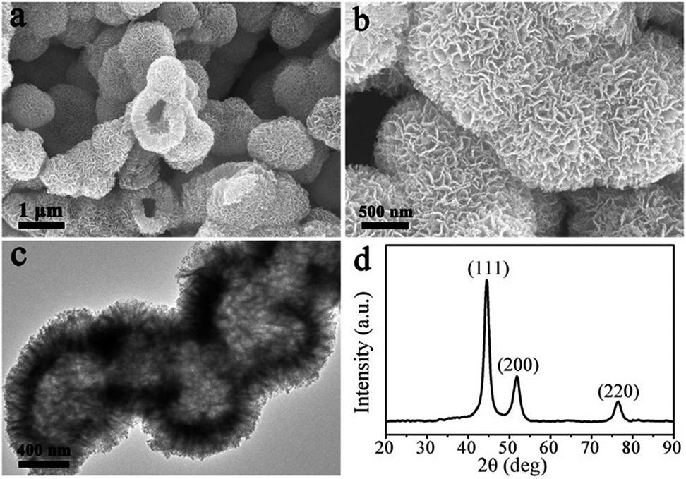 | ||
| Fig. 1 (a) and (b) SEM images, (c) TEM image, and (d) XRD of Ni@C nanocomposites. | ||
High resolution transmission electron microscopy (HRTEM) of the Ni@C nanocomposites are shown in Fig. 2. Although no characteristic XRD pattern of graphitic carbon is observed directly (Fig. 1d), well-graphitized layers and lattice fringes are observed in the surroundings of Ni NPs (Fig. 2b and c), suggestive of the nature of graphitic carbon, which is also confirmed by the Raman spectra (Fig. S5†). Notable, the sizes of the Ni NPs are limited to ∼9 nm, which is well consistent with the XRD results estimated by Debye–Scherrer equation. The Ni NPs are homogeneously dispersed within the well-graphitized carbon matrix without aggregation even if the Ni content is up to ∼88.01 wt%, which was evaluated by the result of the TG under air (Fig. S6†), indicating an excellent confinement that can avoid sintering of the Ni NPs (Fig. 2c). Such superior confinement can be attributed to the in situ simultaneous formation of Ni NPs and carbon matrix during the high-temperature thermal treatment, where the Ni NPs formed were firmly locked within the carbon matrix.29,30 The lattice distance of 0.203 nm (Fig. 2d), corresponding to the (111) planes of the fcc metallic nickel phase, is in good accordance with the unit cell given by XRD.
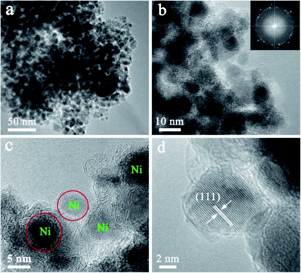 | ||
| Fig. 2 (a) TEM image, (b)–(d) HRTEM image of Ni@C nanocomposites. | ||
X-ray photoelectron spectroscopy (XPS) measurement was performed to investigate the specific surface composition and chemical environment of the representative Ni@C nanocomposites. Two principal peaks in the Ni 2p XPS spectrum (Fig. 3a) centered at 852.9 and 870.2 eV confirmed the metallic state of Ni in Ni@C.31–33 While Ni 2p doublet with the binding energies of 856.3 and 874.3 eV, may be attributed to the Ni–O–C on the surface of Ni nanoparticles, indicates the formation of strong interaction between the Ni NPs and the carbon matrix.34,35 In the expanded image of the C 1s peak (Fig. 3b), the high-resolution C 1s core-level spectrum could be deconvoluted into three peaks centered at ∼284.9, ∼285.9, and ∼289.2 eV, which was indexed to C![[double bond, length as m-dash]](https://www.rsc.org/images/entities/char_e001.gif) C/C–C, C–OH and C–O–Ni, respectively.36–38 The sharpest peak corresponding to CC/C–C indicated that most of the carbon atoms were in the form of a conjugated honeycomb lattice. The O 1s spectrum is deconvoluted into two peaks (Fig. 3c), and they can be assigned to C–O–Ni (530.2 eV) and surface C–OH (532.1 eV).39 These results indicate that strong Ni–O–C interaction was formed, which is very important for preventing the aggregation of the Ni NPs and making the Ni NPs hard to detach from the carbon support (improving the stability). Meanwhile, the external surfaces of Ni@C nanocomposites are extensively functionalized with C–OH groups without any steps of modification, which are derived from the functional groups of salicylate anions and further confirmed by FTIR spectroscopy (Fig. S7†) allowing the Ni@C nanocomposites to be dispersed in water to a certain extent. The Brunauer–Emmett–Teller (BET) surface area of the Ni@C nanocomposites was measured to be 106.11 m2 g−1, and the pore size was about 12.0 nm (Fig. 3d). This should offer a sufficient interface to facilitate to the mass transfer and facilitates the catalytic activity.
C/C–C, C–OH and C–O–Ni, respectively.36–38 The sharpest peak corresponding to CC/C–C indicated that most of the carbon atoms were in the form of a conjugated honeycomb lattice. The O 1s spectrum is deconvoluted into two peaks (Fig. 3c), and they can be assigned to C–O–Ni (530.2 eV) and surface C–OH (532.1 eV).39 These results indicate that strong Ni–O–C interaction was formed, which is very important for preventing the aggregation of the Ni NPs and making the Ni NPs hard to detach from the carbon support (improving the stability). Meanwhile, the external surfaces of Ni@C nanocomposites are extensively functionalized with C–OH groups without any steps of modification, which are derived from the functional groups of salicylate anions and further confirmed by FTIR spectroscopy (Fig. S7†) allowing the Ni@C nanocomposites to be dispersed in water to a certain extent. The Brunauer–Emmett–Teller (BET) surface area of the Ni@C nanocomposites was measured to be 106.11 m2 g−1, and the pore size was about 12.0 nm (Fig. 3d). This should offer a sufficient interface to facilitate to the mass transfer and facilitates the catalytic activity.
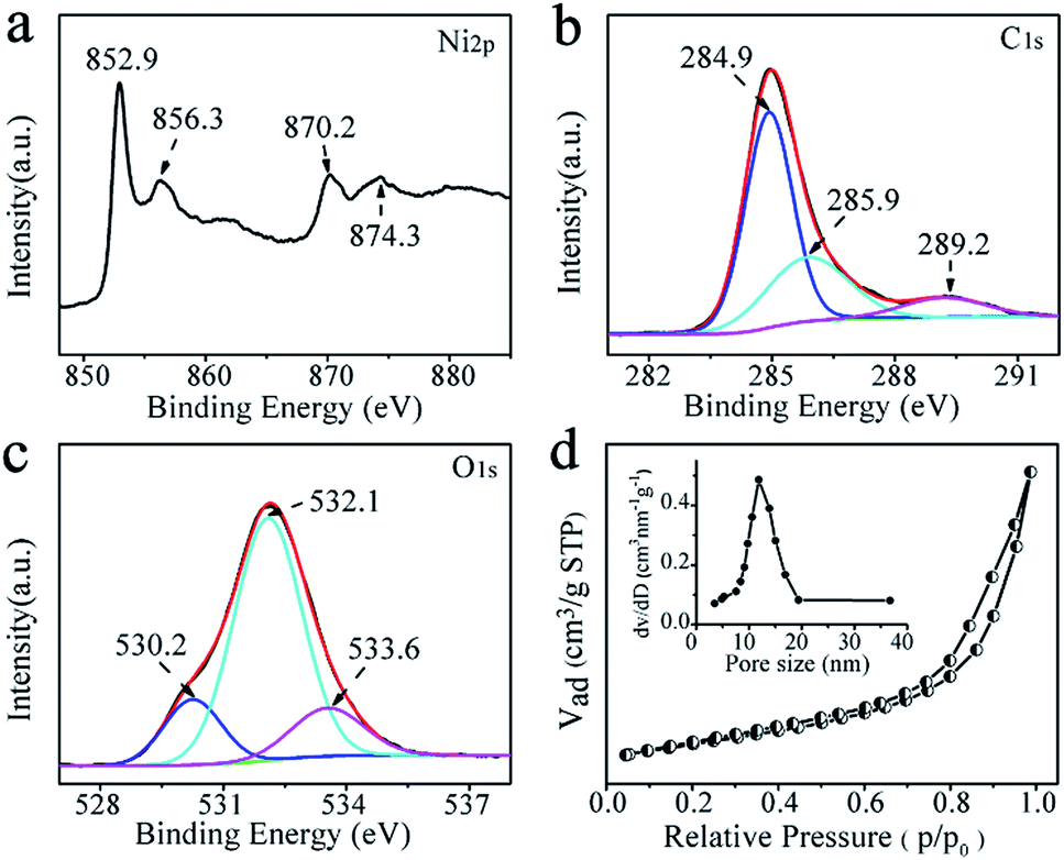 | ||
| Fig. 3 XPS spectra of Ni@C nanocomposites: (a) Ni 2p core levels, (b) C1 core level, and (c) O1 core level; (d) nitrogen adsorption–desorption isotherm Ni@C nanocomposites (inset is pore size distributions). | ||
The catalytic performance of the Ni@C nanocomposites for the reduction of 4-NP to 4-AP with excess of NaBH4 were evaluated, of which the results are show in Fig. 4. In the absence of the catalyst, the peak remained unaltered with time, indicating that the reduction reaction did not occur. With the Ni@C catalyst added, the reduction reaction did proceed. The reaction kinetics could be monitored easily from the time-dependent absorption spectra, which showed the successive intensity decrease of the absorption peak at 400 nm, ascribed to nitro compounds, and the concomitant development of a new peak at 300 nm corresponding to 4-AP, the reduction product of 4-NP (Fig. 4a). In the reduction process, as excess NaBH4 was used, the BH4− concentration can be considered as a constant throughout the reaction. The ratio of Ct and C0, where Ct and C0 are 4-NP concentrations at time t and 0, respectively, was measured from the relative intensity of the respective absorbances, At/A0. The rate constant k can be determined from the linear plot of ln(Ct/C0) versus reduction time was in seconds. As expected, a good linear correlation of ln(Ct/C0) versus time was obtained (Fig. 4b), whereby a kinetic reaction rate constant k over the weight of catalyst is estimated to be 6.43 s−1 g−1, which is larger than those reported previously (Table 1).40–44 The high activity arises from the synergistic effect of carbon matrix and embedded Ni NPs, explained as follows: (1) carbon layers has high adsorption ability towards 4-NP via π–π stacking interactions. This provides a high concentration of 4-NP near to the Ni nanoparticles embedded in carbon matrix, leading to highly efficient contact between them; and (2) the synergistic effect of Ni nanocrystals and well-graphitized carbon matrix, facilitating the uptake of electrons by 4-NP molecules. As shown in Fig. 4c and d, the catalysts can be successfully recycled by an external magnet after the catalytic reduction and reused in 10 successive reactions with a conversion of 87%, further suggesting an excellent stability and long life, which make the products be attractive materials for various potential applications.
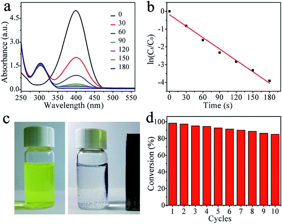 | ||
| Fig. 4 (a) UV-vis spectra of the reduction of 4-NP in aqueous solution using (Ni@C) nanocomposites, (b) the relationship between ln(Ct/C0) and reaction time, (c) magnetic separation and recycling of Ni@C nanocomposite, and (d) conversion of 4-NP in ten successive cycles of reduction. | ||
In summary, we have successfully developed a novel, efficient and scalable strategy for the development of advanced hollow hierarchical Ni@C catalysts with highly dispersed Ni NPs embedded in the well-graphitized carbon matrix by using organic–inorganic layered nickel hydroxides as single-source precursors. The integration of highly dispersed embedded Ni NPs, high Ni NPs content (up to ∼88.01 wt%), well-graphitized carbon matrix as well as strong interaction between the Ni NPs and carbon in the Ni@C catalysts make them excellent active, stable catalysts toward the reduction of 4-NP by NaBH4. The catalysts can be successfully recycled by an external magnet after the catalytic reduction and reused for at least ten successive cycles of reaction with stable conversion efficiency of around 87%, which make the products be attractive materials for various potential applications. This work offers a facile, cost-effective, and green strategy to rationally design and synthesize multifunctional nanomaterials for future applications in catalysis, magnetism, separation, and electrochemistry.
Conflicts of interest
There are no conflicts to declare.Notes and references
- L. Zhou, M. Wen, Q. Wu and D. Wu, Dalton Trans., 2014, 43, 7924–7929 RSC.
- A. Wang, H. Yin, H. Lu, J. Xue, M. Ren and T. Jiang, Langmuir, 2009, 25, 12736–12741 CrossRef CAS PubMed.
- X. Liu, X. Wang, X. Yuan, W. Dong and F. Huang, J. Mater. Chem. A, 2016, 4, 167–172 CAS.
- M.-Q. Zhao, Q. Zhang, W. Zhang, J.-Q. Huang, Y. Zhang, D. S. Su and F. Wei, J. Am. Chem. Soc., 2010, 132, 14739–14741 CrossRef CAS PubMed.
- K. K. R. Datta, B. V. Subba Reddy, K. Ariga and A. Vinu, Angew. Chem., Int. Ed., 2010, 49, 5961–5965 CrossRef CAS PubMed.
- A. L. M. da Silva, J. P. den Breejen, L. V. Mattos, J. H. Bitter, K. P. de Jong and F. B. Noronha, J. Catal., 2014, 318, 67–74 CrossRef CAS.
- P. Munnik, P. E. de Jongh and K. P. de Jong, J. Am. Chem. Soc., 2014, 136, 7333–7340 CrossRef CAS PubMed.
- Ö. Metin, V. Mazumder, S. Özkar and S. Sun, J. Am. Chem. Soc., 2010, 132, 1468–1469 CrossRef PubMed.
- S. Li, C. Zhang, Z. Huang, G. Wu and J. Gong, Chem. Commun., 2013, 49, 4226–4228 RSC.
- M. Lan, G. Fan, Y. Wang, L. Yang and F. Li, J. Mater. Chem. A, 2014, 2, 14682–14689 CAS.
- M. Raula, M. H. Rashid, S. Lai, M. Roy and T. K. Mandal, ACS Appl. Mater. Interfaces, 2012, 4, 878–889 CAS.
- Z. Ren, F. Zhang, L. Yue, X. Li, Y. Tao, G. Zhang, K. Wu, C. Wang and B. Li, RSC Adv., 2015, 5, 52658–52666 RSC.
- X. Li, D. Li, H. Tian, L. Zeng, Z. Zhao and J. Gong, Appl. Catal., B, 2017, 202, 683–694 CrossRef CAS.
- Q. Su, L. Gu, Y. o. Yao, J. Zhao, W. Ji, W. Ding and C.-T. Au, Appl. Catal., B, 2017, 201, 451–460 CrossRef CAS.
- H. Wang, L. Wu, A. Jia, X. Li, Z. Shi, M. Duan and Y. Wang, Chem. Eng. J., 2018, 332, 637–646 CrossRef CAS.
- M. K. van der Lee, A. J. van Dillen, J. H. Bitter and K. P. de Jong, J. Am. Chem. Soc., 2005, 127, 13573–13582 CrossRef CAS PubMed.
- S. Bai, X. Shen, G. Zhu, M. Li, H. Xi and K. Chen, ACS Appl. Mater. Interfaces, 2012, 4, 2378–2386 CAS.
- Y. Wu, M. Wen, Q. Wu and H. Fang, J. Phys. Chem. C, 2014, 118, 6307–6313 CAS.
- T. Wang, Z. Dong, T. Fu, Y. Zhao, T. Wang, Y. Wang, Y. Chen, B. Han and W. Ding, Chem. Commun., 2015, 51, 17712–17715 RSC.
- S. K. Singh, D. Kumar, V. M. Dhavale, S. Pal and S. Kurungot, Adv. Mater. Interfaces, 2016, 3, 1600532 CrossRef.
- L. Wang, Y. Li, M. Xia, Z. Li, Z. Chen, Z. Ma, X. Qin and G. Shao, J. Power Sources, 2017, 347, 220–228 CrossRef CAS.
- I. L. Soroka, N. V. Tarakina, A. Hermansson, L. Bigum, R. Widerberg, M. S. Andersson, R. Mathieu, A. R. Paulraj and Y. Kiros, Dalton Trans., 2017, 46, 9995–10002 RSC.
- L. Shang, H. Yu, X. Huang, T. Tian, R. Shi, Y. Zhao, G. I. N. Waterhouse, L.-Z. Wu, C.-H. Tung and T. Zhang, Adv. Mater., 2015, 1–7 Search PubMed.
- X. Kang, H. Liu, M. Hou, X. Sun, H. Han, T. Jiang, Z. Zhang and B. Han, Angew. Chem., Int. Ed., 2016, 55, 1080–1084 CrossRef CAS PubMed.
- X. Chen, K. Shen, J. Chen, B. Huang, D. Ding, L. Zhang and Y. Li, Chem. Eng. J., 2017, 330, 736–745 CrossRef CAS.
- Y. Xu, W. Tu, B. Zhang, S. Yin, Y. Huang, M. Kraft and R. Xu, Adv. Mater., 2017, 1–8 Search PubMed.
- X. Guo, G. Liu, S. Yue, J. He and L. Wang, RSC Adv., 2015, 5, 96062–96066 RSC.
- H. Y. Wang and A. C. Lua, J. Phys. Chem. C, 2012, 116, 26765–26775 CAS.
- C. An, G. Liu, L. Li, Y. Wang, C. Chen, Y. Wang, L. Jiao and H. Yuan, Nanoscale, 2014, 6, 3223–3230 RSC.
- W. Xia, R. Zou, L. An, D. Xia and S. Guo, Energy Environ. Sci., 2015, 8, 568–576 CAS.
- P.-Z. Li, A. Aijaz and Q. Xu, Angew. Chem., Int. Ed., 2012, 51, 6753–6756 CrossRef CAS PubMed.
- X. Liu, X. Wang, X. Yuan, W. Dong and F. Huang, J. Mater. Chem. A, 2016, 4, 167–172 CAS.
- X. Zhang, H. Xu, X. Li, Y. Li, T. Yang and Y. Liang, ACS Catal., 2016, 6, 580–588 CrossRef CAS.
- Y. Yang, J. Liu, S. Guo, Y. Liu and Z. Kang, J. Mater. Chem. A, 2015, 3, 18598–18604 CAS.
- L. Lin, Q. Zhu and A.-W. Xu, J. Am. Chem. Soc., 2014, 136, 11027–11033 CrossRef CAS PubMed.
- G. Zhou, D.-W. Wang, L.-C. Yin, N. Li, F. Li and H.-M. Cheng, ACS Nano, 2012, 4, 3214–3223 CrossRef PubMed.
- I. Wang, C.-F. Wang and S. Chen, Angew. Chem., Int. Ed., 2012, 51, 9297–9301 CrossRef PubMed.
- X. She, D. Yang, D. Jing, F. Yuan, W. Yang, L. Guo and Y. Che, Nanoscale, 2014, 6, 11057–11061 RSC.
- I. Sun, H. Zhang, L.-H. Guo and L. Zhao, ACS Appl. Mater. Interfaces, 2013, 5, 13035–13041 Search PubMed.
- K.-L. Wu, X.-W. Wei, X.-M. Zhou, D.-H. Wu, X.-W. Liu, Y. Ye and Q. Wang, J. Phys. Chem. C, 2011, 115, 16268–16274 CAS.
- Z. Ji, X. Shen, G. Zhu, H. Zhou and A. Yuan, J. Mater. Chem., 2012, 22, 3471–3477 RSC.
- Y. Su, J. Lang, L. Li, K. Guan, C. Du, L. Peng and D. Han, J. Am. Chem. Soc., 2013, 135, 11433–11436 CrossRef CAS PubMed.
- Y. Wu, M. Wen, Q. Wu and H. Fang, J. Phys. Chem. C, 2014, 118, 6307–6313 CAS.
- Y. Liu, Y. Zhang, H. Ding, S. Xu, M. Li, F. Kong, Y. Luo and G. Li, J. Mater. Chem. A, 2013, 1, 3362–3371 CAS.
- Y. Zhang, P. Zhu, L. Chen, G. Li, F. Zhou, D. Lu, R. Sun, F. Zhou and C. Wong, J. Mater. Chem. A, 2014, 2, 11966–11973 CAS.
- I. Ma, X. Shen, G. Zhu, Z. Ji and H. Zhou, Carbon, 2014, 77, 255–265 CrossRef.
Footnote |
| † Electronic supplementary information (ESI) available: Experimental details, XRD, SEM images, TG-DTA curves, EDX, Raman spectrum and FTIR spectra of the samples. See DOI: 10.1039/c8ra02281j |
| This journal is © The Royal Society of Chemistry 2018 |