 Open Access Article
A defective MOF architecture threaded by interlaced carbon nanotubes for high-cycling lithium–sulfur batteries†
Yujie Puab,
Wubin Wuc,
Jianyu Liuab,
Tao Liuab,
Fei Ding*b,
Jing Zhangb and
Zhiyuan Tang *a
*a
aDepartment of Applied Chemistry, School of Chemical Engineering and Technology, Tianjin University, Tianjin, 300072, PR China. E-mail: tangzhiyuantju@163.com
bNational Key Laboratory of Science and Technology on Power Sources, Tianjin Institute of Power Sources, Tianjin, 300384, PR China. E-mail: fding@nklps.org
cTianjin Key Laboratory of Applied Catalysis Science and Technology, School of Chemical Engineering and Technology, Tianjin University, Tianjin 300354, PR China
First published on 22nd May 2018
Abstract
Metal organic frameworks (MOFs) have been deemed among the most promising sulfur hosts for lithium–sulfur (Li–S) batteries owing to their high specific surface areas, novel pore structures and open metal sites. However, their highly coordinated, electronically insulating and structurally unstable nature overshadows the merits of MOFs to a great extent. In this work, a novel UiO-66/carbon nanotube (UC) composite was initially synthesized via a facile one-pot synthesis strategy, in which abundant linker-missing defects were caused by introduced competitive coordination. Meanwhile, flexible and interlaced carbon nanotubes (CNTs) throughout mechanically stable UiO-66 nanoparticles constructed a reliable conductive network. Because of its superior structural stability, high electronic conductivity and strong polysulfide chemisorption, the UC architecture as the sulfur cathode in Li–S batteries shows stable cycling, delivering an initial capacity of 925 mA h g−1 at 0.5 A g−1 and a very low fading rate over 800 cycles of 0.071% per cycle at 1 A g−1. A strong chemical affinity between coordination defects and LiPSs was revealed by first principles calculations and apparent absorption, which indicates significant entrapment of soluble polysulfides by the UC composite, thus leading to the outstanding cycling performance of S@UC electrodes.
Introduction
The lithium–sulfur (Li–S) battery represents one of the most promising candidates for a next-generation energy storage device due to its ultrahigh theoretical capacity (1675 mA h g−1) and energy density (∼2500 W h kg−1 or 2800 W h L−1) with low cost and environmental friendliness, far beyond that of current state-of-the-art Li-ion battery systems.1–5 However, several intrinsic bottlenecks of Li–S batteries urgently need to be broken through before their commercialization: (i) electronic insulation of sulfur and its final discharge products (Li2S2/Li2S) may cause poor electrochemical activity and low active material utilization.6–8 (ii) Large volume deformation (∼80%) during cycling processes can lead to the distortion and pulverization of sulfur cathode structures.7–9 (iii) The dissolution of lithium polysulfide intermediates (Li2Sx, 4 < x < 8) causes the continuous and irreversible loss of active material from the cathode side, then back and forth transfer between two electrodes, generating the notorious shuttle effect, which will cause low coulombic efficiency, severe self-discharge, rapid capacity decay, etc.4,7,10–12Though enormous efforts have been made to overcome these deficiencies, most previous work was mainly focused on the impregnation of sulfur into various carbon materials owing to the fast electronic transfer of carbon materials in sulfur electrochemistry by virtue of their excellent conductivity.13–20 Unfortunately, the interaction strength between nonpolar carbon materials and polar lithium polysulfides (LiPSs) is too weak to effectively suppress the out-diffusion of soluble polysulfides, indicating a serious capacity recession after long-term cycling.10,21,22
In recent years, polar host materials were successively reported that can display more powerful entrapment of polysulfides, benefiting from strong chemical interactions, such as metal oxides,23–26 sulfides,27–31 nitrides,32–35 conductive polymers36,37 and MXene nanosheets.38,39 As a new kind of 3D porous polar material, metal–organic frameworks (MOFs) with high surface areas, sophisticated pore structures and open metal sites exhibit dual confinement, from physical barriers and chemical interactions with active sulfur species at the molecular level, effectively alleviating the soluble LiPS shuttle problems.40–45 In addition, the diversity of metal sites and ligands and the controllability of the pore structures bring great flexibility to MOFs selected as sulfur host materials.44,46 However, the high degree of coordination in MOFs means it is difficult to afford them lots of coordinatively unsaturated metal ions as active sites (or Lewis acid sites). For example, UiO-66 (Zr-MOF),47 one of the highly coordinated MOFs, exhibits exceptional mechanical strength and chemical stability, far above those of other benchmark MOF hosts such as MOF-5, ZIF-8 and HKUST-1, approaching that of zeolites.48,49 Moreover, the insulating and brittle nature of MOFs severely restrains the electrochemical kinetics of sulfur and the mechanical stability of the electrode,50–52 without ensuring a high capacity output and long-term cycling. Hence, the use of MOF materials as sulfur hosts has been mainly limited to their derived porous carbon materials,53–56 which greatly limits the value of the application of MOFs to Li–S batteries.
Herein, novel UiO-66/CNTs (UC) composites as sulfur hosts are prepared and reported for the first time via a simple one-pot synthesis using a competitive coordination principle. The robust UiO-66 nanoparticles were implanted and threaded with flexible CNTs to construct reliable 3D conductive networks and also to strengthen the flexibility of the host frameworks. Meanwhile, benzoic acid as a coordinative modulator triggers forceful competition with the original ligands for coordination with the central metal core (Zr4+), and a subsequent thermal activation leads to abundant linker-missing defects, which greatly increases the number of active sites in the UiO-66 framework. The smart and facile experimental design not only retains the original virtues of MOFs, including high specific surface area and subtle porous structure, but also obviously boosts the electronic conductivity and the chemisorption of polysulfides.
Experimental section
Preparation of UC composites
UC composites were fabricated via a simple solvothermal process. Before the synthesis, CNTs (diameter: <8 nm, length: 10–30 μm, Nanjing XF Nano) were charged negatively in concentrated nitric acid for 48 h. Firstly, anhydrous zirconium tetrachloride (ZrCl4) (0.6 g, purity: 98%, ACROS ORGANICS) was dissolved in 120 mL DMF by sonicating for 10 min. Then, the prefunctionalized CNTs were dispersed in the above mentioned DMF solution by constantly sonicating for 2 h to form uniform solutions with different CNT concentrations (2 mg mL−1, 3 mg mL−1 and 5 mg mL−1). 1,4-Benzenedicarboxylate (H2BDC) (0.4 g, purity: 99%, Innochem) and benzoic acid (8.8 g, purity: 98%, ACROS ORGANICS) were added into these solutions. The final solutions were moderately and continuously stirred for 24 h in an oil bath at 120 °C. The obtained black precipitates were filtered and washed with fresh DMF several times, and then dried overnight under vacuum at 150 °C and finally activated at 250 °C in a vacuum tube furnace for 4 h. These activated products were denoted UC-2, UC-3 and UC-5 with three different CNT concentrations. Besides, pure UiO-66 was also synthesized.Preparation of the S@UC series, S@UiO-66 and S@CNTs
Firstly, sublimed sulfur powder was dissolved in CS2 solvent to form a 7 mg mL−1 sulfur CS2 solution, and then 150 mg of UC composite was immersed in 50 mL of the above solution and dried slowly at 40 °C. Finally, the mixture was placed in a tube furnace and then heated at 155 °C for 12 h under an Ar atmosphere. For experimental comparisons, S@UiO-66 and S@CNTs were also fabricated using the same process.Material characterization
X-ray diffraction (XRD) analysis of all samples was investigated using a diffractometer (DX-2700) with Cu-Kα radiation (λ = 0.154 nm) at a scan rate of 10° min−1. The microstructures were observed using scanning electron microscopy (SEM, HITACHI-S4800) and transmission electron microscopy (TEM, JEOL-2100F). The pore structure was determined using a Brunauer–Emmett–Teller surface area analyzer (BET, JW-BK122W). The electronic conductivity tests were evaluated at room temperature using a four-point probe (RTS-8, four probe technology Co., Ltd, Guangzhou, China) with a probe distance of 1 mm, and the tested samples were previously pressed into a round disk with a diameter of 16 mm and a thickness of 1 mm. Thermal analysis was performed on a thermogravimetric analyzer (TGA, Q5000IR) from room temperature to 700 °C with a heating rate of 10 °C min−1 under an N2 atmosphere. X-ray photoelectron spectroscopy (XPS) analysis was conducted on a PHI-5000C ESCA instrument with a monochromatic Al Kα (1486.6 eV) X-ray source.Lithium sulfide adsorption test
Before adsorption testing, all the samples and bottles were dried under vacuum at 150 °C for 12 h. Firstly, a 20 mmol L−1 Li2S6 solution was synthesized by mixing Li2S and sulfur with a molar mass ratio of 1![[thin space (1/6-em)]](https://www.rsc.org/images/entities/char_2009.gif) :
:![[thin space (1/6-em)]](https://www.rsc.org/images/entities/char_2009.gif) 5 in a mixture of 1,3-dioxolane (DOL) and dimethoxymethane (DME) (v/v = 1
5 in a mixture of 1,3-dioxolane (DOL) and dimethoxymethane (DME) (v/v = 1![[thin space (1/6-em)]](https://www.rsc.org/images/entities/char_2009.gif) :
:![[thin space (1/6-em)]](https://www.rsc.org/images/entities/char_2009.gif) 1) at 60 °C for 72 h. Then, a 5 mmol L−1 Li2S6 diluent was obtained from the as-prepared Li2S6 solution. Finally, each bottle contained 5 mL of 5 mmol L−1 Li2S6 solution and 50 mg sample. All of the adsorption experiment processes were conducted in an Ar gas filled glove box (O2, H2O <0.1 ppm).
1) at 60 °C for 72 h. Then, a 5 mmol L−1 Li2S6 diluent was obtained from the as-prepared Li2S6 solution. Finally, each bottle contained 5 mL of 5 mmol L−1 Li2S6 solution and 50 mg sample. All of the adsorption experiment processes were conducted in an Ar gas filled glove box (O2, H2O <0.1 ppm).
Electrochemical measurements
The electrochemical performances of the S@UC electrodes were evaluated in a 2430-type coin cell. The cathode consisted of 80 wt% sulfur composite materials, 10 wt% conductive additives (super P) and 10 wt% binders (PVDF), which were stirred in 1-methyl-2-pyrrolidinone (NMP) solvent to form a slurry, then coated onto Al foil with a doctor blade and dried at 60 °C under vacuum for 12 h and eventually cut into pieces with a diameter of 16 mm (average sulfur loading: ∼2.0 mg per piece). All test cells were assembled in an Ar gas filled glove box (O2, H2O <0.1 ppm). Metal lithium foil was used as the anode and Celgard 2400 membrane used as the separator. 1 mol L−1 bis(trifluoromethylsulfonyl)imide (LiTFSI, purity: 99%, Aldrich) dissolved in 1,2-dimethoxymethane (DME, purity: 99.9%, Aldrich)/1,3-dioxolane (DOL, purity: 99.9%, Aldrich) (by v/v: 1![[thin space (1/6-em)]](https://www.rsc.org/images/entities/char_2009.gif) :
:![[thin space (1/6-em)]](https://www.rsc.org/images/entities/char_2009.gif) 1) with 2 wt% LiNO3 was used as the electrolyte. The electrolyte/sulfur ratio of each coin cell was 40 μL mg−1.
1) with 2 wt% LiNO3 was used as the electrolyte. The electrolyte/sulfur ratio of each coin cell was 40 μL mg−1.
The charge–discharge procedure was carried out using a Land CT2001 battery tester in the voltage region of 1.7–2.8 V. Both the CV tests carried out between 1.7 V and 2.8 V with a scan rate of 0.05 mV s−1 and the EIS measurements conducted over a frequency range of 100 kHz to 100 MHz with an amplitude of 5 mV were achieved on a Princeton (PARSTAT 2273) electrochemical workstation. All of the specific capacity calculations were based on the mass of the element sulfur.
Computational methods
In order to study the interactions between defective UiO-66 and LiPSs, first-principles calculations were carried out based on density functional theory (DFT) as implemented in the VASP code.57 The projector augmented wave method and Perdew–Burke–Ernzerhof exchange–correlation functions of the generalized gradient approximation (GGA) were utilized.58–60 The calculation system consists of a unit cell of Zr-MOF (intact UiO-66, D1-UiO-66, D2-UiO-66 and D3-UiO-66, as shown in Fig. S8 and S9†) and Li2S4 (as a representative of LiPSs). The systems consisting of Zr-MOF and LiPSs are surrounded by vacuum layers of at least 15 Å in each direction to eliminate spurious interactions between each system and its image due to periodic boundary conditions. The plane-wave energy cut-off was set at 400 eV and Γ-point sampling was used to make sure the total energies were converged to 10−4 eV. In addition, a dipole correction was applied in the calculations to account for any possible polarity and charger transfer.61 The binding energy (Eb) is defined as:| Eb = EMOF + ELiPS − EMOF–LiPS | (1) |
Results and discussion
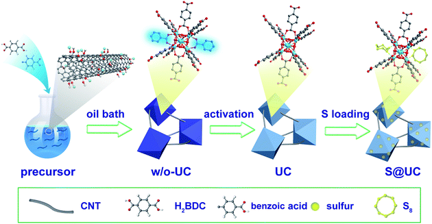
A typical preparation procedure of UC composites as a sulfur host is illustrated in Fig. 1. On one hand, according to the electrostatic attraction, the electropositive Zr4+ of zirconium tetrachloride is easily attracted and adsorbed to the strongly electronegative oxygen functional groups from the surface of acid-treated CNTs, which contributes to intensive nucleation of UiO-66 on the CNTs. These small crystal nuclei anchored on the surface of the CNTs will grow and form UiO-66 nanocrystals by penetrating the CNTs, which can finally establish an outstanding 3D conductive network. On the other hand, a building unit of ideal UiO-66 is composed of an inner Zr6O4(OH)4 core and 12 BDC linkers with full coordination, which cannot provide any available Lewis acid sites to anchor the LiPSs.47,62 Some studies have pointed out that acidic reagents as modulators can compete with H2BDC to coordinate Zr4+ to increase the number of active sites.63–65 In this paper, a quantity of benzoic acid as an additional ligand is used to forcefully trigger competitive coordination. After a thermal activation treatment, many coordination sites of the Zr4+ are exposed by eliminating unstructured benzoic acid linkers. These coordination defects may afford adequate active sites to immobilize polysulfides. We set up three DMF solutions with different CNT concentrations (2 mg mL−1, 3 mg mL−1 and 5 mg mL−1, respectively) to obtain the best balance between conductivity and LiPS entrapment in the UC composites. The resulting product series are correspondingly denoted UC-2, UC-3 and UC-5, with a CNT content of ∼22.8%, 34.3% and 55.9%, respectively. Sulfur impregnation into the as-synthesized UC composites was carried out through a combination of a facile immersion method and a traditional melt-diffusion process, where sulfur powder, with a large particle size, is dissociated into uniform nanosized particles in CS2 solvent and then more easily infiltrates the pores of UiO-66 with liquid sulfur at 155 °C. The desired S@UC hybrid series was finally obtained.The morphological features of the as-prepared products were investigated. Fig. S1a and b† show aggregates of small and intergrown UiO-66 particles (80–200 nm). As seen from the SEM images of UC-3 (Fig. 2a and S2a–c†), firstly, the octahedral UiO-66 nanocrystals with a narrow size range of ∼300–500 nm were synthesized, suggesting that benzoic acid participates in the coordination between Zr4+ and H2BDC ligands and, as the moderator, may suppress fast nucleation of UiO-66 grains. Furthermore, the TEM images (Fig. 2b and c and S2c, d†) clearly show that long CNTs are not only inserted into all of the UiO-66 nanoparticles, but also connect these particles. UC-2 and UC-5 (Fig. S1c–f†) show similar features to UC-3 in structural morphology, indicating the successful implantation of the conductive network into the UiO-66 octahedrons. Fig. 2d shows that the morphological uniformity of the UC-3 is well preserved after the sulfur encapsulation process in the S@UC-3 hybrid. Successful encapsulation of sulfur into the cavities of the MOF architecture is intuitively confirmed by TEM analysis (Fig. 2e and f), and no obvious sulfur tracks exist on the surface of the UC-3 particles. To further probe the distribution of sulfur in the UC series, energy dispersive X-ray spectroscopy (EDS) was performed on S@UC-3 particles as a representative of the S@UC hybrids. The sulfur element mapping (in Fig. 2g) clearly shows that most sulfur uniformly distributes inside the MOF particles and small amounts of sulfur also exist in the CNTs, which is in good accordance with the carbon mapping and further confirmed by the line-scanning EDS measurements shown in Fig. 2h.
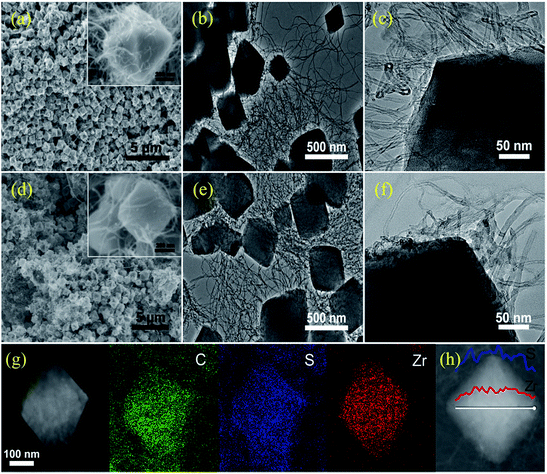 | ||
| Fig. 2 SEM and TEM images of as-prepared (a)–(c) UC-3 and (d)–(f) S@UC-3; (g) and (h) elemental mapping and linear EDX element distributions of zirconium and sulfur of S@UC-3 hybrids. | ||
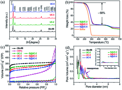
Fig. 3a shows the XRD patterns of pristine UiO-66 and the UC series. The UC series displays the same characteristic peaks from 5° to 35° as UiO-66, indicating that the introduction of CNTs and benzoic acid and a subsequent activation do not destroy the crystal structure of the UiO-66 framework. Strong orthorhombic sulfur peaks (PDF#83-2283) in the XRD patterns of the S@UC series (Fig. S3†) reflect residual sulfur on the surface of the UC architectures after sulfur encapsulation. The weight ratio of sulfur in the three S@UC hybrids is ∼68 wt% from the TGA curves in Fig. 3b. As shown in Fig. 3c, UiO-66 and the UC series display very similar N2 adsorption/desorption behavior, in which a very strong absorption at low pressure (<0.01 at P/P0) is observed, revealing an abundant microporous nature. With increasing CNT content, a rise at high relative pressure (>0.7 at P/P0) appears in the isotherms of UC-3 and UC-5 due to their mesoporous structures. The pore size distribution derived from NLDFT calculations clearly shows abundant microporosity and emerging mesoporosity (Fig. 3d). UiO-66 exhibits a high BET surface area of 1157 m2 g−1 and a large pore volume of 0.43 cm3 g−1. After adding CNTs with a low surface area of 278 m2 g−1, the UC series still maintains the high specific surface area properties of UiO-66 frameworks, viz. 976 m2 g−1 (UC-2), 863 m2 g−1 (UC-3) and 738 m2 g−1 (UC-5), respectively. Besides, their pore volume and average pore sizes are enlarged (Table S1†). After sulfur encapsulation, the specific surface areas of the UC series sharply decrease to 17.13 m2 g−1, 15.36 m2 g−1 and 6.62 m2 g−1, respectively, demonstrating a successful filling of sulfur into the cavities of the UC series.
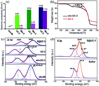
High electronic conductivity, excellent structural stability and strong polysulfide adsorption are three crucial factors for assessing advanced sulfur hosting materials for Li–S batteries. The electronic insulation of MOFs intrinsically defines a very low conductivity for UiO-66 (generally <10−10 S cm−1).51 Benefiting from construction of the 3D conductive CNT networks, the UC series exhibited dramatically improved conductivity at room temperature (UC-2: 8.69 S cm−1, UC-3: 12.54 S cm−1 and UC-3: 13.68 S cm−1), far above that of pristine UiO-66 and the homologous mixtures of UiO-66 and CNTs with an equivalent ratio (denoted mix-2, mix-3 and mix-5, respectively), as shown in Fig. 4a. Thermogravimetric analysis (TGA) was performed to obtain traces of UC-3 both with and without activation (denoted w/o-UC-3) (Fig. 4b). Very high thermal stability was exhibited until a sharp degradation at ∼540 °C due to abundant linker connections and a high degree of Zr–O coordination. A moderate weight loss of ∼7.6 wt% between 200 °C and 350 °C was observed in the trace of w/o-UC-3. Apparently, the mass loss from the internal dehydroxylation of the Zr6O4(OH)4 cluster (loss of 2H2O molecules) is negligible for a superstructural UiO-66 unit,47 indicating that additional linker vacancies might be generated by the removal of unstructural benzoic acid after activation.
X-ray photoelectron spectroscopy (XPS) measurements were performed to validate our reasoning on the linker-missing defects. In Fig. 4c, the Zr 3d spectra is split into two typical peaks corresponding to 3d3/2 and 3d5/2. For w/o-UC-3, a small chemical shift, compared with that of pristine UiO-66 (ΔE1 = 0.19 eV), in Zr 3d5/2 towards higher energy levels is observed due to the difference between benzoic acid and H2BDC ligands coordinating with the Zr4+. After activation, the Zr 3d5/2 peak remarkably shifts positively to the higher level of 183.76 eV (ΔE2 = 0.60 eV), reflecting the weakness of additional electron-pairs around the coordinated orbitals of Zr4+. Encapsulation of sulfur into UC-3 triggers a larger Zr 3d5/2 level shift (ΔE2 = 1.22 eV) from 183.76 eV to 182.54 eV, indicating an abundant supply of coordinated electron-pairs from electron-rich sulfur. To verify that the coordination vacancies of Zr4+ result from removing benzoic acid linkers, the C 1s and O 1s spectra were quantitatively analyzed (in Fig. S4 and Table S2†). In its C 1s spectrum, pristine UiO-66 shows two peaks assigned to the C–C (284.79 eV) bonds of the benzene ring and the terminal O![[double bond, length as m-dash]](https://www.rsc.org/images/entities/char_e001.gif) C–O (289.80 eV) from the BDC linkers. Two additional peaks at 285.62 eV and 286.74 eV from the oxygen functional groups (C–O and C
C–O (289.80 eV) from the BDC linkers. Two additional peaks at 285.62 eV and 286.74 eV from the oxygen functional groups (C–O and C![[double bond, length as m-dash]](https://www.rsc.org/images/entities/char_e001.gif) O) of CNTs appear in w/o-UC-3 almost without any change after activation in UC-3, owing to negligible contributions of CNTs to the weight loss in the activation process. Additionally, an obvious content decrease from 29.09% to 24.49% of C–O–Zr bonds (532.00 eV) was determined from the O 1s spectra of w/o-UC-3 and UC-3. These analytical results definitely show that the coordination vacancies are caused by removing benzoic acid linkers. For the S 2p spectra (in Fig. 4d), an obvious chemical peak at a lower energy level (163.37 eV) is observed in the S@UC-3 compared with that of elemental sulfur, indicating a strong chemical interaction between sulfur and the Zr4+ in UC-3.
O) of CNTs appear in w/o-UC-3 almost without any change after activation in UC-3, owing to negligible contributions of CNTs to the weight loss in the activation process. Additionally, an obvious content decrease from 29.09% to 24.49% of C–O–Zr bonds (532.00 eV) was determined from the O 1s spectra of w/o-UC-3 and UC-3. These analytical results definitely show that the coordination vacancies are caused by removing benzoic acid linkers. For the S 2p spectra (in Fig. 4d), an obvious chemical peak at a lower energy level (163.37 eV) is observed in the S@UC-3 compared with that of elemental sulfur, indicating a strong chemical interaction between sulfur and the Zr4+ in UC-3.
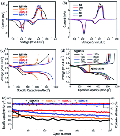
Electrochemical tests were carried out to evaluate the merits of using the UC series in Li–S batteries. Fig. 5a shows the cyclic voltammogram (CV) curves of the S@UC series and S@CNTs in the voltage range of 1.7–2.8 V. For the three S@UC hybrids, typical CV features of sulfur cathodes were observed, with two characteristic peaks in the reduction process attributed to the transformation of ring-shaped S8 to long-chain Li2Sx (4 < x < 8) and a further reduction to lower-order Li2S2/Li2S and two oxidation peaks ascribed to the conversion of Li2S2/Li2S to higher-order Li2Sn (n > 2) and the ultimate formation of sulfur. For the S@CNTs hybrid, excess filling of sulfur into CNTs seriously suppress the electrochemistry of the electrode, leading to the lower reduction and higher oxidation potentials of S@CNTs than those of the S@UC series. Noticeably, from the 2nd to the 5th cycle of the S@UC-3 cathode, the almost overlapping curves reveal an effective suppression of the electrochemical polarization by the UC series, as shown in Fig. 5b. The representative galvanostatic charge–discharge profiles of S@UC cathodes between 1.7 and 2.8 V at 0.5 A g−1 are shown in Fig. 5c. All cathodes exhibit two typical discharging plateaus (∼2.3 V and ∼2.0 V vs. Li/Li+) corresponding to the multi-step reduction from sulfur to Li2S during the discharging process. Fig. S5† and 5d show several representative charge–discharge profiles of the three S@UC hybrids and the S@CNTs hybrid at 0.5 A g−1. The S@UC hybrids exhibit obvious shrinkage (ΔE ≈ 0.29 eV) of both the upper and lower discharge plateaus compared to that of the S@CNTs hybrid (ΔE > 0.5 eV), resulting from the effective curbing of the loss of active material and relieving of the aggregation of insulating Li2S2/Li2S on the surface of the electrodes. The cycling performances of the S@UC and S@CNTs hybrids at 0.5 A g−1 are displayed in Fig. 5e, indicating an initial specific capacity of 691 mA h g−1 (S@UC-2), 925 mA h g−1 (S@UC-3) and 942 mA h g−1 (S@UC-5) and a capacity retention of 493 mA h g−1, 765 mA h g−1 and 600 mA h g−1 after 300 cycles, respectively. Undoubtedly, the S@CNTs electrode shows fast capacity recession with a serious fading rate of 0.180% per cycle. After undergoing fast capacity fading in the first several cycles, S@UC-2 and S@UC-3 displayed a very stable cycling performance with a capacity decay of only 0.068% and 0.028%, respectively, per cycle after the 5th cycle. However, the capacity of S@UC-5 still declined at a fast rate of 0.108%, resulting from the over-dose addition of nonpolar CNTs degenerating the chemisorption of LiPSs on UC-5. Fig. S6a† exhibits a clean separator without distinct traces of the dissolved LiPSs, implying an effective restriction of LiPSs in the S@UC-3 cathode. Meanwhile for S@CNTs, orange LiPSs exist over a large area on the separator, as shown in Fig. S6b.† More importantly, almost no variation of the UC-3 composite compared with the pristine state was clearly shown in the SEM images after 300 cycles (Fig. S6c–h†), indicating the excellent mechanical stability of the UC-3 architecture for withstanding large volume deformation during cycling processes. Considering the terrible conductivity of UiO-66, the cycling performances of S@UiO-66, S@CNTs and S@UC-3 electrodes were measured at a low current density of 0.1 A g−1 to rightly determine the enhanced chemisorption of polysulfides, as shown in Fig. S7.† S@UC-3 delivered a high initial capacity of 1045 mA h g−1 based on that of S@UiO-66 (670 mA h g−1), and still maintained a high retention of 897 mA h g−1 after 100 cycles, showing a lower decay rate of 0.14% per cycle than those of S@CNTs (0.35% per cycle) and S@UiO-66 (0.30% per cycle).
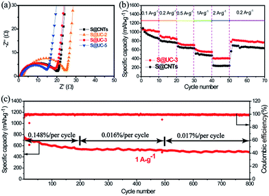
Electrochemical impedance spectroscopy (EIS) (Fig. 6a) shows an internal resistance order of S@UC-2 > S@CNTs > S@UC-3 > S@UC-5, supporting the capacity performance comparison. Rate performance was tested in the S@UC-3 hybrid at various current densities from 0.1 A g−1 to 2 A g−1 (Fig. 6b), delivering reversible capacities of 1058 mA h g−1, 915 mA h g−1, 752 mA h g−1 and 612 mA h g−1 at current densities of 0.1 A g−1, 0.2 A g−1, 0.5 A g−1 and 1 A g−1, respectively. Even increasing further to 2 A g−1, a high capacity of 411 mA h g−1 can be still retained. When current density is reduced abruptly back to 0.2 A g−1, S@UC-3 can recover back to 857 mA h g−1, most of the original capacity. Conversely, S@CNTs shows capacity instability at a low current density of 0.1 A g−1 and a sharp capacity drop between 1 A g−1 and 2 A g−1.
Longer cycling has been achieved at a high current density of 1 A g−1 using the S@UC-3 hybrid as the cathode (Fig. 6c), showing a high initial capacity of 764 mA h g−1 and very low fading rate of 0.07% per cycle after 800 cycles. In the first 200 cycles, the cell displays deterioration of the capacity with a decay rate of 0.148% per cycle, which may result from the irreversible loss of sulfur outside the UiO-66 framework during cycling. However, wonderful cycling stability with a low fading rate of 0.016% is obtained over the next 300 cycles due to the strong LiPS trapping effect. The S@UC-3 cathode still keeps a capacity decay rate as low as 0.017% per cycle over the last 300 cycles, which may owe more to the good mechanical performance of the UC architectures.
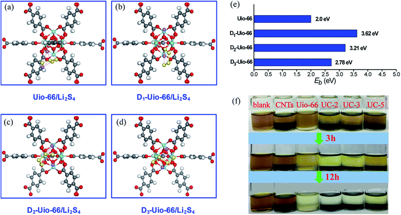
In order to further understand and confirm the role of coordination defects in trapping LiPSs, first principles calculations based on density functional theory (DFT) were performed. We set up models between several groups of UiO-66 with zero (intact UiO-66, in Fig. S8†), one, two and three linker-missing defects (denoted Dn-UiO-66, n = 1, 2 and 3, in Fig. S9†) and Li2S4 (as a representative LiPS) to confirm the role of the coordination defects in trapping LiPSs, as shown in Fig. 7a–d. For pristine UiO-66, the inner cluster is occupied by 12 linkers with full coordination, and thus has no active site. Moreover, fully coordinated linkers form very closely-packed obstacles to the approach of Li2S4 molecules to the core. The linker vacancies not only create the active sites, but also effectively reduce the number of obstacles and enlarge the inner cavities.63,64 Thus, Li2S4 molecules easily reach and interact with the inner cluster. As expected, the computational results (Fig. 7e) show a stronger affinity of Dn-UiO-66 than intact UiO-66 to the Li2S4 molecule. However, increasing linker-missing defects cause a counteracting effect on the adsorption of Li2S4, leading to weakening binding energy. Surprisingly, intact UiO-66 still exhibits a decent binding energy (∼2.0 eV) for Li2S4, which is mainly attributed to the strong attraction of abundant electrons from the benzene ring of the linkers to the Li cations of Li2S4. Moreover, a static Li2S6 adsorption test was conducted to investigate the adsorption capacity of the UC series for LiPSs. Fig. 7f clearly shows the changes in Li2S6 absorption in the UC series and control groups of UiO-66 and CNTs, which reveals the adsorption capacity order of the samples, UC-2 = UC-3 > UC-5 = UiO-66 ≫ CNTs, and thus demonstrates a significantly stronger affinity of Li2S6 molecules with the UC series than with pristine UiO-66 or nonpolar carbon materials. Hence, the coordination defects distinctly promote the chemisorption kinetics of the UC composites for Li2S6. However, it is notable that an excess content of nonpolar CNTs would badly weaken the adsorption capacity of the UC composite (like UC-5).
Generally, the multi-functionalized UC composite as a sulfur host has achieved dramatically improved capacity and cycling performances. In particular, the cycling stability of the S@UC-3 electrode surpasses most MOF-based sulfur electrodes (Table S3†) and representative MOF-derived carbon electrodes (Table S4†), and can be competitive with typical metallide electrodes with strong chemisorption for LiPSs (Table S5†). Furthermore, DFT calculations adequately reveal the mechanism of LiPS adsorption onto the linker-defective UiO-66. Despite the computational result that the intensive loss of several adjacent linkers in a UiO-66 unit would cause a weakening of the entrapment of LiPSs, it is hard for this to happen in the synthesis of these materials considering the stability of MOF coordination. Due to the much greater ligand connection, it is entirely possible that one linker or two nonadjacent linkers were artificially removed from a UiO-66 unit without compromising the structural stability, which substantially increases the amount of effective active sites.
Conclusion
In this paper, the competitive coordination principle is introduced for the first time in Li–S batteries to design and fabricate a class of linker-missing UiO-66/CNT (UC) composites as the sulfur hosts. Meanwhile, we also achieved a combination of high electronic conductivity, excellent structural stability, and strong chemisorption via a facile synthesis. Finally, the S@UC-3 hybrid, as the best optimization, achieved significantly improved electrochemical dynamics of the sulfur reaction and excellent cycling stability. Most strikingly, theoretical studies unveil a strong chemical affinity between UiO-66 with linker-missing defects and polysulfides, which fundamentally demonstrates the electrochemical mechanism and validly supports the experimental cell results.Conflicts of interest
The authors declare no conflict of interest.Acknowledgements
This work was supported by the National Key R&D Program of China (No. 2016YFB0100400).Notes and references
- S. Evers and L. F. Nazar, Acc. Chem. Res., 2013, 46, 1135–1143 CrossRef PubMed.
- Y. Yang, G. Y. Zheng and Y. Cui, Chem. Soc. Rev., 2013, 42, 3018–3032 RSC.
- B. Ding, C. Yuan, L. Shen, G. Xu, P. Nie and X. Zhang, Chem.–Eur. J., 2013, 19, 1013–1019 CrossRef PubMed.
- Z. W. Seh, Y. Sun, Q. Zhang and Y. Cui, Chem. Soc. Rev., 2016, 45, 5605–5634 RSC.
- J. Zhang, H. Huang, J. Bae, S. H. Chung, W. Zhang, A. Manthiram and G. Yu, Small Methods, 2017, 2, 1700279 CrossRef.
- P. G. Bruce, S. A. Freunberger, L. J. Hardwick and J. M. Tarascon, Nat. Mater., 2011, 11, 19–29 CrossRef PubMed.
- Y.-X. Yin, S. Xin, Y.-G. Guo and L.-J. Wan, Angew. Chem., Int. Ed., 2013, 52, 13186–13200 CrossRef PubMed.
- L. Ma, K. E. Hendrickson, S. Wei and L. A. Archer, Nano Today, 2015, 10, 315–338 CrossRef.
- M. A. Pope and I. A. Aksay, Adv. Energy Mater., 2015, 5, 1500124 CrossRef.
- Q. Pang, X. Liang, C. Y. Kwok and L. F. Nazar, Nat. Energy, 2016, 1, 16132 CrossRef.
- S. Rehman, K. Khan, Y. Zhao and Y. Hou, J. Mater. Chem. A, 2017, 5, 3014–3038 Search PubMed.
- X. Liu, J.-Q. Huang, Q. Zhang and L. Mai, Adv. Mater., 2017, 29, 1601759 CrossRef PubMed.
- Y. Zhao, W. Wu, J. Li, Z. Xu and L. Guan, Adv. Mater., 2014, 26, 5113–5118 CrossRef PubMed.
- M. Yu, R. Li, M. Wu and G. Shi, Energy Storage Materials, 2015, 1, 51–73 CrossRef.
- J. Schuster, G. He, B. Mandlmeier, T. Yim, K. T. Lee, T. Bein and L. F. Nazar, Angew. Chem., 2012, 124, 3651–3655 CrossRef.
- H.-J. Peng, J.-Q. Huang, M.-Q. Zhao, Q. Zhang, X.-B. Cheng, X.-Y. Liu, W.-Z. Qian and F. Wei, Adv. Funct. Mater., 2014, 24, 2772–2781 CrossRef.
- Q. Li, Z. Zhang, K. Zhang, J. Fang, Y. Lai and J. Li, J. Power Sources, 2014, 256, 137–144 CrossRef.
- J. Zhang, J. Xiang, Z. Dong, Y. Liu, Y. Wu, C. Xu and G. Du, Electrochim. Acta, 2014, 116, 146–151 CrossRef.
- J. Zhang, Z. Dong, X. Wang, X. Zhao, J. Tu, Q. Su and G. Du, J. Power Sources, 2014, 270, 1–8 CrossRef.
- C. Xu, Y. Wu, X. Zhao, X. Wang, G. Du, J. Zhang and J. Tu, J. Power Sources, 2015, 275, 22–25 CrossRef.
- Q. Pang, X. Liang, C. Y. Kwok and L. F. Nazar, J. Electrochem. Soc., 2015, 162, A2567–A2576 CrossRef.
- T. Chen, B. Cheng, G. Zhu, R. Chen, Y. Hu, L. Ma, H. Lv, Y. Wang, J. Liang, Z. Tie, Z. Jin and J. Liu, Nano Lett., 2017, 17, 437–444 CrossRef PubMed.
- Z. Wei Seh, W. Li, J. J. Cha, G. Zheng, Y. Yang, M. T. McDowell, P.-C. Hsu and Y. Cui, Nat. Commun., 2013, 4, 1331 CrossRef PubMed.
- X. Liang, C. Y. Kwok, F. Lodi-Marzano, Q. Pang, M. Cuisinier, H. Huang, C. J. Hart, D. Houtarde, K. Kaup, H. Sommer, T. Brezesinski, J. Janek and L. F. Nazar, Adv. Energy Mater., 2016, 6, 1501636 CrossRef.
- J. Zhang, Y. Shi, Y. Ding, W. Zhang and G. Yu, Nano Lett., 2016, 16, 7276–7281 CrossRef PubMed.
- L. Ma, R. Chen, G. Zhu, Y. Hu, Y. Wang, T. Chen, J. Liu and Z. Jin, ACS Nano, 2017, 11, 7274–7283 CrossRef PubMed.
- Z. W. Seh, J. H. Yu, W. Li, P.-C. Hsu, H. Wang, Y. Sun, H. Yao, Q. Zhang and Y. Cui, Nat. Commun., 2014, 5, 5017 CrossRef PubMed.
- Z. Yuan, H.-J. Peng, T.-Z. Hou, J.-Q. Huang, C.-M. Chen, D.-W. Wang, X.-B. Cheng, F. Wei and Q. Zhang, Nano Lett., 2016, 16, 519–527 CrossRef PubMed.
- Q. Pang, D. Kundu and L. F. Nazar, Mater. Horiz., 2016, 3, 130–136 RSC.
- T. Lei, W. Chen, J. Huang, C. Yan, H. Sun, C. Wang, W. Zhang, Y. Li and J. Xiong, Adv. Energy Mater., 2017, 7, 1601843 CrossRef.
- C. Ye, L. Zhang, C. Guo, D. Li, A. Vasileff, H. Wang and S.-Z. Qiao, Adv. Funct. Mater., 2017, 27, 1702524 CrossRef.
- Z. Cui, C. Zu, W. Zhou, A. Manthiram and J. B. Goodenough, Adv. Mater., 2016, 28, 6926–6931 CrossRef PubMed.
- Z. Sun, J. Zhang, L. Yin, G. Hu, R. Fang, H.-M. Cheng and F. Li, Nat. Commun., 2017, 8, 14627 CrossRef PubMed.
- Q. Pang, X. Liang, C. Y. Kwok, J. Kulisch and L. F. Nazar, Adv. Energy Mater., 2017, 7, 1601630 CrossRef.
- D.-R. Deng, F. Xue, Y.-J. Jia, J.-C. Ye, C.-D. Bai, M.-S. Zheng and Q.-F. Dong, ACS Nano, 2017, 11, 6031–6039 CrossRef PubMed.
- W. Li, Q. Zhang, G. Zheng, Z. W. Seh, H. Yao and Y. Cui, Nano Lett., 2013, 13, 5534–5540 CrossRef PubMed.
- J. Shao, X. Li, L. Zhang, Q. Qu and H. Zheng, Nanoscale, 2013, 5, 1460–1464 RSC.
- X. Liang, A. Garsuch and L. F. Nazar, Angew. Chem., Int. Ed., 2015, 54, 3907–3911 CrossRef PubMed.
- X. Liang, Y. Rangom, C. Y. Kwok, Q. Pang and L. F. Nazar, Adv. Mater., 2017, 29, 1603040 CrossRef PubMed.
- Z. Wang, X. Li, Y. Cui, Y. Yang, H. Pan, Z. Wang, C. Wu, B. Chen and G. Qian, Cryst. Growth Des., 2013, 13, 5116–5120 Search PubMed.
- J. Zheng, J. Tian, D. Wu, M. Gu, W. Xu, C. Wang, F. Gao, M. H. Engelhard, J.-G. Zhang, J. Liu and J. Xiao, Nano Lett., 2014, 14, 2345–2352 CrossRef PubMed.
- J. Zhou, R. Li, X. Fan, Y. Chen, R. Han, W. Li, J. Zheng, B. Wang and X. Li, Energy Environ. Sci., 2014, 7, 2715–2724 Search PubMed.
- Z. Wang, B. Wang, Y. Yang, Y. Cui, Z. Wang, B. Chen and G. Qian, ACS Appl. Mater. Interfaces, 2015, 7, 20999–21004 Search PubMed.
- H. Park and D. J. Siegel, Chem. Mater., 2017, 29, 4932–4939 CrossRef.
- Y. Hou, H. Mao and L. Xu, Nano Res., 2017, 10, 344–353 CrossRef.
- X. Cao, C. Tan, M. Sindoro and H. Zhang, Chem. Soc. Rev., 2017, 46, 2660–2677 RSC.
- J. H. Cavka, S. Jakobsen, U. Olsbye, N. Guillou, C. Lamberti, S. Bordiga and K. P. Lillerud, J. Am. Chem. Soc., 2008, 130, 13850–13851 CrossRef PubMed.
- H. Wu, T. Yildirim and W. Zhou, J. Phys. Chem. Lett., 2013, 4, 925–930 CrossRef PubMed.
- Q. Zhao, W. Yuan, J. Liang and J. Li, Int. J. Hydrogen Energy, 2013, 38, 13104–13109 CrossRef.
- W. Bao, Z. Zhang, Y. Qu, C. Zhou, X. Wang and J. Li, J. Alloys Compd., 2014, 582, 334–340 CrossRef.
- K. M. Choi, H. M. Jeong, J. H. Park, Y.-B. Zhang, J. K. Kang and O. M. Yaghi, ACS Nano, 2014, 8, 7451–7457 CrossRef PubMed.
- Y. Mao, G. Li, Y. Guo, Z. Li, C. Liang, X. Peng and Z. Lin, Nat. Commun., 2017, 8, 14628 CrossRef PubMed.
- H. B. Wu, S. Wei, L. Zhang, R. Xu, H. H. Hng and X. W. Lou, Chem.–Eur. J., 2013, 19, 10804–10808 CrossRef PubMed.
- X. Yang, N. Yan, W. Zhou, H. Zhang, X. Li and H. Zhang, J. Mater. Chem. A, 2015, 3, 15314–15323 Search PubMed.
- S. Cai, X. Wang, M. Chen, J. Liu, Q. Lu and S. Wei, J. Electrochem. Soc., 2016, 163, A2922–A2929 CrossRef.
- Z. Li, C. Li, X. Ge, J. Ma, Z. Zhang, Q. Li, C. Wang and L. Yin, Nano Energy, 2016, 23, 15–26 CrossRef.
- G. Kresse and J. Hafner, Phys. Rev. B: Condens. Matter Mater. Phys., 1993, 47, 558–561 CrossRef.
- P. E. Blöchl, Phys. Rev. B: Condens. Matter Mater. Phys., 1994, 50, 17953–17979 CrossRef.
- J. P. Perdew, K. Burke and M. Ernzerhof, Phys. Rev. Lett., 1996, 77, 3865–3868 CrossRef PubMed.
- G. Kresse and D. Joubert, Phys. Rev. B: Condens. Matter Mater. Phys., 1999, 59, 1758–1775 CrossRef.
- J. Neugebauer and M. Scheffler, Phys. Rev. B: Condens. Matter Mater. Phys., 1992, 46, 16067–16080 CrossRef.
- H.-L. Jiang, D. Feng, T.-F. Liu, J.-R. Li and H.-C. Zhou, J. Am. Chem. Soc., 2012, 134, 14690–14693 CrossRef PubMed.
- F. Vermoortele, B. Bueken, G. Le Bars, B. Van de Voorde, M. Vandichel, K. Houthoofd, A. Vimont, M. Daturi, M. Waroquier, V. Van Speybroeck, C. Kirschhock and D. E. De Vos, J. Am. Chem. Soc., 2013, 135, 11465–11468 CrossRef PubMed.
- H. Wu, Y. S. Chua, V. Krungleviciute, M. Tyagi, P. Chen, T. Yildirim and W. Zhou, J. Am. Chem. Soc., 2013, 135, 10525–10532 CrossRef PubMed.
- S. Ling and B. Slater, Chem. Sci., 2016, 7, 4706–4712 RSC.
Footnote |
| † Electronic supplementary information (ESI) available. See DOI: 10.1039/c8ra02254b |
| This journal is © The Royal Society of Chemistry 2018 |

