
 Open Access Article
 This Open Access Article is licensed under a Creative Commons Attribution-Non Commercial 3.0 Unported Licence
In situ synthesis of molybdenum carbide/N-doped carbon hybrids as an efficient hydrogen-evolution electrocatalyst†
Jing Lia,
Chenmin Zhoua,
Jianshuai Mua,
En-Cui Yang*a and
Xiao-Jun Zhao *ab
*ab
aCollege of Chemistry, Key Laboratory of Inorganic-Organic Hybrid Functional Material Chemistry, Ministry of Education, Tianjin Key Laboratory of Structure and Performance for Functional Molecules, Tianjin Normal University, Tianjin 300387, P. R. China. E-mail: encui_yang@163.com; xiaojun_zhao15@163.com; Fax: +86-22-23766556
bCollaborative Innovation Center of Chemical Science and Engineering, Tianjin, 300071, China
First published on 10th May 2018
Abstract
The development of non-precious metal based electrocatalysts for the hydrogen evolution reaction (HER) has received more and more attention over recent years owing to energy and environmental issues, and Mo based materials have been explored as a promising candidate. In this work, molybdenum carbide/N-doped carbon hybrids (Mo2C@NC) were synthesized facilely via one-step high-temperature pyrolysis by adjusting the mass ratio of urea and ammonium molybdate. The Mo2C@NC consisted of ultrasmall nanoparticles encapsulated by N-doped carbon, which had high specific surface area. They all exhibited efficient HER activity, and the Mo2C@NC with a mass ratio of 160 (Mo2C@NC-160) showed the best HER activity, with a low overpotential of 90 mV to reach 10 mA cm−2 and a small Tafel slope of 50 mV dec−1, which was one of the most active reported Mo2C-based electrocatalysts. The excellent HER activity of Mo2C@NC-160 was attributed to the following features: (1) the highly dispersed ultrasmall Mo2C nanoparticles, which exhibited high electrochemically active surface areas; (2) the synergistic effect of the N-doped carbon shell/matrix, which facilitated the electron transport.
Introduction
With the increase of traditional fossil fuel energy consumption and the associated environmental pollution, considerable efforts have been devoted to exploiting sustainable and clean energy sources to solve the intractable energy and environmental problem. Hydrogen, as a key energy carrier, has been regarded as one of the most promising alternatives to traditional fossil fuels.1 Electrochemical water splitting driven by green energy resources has been considered as a promising approach to produce hydrogen fuel.2 Water splitting requires efficient electrocatalysts to promote the hydrogen evolution reaction (HER) at low overpotentials. It is well known that platinum (Pt) is the most active HER electrocatalyst,3 however its high cost and low abundance limit its large-scale application. Therefore, numerous efforts have been made to develop precious metal-free electrocatalysts with high performance and low cost for practical large-scale hydrogen production.4,5So far, several non-noble metal-based materials, including transition-metal carbides,6 nitrides,7 phosphides8 and chalcogenides9 have received more and more attention as alternative HER electrocatalysts. Among these catalysts, transition-metal carbides have recently received a great amount of attention because of their similar electronic structure to that of Pt, good corrosion resistance and stability.10 Particularly, one such carbide, molybdenum carbide (Mo2C) is one of the most potential transition-metal carbides due to its efficient catalytic activity, good conductivity, high melting point and low cost.11–15 Recently, constructing various Mo2C nanomaterials with particular morphology such as nanowires,16nanosheets17 and nanotubes18 enhanced their HER performance owing to exposure of more active sites. Mo2C nanomaterials are generally obtained by the high-temperature pyrolysis of precursors containing molybdenum and carbon/organic compounds.19,20 However the high-temperature pyrolysis may lead to inevitable aggregation and/or excessive growth, which results in low specific surface area and subsequently low density of catalytic active sites. Therefore, it is still challenging to prepare Mo2C with well-defined nanostructures and high specific surface area to expose more catalytical active sites for enhancing HER performance. Mo2C nanoparticles has been synthesized by the ‘urea glass’ route with MoCl5 and urea as precursor, but exhibited low specific surface area.19 And some works reported that using ammonium molybdate and some organic compounds (for example glucose and dicyanamide) as Mo and carbon sources produced the Mo2C nanomaterials with high specific surface area.21,22 Therefore, changing the precursor of Mo and carbon sources might a convenient procedure for constructing Mo2C nanomaterials with new nanostructures and high specific surface area in order to enhance their HER performance.
Herein, we utilized urea and ammonium molybdatetetrahydrate as carbon and Mo sources to prepare Mo2C@NC via one-step procedure by changing the urea/metal ratio. The obtained Mo2C@NC had high specific surface areas, exhibited excellent electrocatalytic HER activity with a low overpotential of 90 mV to reach 10 mA cm−2 and a small Tafel slope of 50 mV dec−1, which was one of the most active reported Mo2C-based electrocatalysts.
Material and methods
Materials
Ammonium molybdatetetrahydrate, urea and potassium hydroxide were purchased from HeownsBiochem Technologies (Alpharetta GA, USA). Nafion solution (5% in a mixture of lower aliphatic alcohols and water) and Pt/C (20% Pt on Vulcan XC72) were purchased from Sigma-Aldrich (St. Louis, USA).Preparation of Mo2C@NC
Urea and ammonium molybdatetetrahydrate (20 mg) with different mass ratios (R (urea/ammonium molybdatetetrahydrate) = 80, 160, 240 and 320) were dissolved into 15 mL water, evaporated in a constant temperature bath at 100 °C under stirring, and then dried into white precursors. The precursors were placed on quartz boats with a cover, and transferred to a quartz tube furnace. They were heated at 400 °C with a ramp of 2 °C min−1 in N2 atmosphere, and further 800 °C min−1 for 6 h with a ramp of 5 °C min−1 to obtain black products. The products were named as Mo2C@NC-80, Mo2C@NC-160, Mo2C@NC-240 and Mo2C@NC-320, respectively.Materials characterization
X-ray powder diffraction (XRD) patterns were measured by a D8 ADVANCE X-ray diffractometer (Bruker, Germany) with Cu Kα radiation. The C content was measured by vario EL cube elemental analysis system (Elementar, Germany). The morphologies of products and EDX spectra were performed using a Nova Nano SEM 230 scanning electron microscope (FEI, USA) and a Tecnai G2 F20 transmission electron microscope (FEI, USA). X-ray photoelectron spectroscopy (XPS) was obtained by an AXIS Ultra DLD X-ray photoelectron spectroscopy (Shimadzu, Japan). N2 adsorption–desorption isotherms were measured by an ASAP 2020 Physisorption Analyzer (Micromeritics, USA), and the specific surface areas were calculated by the Brunauer–Emmett–Teller (BET) method.Electrochemical measurements
The electrocatalyst was (4 mg) dispersed in ethanol (0.475 mL) containing 5% Nafion solution (25 μL) under ultrasonic irradiation for 20 min to obtain a homogeneous ink. Then 8 μL ink was transferred onto a glassy carbon electrode (GCE) with 3 mm diameter and dried at 30 °C. For comparison, the same amount of Pt/C sample was dropped onto the GCE.Electrochemical experiments were performed by a three-electrode system with catalysts modified GCE as the working electrode, a graphite rod as the counter electrode and a saturated Ag/AgCl as the reference electrode at 25 °C. Potentials were referenced to a reversible hydrogen electrode: ERHE (V) = EAg/AgCl + 0.198 + 0.059 × pH. Prior to the experiments, the working electrode was cycled two hundreds times at a scan rate of 100 mV s−1. Linear sweep voltammetry (LSV) were recorded in 1 M KOH at a scan rate of 5 mV s−1 to obtain the polarization curves. The data were corrected for background current and iR losses. The Turn Over Frequency (TOF) values were calculated using equation: TOF = jSgeo/2Fn, by assuming every metal atom was involved in the catalytic reaction.23 Here, j (mA cm−2) was the measured current density at η = 90 mV. Sgeo was the surface area of glassy carbon (0.07065 cm2). The number 2 was the number of electrons per mole of H2. F was Faraday's constant (96![[thin space (1/6-em)]](https://www.rsc.org/images/entities/char_2009.gif) 485.3 C mol−1) and n was the moles of the metal atom on the electrode based on the loading mass and molecular weight of the coated catalysts. The electrochemically active surface areas (ECSA) of the electrocatalysts were calculated by the double-layer capacitor with the reported electrochemical method.21 The cyclic voltammograms (CVs) were performed with different rates from 20 to 100 mV s−1 in the range of 0.15–0.25 V (vs. RHE). The electrochemical impedance spectroscopy (EIS) measurements were carried out using an Autolab potentiostat (Eco Chmie, The Netherlands) in the frequency range from 100 KHz to 0.1 Hz. The EIS data were analyzed and fitted with the ZView software. The solution resistances (R) were measured by EIS, and calculated to be about 8 Ω, which was used for the iR correction. The stability was tested at a scan rate of 50 mV s−1 for 2000 cycles and by long-term chronoamperometry.
485.3 C mol−1) and n was the moles of the metal atom on the electrode based on the loading mass and molecular weight of the coated catalysts. The electrochemically active surface areas (ECSA) of the electrocatalysts were calculated by the double-layer capacitor with the reported electrochemical method.21 The cyclic voltammograms (CVs) were performed with different rates from 20 to 100 mV s−1 in the range of 0.15–0.25 V (vs. RHE). The electrochemical impedance spectroscopy (EIS) measurements were carried out using an Autolab potentiostat (Eco Chmie, The Netherlands) in the frequency range from 100 KHz to 0.1 Hz. The EIS data were analyzed and fitted with the ZView software. The solution resistances (R) were measured by EIS, and calculated to be about 8 Ω, which was used for the iR correction. The stability was tested at a scan rate of 50 mV s−1 for 2000 cycles and by long-term chronoamperometry.
Results and discussion
Characterization of Mo2C@NC
The synthesis of Mo2C@NC was achieved by simple thermal treatment of the inexpensive starting materials (urea and ammonium molybdatetetrahydrate) in N2 atmosphere. The synthesized products with different mass ratios of urea/ammonium molybdatetetrahydrate were confirmed by X-ray diffraction. At the mass ratio R = 80, Mo2C (JCPDS card no. 35-0787) with diffraction peaks of (100), (002), (101), (102), (110), (103) and (112) was obtained (Fig. 1).24 No other crystalline phases (for example, molybdenum nitride and MoOx) could be observed in the XRD patterns, indicating its purity. While, with a further increase to R = 160, 240 and 320, the diffraction peaks of the three Mo2C products decreased, and an evident broad peak around 26° corresponding to graphene (002) crystal planes was presented, showing the formation of amorphous carbon and the high content of carbon, compared with Mo2C@NC-80.18 To better know the elemental composition of Mo2C products, EDX analysis was measured. The EDX spectra showed the Mo2C products consisted of C, Mo, N and O elements, and the carbon content increased as the increase of urea amount. (Fig. S1†). The precise free carbon content of the different Mo2C products was calculated by the results of elemental analysis system (Table S1†), which verified the above XRD and EDX results. There was no carbon peak for Mo2C@NC-80, possibly due to the relatively low urea used for its synthesis, whereas high amount of urea could lead to poor crystallinity for Mo2C@NC-160, Mo2C@NC-240 and Mo2C@NC-320 products. During the first annealing at 400 °C, the pyrolysis of urea could result in g-C3N4 material, which had a stacked 2D lamellar structure similar to graphite.25,26 And during the second annealing, the pyrolysis g-C3N4 and formed molybdenum oxide from the first annealing led to the formation of graphitic carbon, because Mo species could promote the catalytic growth of carbon from the decomposed intermediates of g-C3N4.21 It was concluded that adjusting the mass ratios of urea/ammonium molybdatetetrahydrate would result in the formation of Mo2C@NC with different crystalline degree and carbon content. The different crystalline degree and carbon content of synthesized Mo2C@NC catalysts might affect their electrochemical HER performance. | ||
| Fig. 1 XRD patterns of different Mo2C@NC. | ||
The morphology of synthesized products was characterized by SEM and TEM. Mo2C@NC-80 had a mixture of nanoparticles and nanoplates (Fig. S2a and b†). At high amount of carbon precursors, the morphology of Mo2C@NC-160, Mo2C@NC-240 and Mo2C@NC-320 products exhibited loose and porous nanoflakes (Fig. S2c–h†). TEM images showed that the nanoflakes constructed by ultrasmall nanoparticles with an average size of about 2.3 nm (Fig. 2a and b). HRTEM images further corroborated that the ultrasmall Mo2C nanoparticles embedded within carbon matrix with several layers, although amorphous carbon dominated the carbon matrix around the Mo2C nanoparticles (Fig. 2c and d). The lattice spacing on the Mo2C nanoparticles was 0.24 nm, which corresponds to the (002) crystal planes of Mo2C phase. The carbon matrix should be resulted from decomposed g-C3N4 via the second annealing, accompanying the reduction of molybdenum oxide and the production of Mo2C. The elemental mapping (Fig. S3†) revealed that the C, Mo and N atoms were homogeneously distributed over the entire material, suggesting that the ultrasmall Mo2C nanocrystals were uniformly distributed within the N-doped carbon matrices. The ultrasmall size and uniform distribution of Mo2C nanoparticles might be ascribed to the confining effect of g-C3N4 lamellar structure produced from urea during the first annealing.
 | ||
| Fig. 2 (a and b) TEM and (c and d) HRTEM images of Mo2C@NC-160 nanomaterial. | ||
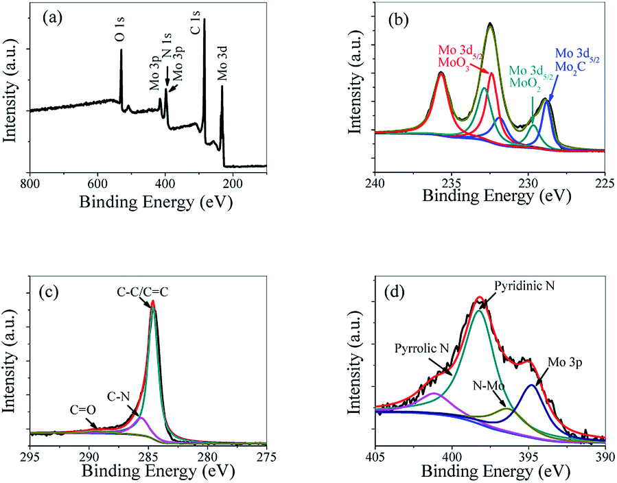
To confirm the chemical composition and valence states of Mo2C@NC, the XPS spectra were studied. The XPS survey spectrum of Mo2C@NC-160 indicated the existence of Mo, C, N and O elements (Fig. 3a). The Mo 3d XPS spectrum displayed three different oxidation states at 228.8, 229.7 and 232.4 eV, which could be ascribed to Mo 3d5/2 of Mo2C, MoO2 and MoO3, respectively (Fig. 3b).27 It has been reported that Mo2C was prone to oxidation at the surface when exposed to air.28 The C 1s peaks at 284.6, 285.6 and 289.4 eV could be attributed to the C atoms of C–C/C![[double bond, length as m-dash]](https://www.rsc.org/images/entities/char_e001.gif) C, C–N, and O–CO species, respectively (Fig. 3c).11,29 However, no carbidic peak (ca. 284.2 eV) was observed. This might be caused by the graphitic carbon on the surface, which covered the signal of the carbidic carbon in a similar region of binding energy. The N 1s XPS spectrum showed the predominant contribution from pyridinic N (398.2 eV) and some minor contribution from graphitic N (401.1 eV) (Fig. 3d).30 The peak at 396.4 eV was assigned to the N 1s signal related to N–Mo bonding.31 Therefore, the XPS analysis indicated that the successful incorporation of N into both the carbon matrix and Mo2C. Due to the lone electron pair in the plane of the carbon matrix and Mo2C, these species of doped N can withdraw electrons and active hydrogen, thus enhance the HER performance of Mo2C@NC.32
C, C–N, and O–CO species, respectively (Fig. 3c).11,29 However, no carbidic peak (ca. 284.2 eV) was observed. This might be caused by the graphitic carbon on the surface, which covered the signal of the carbidic carbon in a similar region of binding energy. The N 1s XPS spectrum showed the predominant contribution from pyridinic N (398.2 eV) and some minor contribution from graphitic N (401.1 eV) (Fig. 3d).30 The peak at 396.4 eV was assigned to the N 1s signal related to N–Mo bonding.31 Therefore, the XPS analysis indicated that the successful incorporation of N into both the carbon matrix and Mo2C. Due to the lone electron pair in the plane of the carbon matrix and Mo2C, these species of doped N can withdraw electrons and active hydrogen, thus enhance the HER performance of Mo2C@NC.32
 | ||
| Fig. 3 XPS survey spectra (a), Mo 3d (b), C 1s (c) and N 1s (d) spectra of Mo2C@NC-160 nanomaterial. | ||
The specific surface areas and pore size distributions of Mo2C@NC were determined by N2 adsorption/desorption isotherms. Based on the Brunauer–Emmett–Teller model, the specific surface areas of Mo2C@NC-80, Mo2C@NC-160, Mo2C@NC-240 and Mo2C@NC-320 were 70.8, 186.7, 230.9 and 240.2 m2 g−1, respectively (Fig. S4a and Table S1†). The specific surface areas were much higher than that of some reported Mo2C materials synthesized by other procedures, such as urea glass route19 or other carbon sources,21 illustrating that employing urea and ammonium molybdate as carbon and Mo precursors could produce the Mo2C with high surface area. The high specific surface areas of synthesized Mo2C@NC nanomaterials might enhance their HER performance. The pore size distributions of Mo2C@NC nanomaterials exhibited a mesopore structure (2–5 nm, Fig. S4b†). The large surface area of Mo2C@NC nanomaterials might expose more active sites by increasing contact area between the catalysts and electrolyte, and their porosity structures could facilitate transfer of reactants and products, which enhanced mass transport and thus might increase their HER efficiency.
HER catalytic performance of Mo2C@NC
The electrocatalytic performance of synthesized products for HER were studied in alkaline solution (1 M KOH) using a typical three-electrode system. For comparison, the HER performance of Pt/C (20 wt%) was also evaluated. The polarization curves recorded for each individual electrode were showed in Fig. 4a. The HER activity of Mo2C@NC followed the order: Mo2C@NC-160 > Mo2C@NC-80 > Mo2C@NC-240 > Mo2C@NC-320, and their HER performances were summarized in Table S1.† Mo2C@NC-160 exhibited excellent catalytic activity with a low overpotential of only 90 mV to reach a current density of 10 mA cm2, which was 34, 38 and 57 mV lower than those of Mo2C@NC-80, Mo2C@NC-240 and Mo2C@NC-320. To our best knowledge, the HER activity of Mo2C@NC-160 was superior to most reported Mo-based electrocatalysts (Table 1).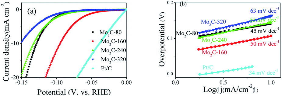 | ||
| Fig. 4 (a) Polarization curves and (b) Tafel plots of different Mo2C@NC electrocatalysts. | ||
| Catalyst | Catalyst amount (mg cm−2) | η10 (mV) | Tafel slope (mV dec−1) | Ref. |
|---|---|---|---|---|
| Mo2C@NC-160 | 0.90 | 90 | 50 | This work |
| Mo2C-GNR | — | 121 | 54 | 35 |
| Mo2C@2D-NPCs | 0.73 | 45 | 46 | 11 |
| m-Mo2C/G | 0.269 | 128 | 56 | 36 |
| Mo2C/NCF | 0.28 | 100 | 55 | 37 |
| MoC/Mo2C heteronanowires | 0.14 | 120 | 42 | 38 |
| MoxC-Ni@NCV | 1.1 | 126 | 93 | 30 |
| MoCx nano-octahedrons | 0.8 | 151 | 59 | 39 |
| β-Mo2C nanotubes | 0.75 | 112 | 55 | 18 |
To further investigate the HER reaction mechanism, the Tafel curves were fitted using the equation η = a + blog|j|, where a was the intercept, b was the Tafel slope and j was the current density (Fig. 4b). The Tafel slopes of Mo2C@NC-80 was calculated to be only 45 mV dec−1, which was lower than those of Mo2C@NC-160 (50 mV dec−1), Mo2C@NC-240 (55 mV dec−1), Mo2C@NC-320 (63 mV dec−1), and most of reported Mo2C-based electrocatalysts. It is well know that hydrogen evolution reaction involves two mechanistic pathways in alkaline condition as follows, which can be interpreted from the Tafel slopes.33,34
| Step I: H2O + e− + cat → H* − cat + OH− Volmer reaction (adsorption) |
| Step II: 2H* − cat → ↑H2 + 2 cat Tafel reaction (chemical desorption) |
| Step III: H* − cat + H2O + e− → ↑H2 + cat + OH− Heyrovsky reaction (electrochemical desorption) |
The first pathway involves step I and step II called Volmer–Tafel mechanism, and the second one involves step I and step III known as Volmer–Heyrovsky mechanism. In the Volmer–Tafel mechanism, if the Volmer reaction (adsorption of H* on the catalyst surface) is the rate-determining step, the Tafel slope should be 120 mV dec−1, while Tafel slope of 30 mV dec−1 implies Tafel reaction (chemical desorption) is the rate-determining step. However, in the Volmer–Heyrovsky mechanism, if the Heyrovsky reaction (electrochemical desorption) is the rate determining step, the Tafel slope should be around 40 mV dec−1. The Tafel slopes of Mo2C@NC ranged from 45 to 63 mV dec−1, indicating that the hydrogen evolution followed the Volmer–Heyrovsky mechanism, and Heyrovsky reaction (electrochemical desorption) was the rate-limiting step. As another important kinetic parameter for HER, the exchange current density (j0) represented the intrinsic activity of electrocatalysts. Based on the Tafel analysis, the j0 of Mo2C@NC-160 was determined to be 7.65 × 10⁻² mA cm−2, which was much higher than those of Mo2C@NC-80 (0.814 × 10⁻² mA cm−2), Mo2C@NC-240 (2.42 × 10⁻² mA cm−2) and Mo2C@NC-320 (2.74 × 10⁻² mA cm−2), revealing the exceptional H2 evolution efficiency of Mo2C@NC-160. In addition, the intrinsic catalytic activity of different Mo2C@NC electrocatalysts was also studied by the turnover frequency (TOF) for each active site to further accurately assess their HER activity, in which Mo2C@NC-160 showed the highest value of 11.7 × 10⁻³ s−1, much larger than that of Mo2C@NC-80 (0.806 × 10⁻³ s−1), Mo2C@NC-240 (1.16 × 10⁻³ s−1) and Mo2C@NC-320 (0.555 × 10⁻³ s−1) (Table S1†). The low η10, high j0 and high TOF value demonstrated that Mo2C@NC-160 exhibited the best HER performance.
To further investigate the HER kinetics of Mo2C@NC, electrochemical impedance studies were carried out at various overpotentials. The Nyquist and corresponding Bode plots of four Mo2C@NC electrocatalysts at overpotentials from 0 to 150 mV were obtained (Fig. S6,† 5 and 6). The Nyquist plots exhibited classical one-time constant behavior, and thus a simple electrical equivalent circuit was used to fit the experimental data, where Rs represents the resistance of the medium, Rct represents the charge transfer resistance between electrocatalysts and electrolyte, and CPE represents constant phase elements (Fig. 5).29 With the increase of overpotentials, the semicircle in the Nyquist plots decreased gradually, which indicated lower charge transfer resistance and better electron transfer ability at higher overpotentials. At 150 mV overpotential, the Rct value of Mo2C@NC-160 was calculated to be 28.5 Ohm, which was smaller than those of Mo2C@NC-80 (45.4 Ohm), Mo2C@NC-240 (71.6 Ohm) and Mo2C@NC-320 (90.1 Ohm). This indicated Mo2C@NC-160 had the best electron transfer ability. From the Bode plots, only one semicircle at low frequencies has been observed, which was related to the kinetics of the electrochemical HER (Fig. 6). In the Bode phase diagram, the semicircles exhibited potential dependency, and at higher applied potential the phase angle became lower and shifted towards higher frequencies (Fig. 6), which indicated lower resistance and faster reaction kinetics. The comparison of Bode plots for four Mo2C@NC electrocatalysts at 150 mV overpotential further demonstrated that Mo2C@NC-160 had excellent electron transfer ability and exhibited superior HER activity (Fig. S7†).
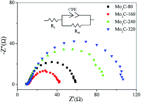 | ||
| Fig. 5 Comparison of Nyquist plots for different Mo2C@NC electrocatalysts at η = 150 mV. The insert showed the equivalent circuit. | ||
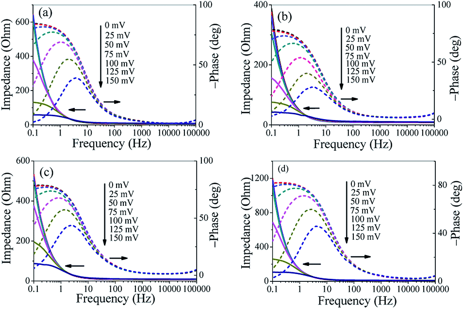 | ||
| Fig. 6 Bode plots of different Mo2C@NC electrocatalysts. (a) Mo2C@NC-80, (b) Mo2C@NC-160, (c) Mo2C@NC-240 and (d) Mo2C@NC-320. | ||
The efficient HER activity of Mo2C@NC-160 electrocatalyst was attributed to its high electron transfer ability as evidenced by the above EIS results. To further investigate the reason why Mo2C@NC-160 electrocatalyst exhibited higher HER activity than the other three Mo2C@NC electrocatalysts, their electrochemically active surface areas (ECSA) were estimated from the electrochemical double-layer capacitance (Cdl) of the catalytic surface, which was proportional to their effective electrode surface area.40 Therefore, the electrochemical surface areas of different Mo2C@NC could be compared with one another based on their Cdl values. The Cdl value could be determined by measuring the non-faradaic capacitive current associated with double-layer charging from the scan-rate dependence of cyclic voltammograms (CVs). All measured current in the non-faradaic potential region was assumed to be due to double-layer charging, and was equal to the product of the scan rate (v) and the electrochemical double-layer capacitance (Cdl), as given by eqn 1.
| ic = vCdl | (1) |
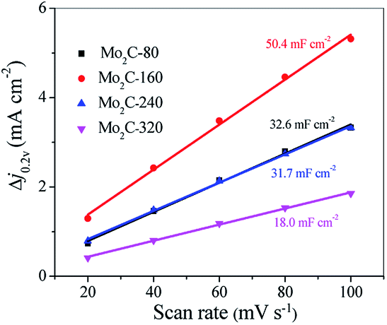
Thus, a plot of ic as a function of v yields a straight line with a slope equal to Cdl. The cyclic voltammetry (CV) of Mo2C@NC were obtained at different scan rates between 0.15 and 0.25 V versus a reversible hydrogen electrode (RHE) (Fig. S8†). A linear correlation was observed for the Mo2C@NC electrocatalysts when the current density at 0.2 V was plotted against the scan rate (Fig. 7). From the slopes, the electrochemical double-layer capacitance of Mo2C@NC-160 was estimated to be 50.4 mF cm−2, bigger than those of Mo2C@NC-80 (32.6 mF cm−2), Mo2C@NC-240 (31.7 mF cm−2) and Mo2C@NC-320 (18.0 mF cm−2), thus indicating Mo2C@NC-160 had a higher electrochemically active surface area than other Mo2C@NC electrocatalysts. Therefore, the superior HER performance of Mo2C@NC-160 could be associated with its high electrochemically active surface area.
 | ||
| Fig. 7 The differences in current density at 0.2 V vs. RHE plotted against the scan rate and fitted to a linear regression allows for the estimation of Cdl. | ||
The superior HER performance of Mo2C@NC-160 might be mainly attributed to the following factors: on one hand an appropriate amount of N-doped carbon sheets on the Mo2C@NC-160 as supports for uniform distribution of ultrasmall Mo2C nanoparticles could improve its conductivity, thus increase the charge transfer ability; on the other hand the high electrochemically active surface areas of Mo2C@NC-160 could expose more catalytic active sites and enhance contact with the electrolyte.
Durability of Mo2C@NC-160 electrocatalyst
Durability of electrocatalysts for HER was an important issue during the practical application. Therefore, to evaluate the durability of Mo2C@NC electrocatalyst, cyclic voltammetry sweeps were conducted at a scanning rate of 50 mV s−1 for 2000 cycles in 1 M KOH media. The Mo2C@NC-160 catalyst after 2000 cycles overlaid almost exactly with the initial one, confirming that the Mo2C@NC-160 catalyst was highly resistant to alkaline media and revealed its excellent electrochemical stability (Fig. 8). The durability of Mo2C@NC-160 as HER catalyst was also examined by electrolysis at fixed potentials over extended periods. A small loss in cathodic current density was observed after operation for 12 h (insert of Fig. 8). The reason of activity loss was that the crystalline phase of Mo2C@NC-160 was destroyed by strongly alkaline solution (Fig. S9†). This exceptional durability of Mo2C@NC-160 demonstrated promise for practical applications of the catalysts over longer periods. The excellent electrochemical stability of the Mo2C@NC-160 could be ascribed to the protection of N-doped carbon shell/matrix around the ultrasmall Mo2C nanoparticles.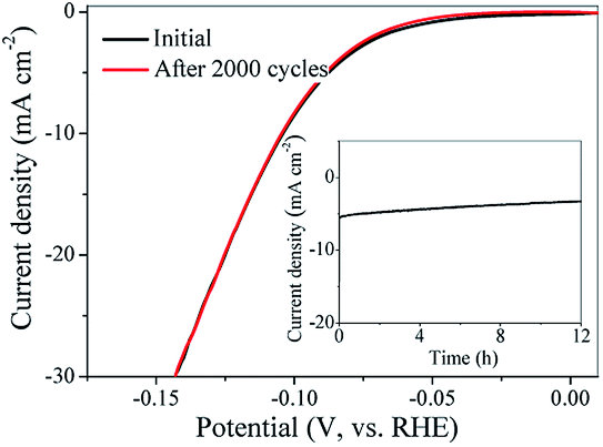 | ||
| Fig. 8 Stability of the Mo2C@NC-160 electrocatalyst with an initial LSV polarization curve and after 2000 cycles. The insert showed the time dependence of catalytic currents for Mo2C@NC-160 at 80 mV overpotential. | ||
Conclusions
In summary, Mo2C@NC was easily synthesized via a one-step strategy by adjusting the mass ratios of urea and ammonium molybdatetetrahydrate. The Mo2C@NC nanomaterials with different N-doped carbon content and crystalline obtained at different ratios all exhibited excellent electrocatalytic HER activity, and Mo2C@NC-160 electrocatalyst showed the best HER activity with a low overpotential of only 90 mV to reach 10 mA cm−2 and a small Tafel slope of 50 mV dec−1. The superior HER activity of Mo2C@NC-160 was associated with highly dispersed ultrasmall Mo2C nanoparticles exhibiting high electrochemically active surface areas, and the synergistic effect of N-doped carbon shell/matrix facilitating the electron transportation.Conflicts of interest
There are no conflicts to declare.Acknowledgements
The work was supported by National Natural Science Foundation of China (Grants 21571140, 21531005, 21371134 and 21703156), 973 Program (2014CB845601), the Program for Innovative Research Team in University of Tianjin (TD13-5074), Tianjin Universities Program for Development of Science and Technology (2017KJ122), and Doctoral Program Foundation of Tianjin Normal University (52XB1508).References
- X. Zou and Y. Zhang, Chem. Soc. Rev., 2015, 44, 5148–5180 RSC.
- A. Eftekhari, Int. J. Hydrogen Energy, 2017, 42, 11053–11077 CrossRef CAS.
- J. Wang, F. Xu, H. Jin, Y. Chen and Y. Wang, Adv. Mater., 2017, 29, 1605838–1605872 CrossRef PubMed.
- L. Song, X. Wang, F. Wen, L. Niu, X. Shi and J. Yan, Int. J. Hydrogen Energy, 2016, 41, 18942–18952 CrossRef CAS.
- M. I. Jamesh, J. Power Sources, 2016, 333, 213–236 CrossRef CAS.
- D. H. Youn, S. Han, J. Y. Kim, J. Y. Kim, H. Park, S. H. Choi and J. S. Lee, ACS Nano, 2014, 8, 5164–5173 CrossRef CAS PubMed.
- B. Cao, G. M. Veith, J. C. Neuefeind, R. R. Adzic and P. G. Khalifah, J. Am. Chem. Soc., 2013, 135, 19186–19192 CrossRef CAS PubMed.
- P. Xiao, M. A. Sk, L. Thia, X. Ge, R. J. Lim, J.-Y. Wang, K. H. Lim and X. Wang, Energy Environ. Sci., 2014, 7, 2624–2629 CAS.
- C. Tsai, H. Li, S. Park, J. Park, H. S. Han, J. K. Norskov, X. Zheng and F. Abild-Pedersen, Nat. Commun., 2017, 8, 15113 CrossRef PubMed.
- S. Meyer, A. V. Nikiforov, I. M. Petrushina, K. Koehler, E. Christensen, J. O. Jensen and N. J. Bjerrum, Int. J. Hydrogen Energy, 2015, 40, 2905–2911 CrossRef CAS.
- C. Lu, D. C. Tranca, J. Zhang, F. Rodriguez-Hernandez, Y. Su, X. Zhuang, F. Zhang, G. Seifert and X. Feng, ACS Nano, 2017, 4, 3933–3942 CrossRef PubMed.
- Z. Shi, K. Nie, Z.-J. Shao, B. Gao, H. Lin, H. Zhang, B. Liu, Y. Wang, Y. Zhang, X. Sun, X.-M. Cao, P. Hu, Q. Gao and Y. Tang, Energy Environ. Sci., 2017, 10, 1262–1271 CAS.
- Z. Shi, Y. Wang, H. Lin, H. Zhang, M. Shen, S. Xie, Y. Zhang, Q. Gao and Y. Tang, J. Mater. Chem. A, 2016, 4, 6006–6013 CAS.
- Z. Shi, B. Gao, Q. Mo, Z. J. Shao, K. Nie, B. Liu, H. Zhang, Y. Wang, Y. Zhang, Q. Gao, X. Sun, X. M. Cao, P. Hu and Y. Tang, ChemNanoMat, 2018, 4, 194–202 CrossRef CAS.
- Y. Wang, Z. Shi, Q. Mo, B. Gao, B. Liu, L. Wang, Y. Zhang, Q. Gao and Y. Tang, ChemElectroChem, 2017, 4, 2169–2177 CrossRef CAS.
- L. Liao, S. Wang, J. Xiao, X. Bian, Y. Zhang, M. D. Scanlon, X. Hu, Y. Tang, B. Liu and H. H. Girault, Energy Environ. Sci., 2014, 7, 387–392 CAS.
- Y. Pan, Y. Liu, J. Zhao, K. Yang, J. Liang, D. Liu, W. Hu, D. Liu, Y. Liu and C. Liu, J. Mater. Chem. A, 2015, 3, 1656–1665 CAS.
- F.-X. Ma, H. B. Wu, B. Y. Xia, C.-Y. Xu and X. W. Lou, Angew. Chem., Int. Ed., 2015, 54, 15395–15399 CrossRef CAS PubMed.
- C. Giordano, C. Erpen, W. Yao and M. Antoniett, Nano Lett., 2008, 8, 4659–4663 CrossRef CAS PubMed.
- C. A. Wolden, A. Pickerell, T. Gawai, S. Parks, J. Hensley and J. D. Way, ACS Appl. Mater. Interfaces, 2011, 3, 517–521 CAS.
- R. Ma, Y. Zhou, Y. Chen, P. Li, Q. Liu and J. Wang, Angew. Chem., Int. Ed., 2015, 54, 14723–14727 CrossRef CAS PubMed.
- C. Tang, A. Sun, Y. Xu, Z. Wu and D. Wang, J. Power Sources, 2015, 296, 18–22 CrossRef CAS.
- J. Song, C. Zhu, B. Z. Xu, S. Fu, M. H. Engelhard, R. Ye, D. Du, S. P. Beckman and Y. Lin, Adv. Energy Mater., 2017, 7, 1601555–1601563 CrossRef.
- Q.-C. Zhu, S.-M. Xu, M. M. Harris, C. Ma, Y.-S. Liu, X. Wei, H.-S. Xu, Y.-X. Zhou, Y.-C. Cao, K.-X. Wang and J.-S. Chen, Adv. Funct. Mater., 2016, 26, 8514–8520 CrossRef CAS.
- J. Mu, J. Li, X. Zhao, E.-C. Yang and X.-J. Zhao, RSC Adv., 2016, 6, 35568–35576 RSC.
- Y. Zhang, J. Liu, G. Wu and W. Chen, Nanoscale, 2012, 4, 5300–5303 RSC.
- K. Ojha, S. Saha, H. Kolev, B. Kumar and A. K. Ganguli, Electrochim. Acta, 2016, 193, 268–274 CrossRef CAS.
- H. Vrubel and X. Hu, Angew. Chem., Int. Ed., 2012, 51, 12703–12706 CrossRef CAS PubMed.
- Y. Zhang, Y. Wang, S. Jia, H. Xu, J. Zang, J. Lu and X. Xu, Electrochim. Acta, 2016, 222, 747–754 CrossRef CAS.
- S. Wang, J. Wang, M. Zhu, X. Bao, B. Xiao, D. Su, H. Li and Y. Wang, J. Am. Chem. Soc., 2015, 137, 15753–15759 CrossRef CAS PubMed.
- Y.-Y. Chen, Y. Zhang, W.-J. Jiang, X. Zhang, Z. Dai, L.-J. Wan and J.-S. Hu, ACS Nano, 2016, 10, 8851–8860 CrossRef CAS PubMed.
- C. Lu, D. Tranca, J. Zhang, F. R. Hernandez, Y. Su, X. Zhuang, F. Zhang, G. Seifert and X. Feng, ACS Nano, 2017, 11, 3933–3942 CrossRef CAS PubMed.
- W. Zhou, J. Zhou, Y. Zhou, J. Lu, K. Zhou, L. Yang, Z. Tang, L. Li and S. Chen, Chem. Mater., 2015, 27, 2026–2032 CrossRef CAS.
- S. Bukola, B. Merzougui, S. E. Creager, M. Qamar, L. R. Pederson and M. N. Noui-Mehidi, Int. J. Hydrogen Energy, 2016, 41, 22899–22912 CrossRef CAS.
- X. Fan, Y. Liu, Z. Peng, Z. Zhang, H. Zhou, X. Zhang, B. I. Yakobson, W. A. Goddard III, X. Guo, R. H. Hauge and J. M. Tour, ACS Nano, 2017, 11, 384–394 CrossRef CAS PubMed.
- L. Huo, B. Liu, G. Zhang and J. Zhang, ACS Appl. Mater. Interfaces, 2016, 8, 18107–18118 CAS.
- Y. Huang, Q. Gong, X. Song, K. Feng, K. Nie, F. Zhao, Y. Wang, M. Zeng, J. Zhong and Y. Li, ACS Nano, 2016, 10, 11337–11343 CrossRef CAS PubMed.
- H. L. Lin, Z. P. Shi, S. N. He, X. Yu, S. N. Wang, Q. S. Gao and Y. Tang, Chem. Sci., 2016, 7, 3399–3405 RSC.
- H. B. Wu, B. Y. Xia, L. Yu, X.-Y. Yu and X. W. Lou, Nat. Commun., 2015, 6, 6512–6519 CrossRef CAS PubMed.
- Y. Liu, G. Yu, G.-D. Li, Y. Sun, T. Asefa, W. Chen and X. Zou, Angew. Chem., Int. Ed., 2015, 54, 10752–10757 CrossRef CAS PubMed.
Footnote |
| † Electronic supplementary information (ESI) available. See DOI: 10.1039/c8ra02020e |
| This journal is © The Royal Society of Chemistry 2018 |