 Open Access Article
Creative Commons Attribution 3.0 Unported Licence
One-time sintering process to synthesize ZrO2-coated LiMn2O4 materials for lithium-ion batteries†
Gang Lia,
Xu Chen a,
Yafei Liub,
Yanbin Chenb and
Wensheng Yang
 *a
*a
aState Key Laboratory of Chemical Resource Engineering, Beijing University of Chemical Technology, Beijing 100029, P. R. China. E-mail: yangws@mail.buct.edu.cn
bBeijing Easpring Material Technology Co., Ltd., Beijing 100160, P. R. China
First published on 8th May 2018
Abstract
Herein, different amounts of ZrO2-coated LiMn2O4 materials are successfully prepared by one-time sintering ZrO2-coated Mn3O4 and Li2CO3. Scanning and transmission electron microscopy results confirm that the ZrO2 coating layer on the surface of Mn3O4 can still be maintained on the surface of the final LiMn2O4 particles even after long-term high-temperature heat-treatment. Three key factors to realize ZrO2-coated LiMn2O4 materials via the one-time sintering process are as follows: (i) the Mn3O4 precursor is coated by ZrO2 in advance; (ii) the ionic radius of Zr4+ is much larger than those of Mn3+ and Mn4+; (iii) the pre-calcination temperature is set in the reaction temperature range between Li2CO3 and Mn3O4 and lower than that between Li2CO3 and ZrO2. The 3 wt% ZrO2-coated LiMn2O4 material exhibits excellent electrochemical properties with an initial specific discharge capacity of 118.8 mA h g−1 and the capacity retention of 90.1% after 400 cycles at 25 °C and 88.9% after 150 cycles at 55 °C. Compared with the conventional coating method, the one-time sintering process to synthesize ZrO2-coated LiMn2O4 materials is very simple, low-cost, environmentally friendly, and easy to scale up for large-scale industrial production, which also provides a valuable reference for preparing other coating-type cathode materials for lithium-ion batteries.
Introduction
Rechargeable lithium-ion batteries (LIBs) have achieved great success as the power sources for portable electronic devices due to their high energy density and long cycle life. Recently, the demand for LIBs has been increasingly shifting from small portable power systems to electric vehicles (EVs) and large-scale energy storage systems (ESSs).1,2 The safety and cost issues are mostly concerned for EVs and ESSs.3,4 LiMn2O4 is one of the most suitable cathode materials owing to its high abundance, low material cost, and high safety.5 However, the practical application of LiMn2O4 is greatly limited due to their poor cycling performance, especially at elevated temperatures (≥55 °C).6 The reasons can be summarized as follows: (1) the dissolution of Mn2+ from cathode to electrolyte via a disproportionation reaction (2Mn3+solid → Mn4+solid + Mn2+electrolyte);7–9 (2) structural transformation from cubic to tetragonal phase, induced by the Jahn–Teller distortion of Mn3+;10,11 (3) the electrolyte decomposition on the electrode surface at high voltage.12To solve the above problems, two strategies, namely the doping and coating techniques, are usually employed to improve the room-temperature (RT) and high-temperature (HT) cycling performance of LiMn2O4 materials. Partial substitution of Mn3+ with other metal ions, such as Li+, Al3+, Co3+, and Cr3+, can stabilize the structure of LiMn2O4 materials, which is attributed to the strong metal–oxygen bonds formed by the doping metals.5,13–15 With regard to the synthetic operations, the doping elements can be easily added in the precursor-synthesizing or the raw-material-mixing processes.16–20 Therefore, no extra processes are needed and the production cost would not be greatly increased.
The coating technology is another effective strategy to improve the cycling performance of LiMn2O4 materials. The coating layer can protect the inner active materials from attack by the acidic species such as HF and oxidation of carbonate solvents at high voltages.21 Many electrochemical inert materials12,22–24 such as ZrO2, Al2O3, TiO2, AlPO4, AlF3 and many coating methods6,25–29 such as sol–gel, wet-coating, spray drying, atomic layer deposition (ALD) have been widely studied. Until now, the coating-type LiMn2O4 materials are usually synthesized by sintering two times: the pristine LiMn2O4 is firstly prepared by calcination at ∼800 °C, and then the LiMn2O4 is coated with some inert materials and followed by re-calcination between 400 °C and 600 °C. Although the coating techniques can effectively improve the cycling performance, they still have some drawbacks. For example, the production cost of ALD is very high, the sol–gel and spray drying methods are of high-energy consumption, and wet-coating method would generate a large amount of wastewater. Therefore, the industrial applications of the current coating techniques are greatly hindered by the complicated or high-cost coating processes.30,31 Consequently, a simple, low-cost, environmental friendly, and easily scaled-up coating technique is urgent to be developed to solve the above problems.
In this work, a one-time sintering process was employed to synthesize ZrO2-coated LiMn2O4 materials. Scanning and high resolution transmission electron microscope (SEM and HRTEM) results clearly demonstrate that the LiMn2O4 particles can be successfully coated by ZrO2 via the one-time sintering process. The electrochemical measurements demonstrate that the RT and HT cycling performances of ZrO2-coated LiMn2O4 materials are greatly enhanced. This one-time sintering process to synthesize ZrO2-coated LiMn2O4 materials is very simple, low-cost, and environmental friendly, which can promote its practical application. Besides, we systematically investigated the key influence factors in the synthesis of ZrO2-coated LiMn2O4 materials via the one-time sintering process, which can provide a valuable reference for synthesizing other coating-type cathode materials for LIBs.
Experimental
Material preparation
The pristine and different amounts of ZrO2-coated LiMn2O4 materials were synthesized by a high-temperature solid-state reaction. The shape and particle size distribution of the raw materials of Mn3O4 (Nanjing Tianyuan Magnetic Material Co., Ltd.) and ZrO2 (Xuan Cheng Jing Rui New Material Co., Ltd.) can be seen in Fig. S1 and S2 in ESI.† The amount of ZrO2 was calculated based on the weight of the final LiMn2O4 material. Therefore, in order to synthesize 1, 3, and 5 wt% ZrO2-coated LiMn2O4, the adding amount of ZrO2 was 1.19, 3.56, and 5.93 wt% of the weight of Mn3O4, respectively.The one-time sintering process to synthesize 3 wt% ZrO2-coated LiMn2O4 is as follows as an example: industrial grade Mn3O4 (100 g) and nano-sized ZrO2 (3.56 g) were firstly weighed and ball-milled for 1 h, and then battery-grade Li2CO3 (25.43 g, Shandong RuiFu Lithium Co., Ltd.) with the molar ratio of Li![[thin space (1/6-em)]](https://www.rsc.org/images/entities/char_2009.gif) :
:![[thin space (1/6-em)]](https://www.rsc.org/images/entities/char_2009.gif) Mn = 1.05
Mn = 1.05![[thin space (1/6-em)]](https://www.rsc.org/images/entities/char_2009.gif) :
:![[thin space (1/6-em)]](https://www.rsc.org/images/entities/char_2009.gif) 2 was added to the above mixed materials and further ball-milled for 3 h. Note that the mass ratio of the agate balls to the raw materials is 1
2 was added to the above mixed materials and further ball-milled for 3 h. Note that the mass ratio of the agate balls to the raw materials is 1![[thin space (1/6-em)]](https://www.rsc.org/images/entities/char_2009.gif) :
:![[thin space (1/6-em)]](https://www.rsc.org/images/entities/char_2009.gif) 1, and the rotational speed of the planetary ball mill is 400 rpm. The obtained mixtures of different amounts of ZrO2-coated Mn3O4 & Li2CO3 was added into alumina crucible, then pre-heated at 550 °C for 5 h and calcined at 800 °C for 20 h in O2 atmosphere. Both of the heating and cooling rates are 3 °C min−1. The calcined samples were crushed down and sifted through a sieve of 325 meshes, thus the final products were obtained. The step for preparing ZrO2-coated Mn3O4 can be ignored in the synthesis of the pristine LiMn2O4.
1, and the rotational speed of the planetary ball mill is 400 rpm. The obtained mixtures of different amounts of ZrO2-coated Mn3O4 & Li2CO3 was added into alumina crucible, then pre-heated at 550 °C for 5 h and calcined at 800 °C for 20 h in O2 atmosphere. Both of the heating and cooling rates are 3 °C min−1. The calcined samples were crushed down and sifted through a sieve of 325 meshes, thus the final products were obtained. The step for preparing ZrO2-coated Mn3O4 can be ignored in the synthesis of the pristine LiMn2O4.
In order to investigate the influence of the blending manners of raw materials on the uniformity of the coating layer on particle surface of the final materials, stoichiometric amount of Mn3O4, Li2CO3, and ZrO2 (Li![[thin space (1/6-em)]](https://www.rsc.org/images/entities/char_2009.gif) :
:![[thin space (1/6-em)]](https://www.rsc.org/images/entities/char_2009.gif) Mn = 1.05
Mn = 1.05![[thin space (1/6-em)]](https://www.rsc.org/images/entities/char_2009.gif) :
:![[thin space (1/6-em)]](https://www.rsc.org/images/entities/char_2009.gif) 2, molar ratio) are added and ball-milled at the same time. The detailed synthetic process can be seen in the ESI.† The obtained sample is denoted as LMO@ZrO2. Additionally, 3 wt% ZrO2-coated LiMn2O4 material was also synthesized by the conventional dry coating method to compare the coating effect of two coating methods.
2, molar ratio) are added and ball-milled at the same time. The detailed synthetic process can be seen in the ESI.† The obtained sample is denoted as LMO@ZrO2. Additionally, 3 wt% ZrO2-coated LiMn2O4 material was also synthesized by the conventional dry coating method to compare the coating effect of two coating methods.
Besides, SiO2 and TiO2 were also used as the coating materials to synthesize different amounts of SiO2- and TiO2-coated LiMn2O4 materials, respectively. The detailed synthetic process can be seen in the ESI.†
Material characterization
The morphologies of the synthesized materials were observed using SEM (Supra 55, Zeiss, Germany) with an energy dispersive X-ray spectroscope (EDX, EDAX, Genesis 60, Germany). The thickness of ZrO2 coating layer was measured using Auger electron spectroscopy (AES, ULVAC-PHI, AES-PHI 700, Japan). Lattice structure and surface feature of samples were investigated using HRTEM (H-800, Hitachi, Japan). Powder X-ray diffraction measurements (XRD, D/MAX 2500, Rigaku, Japan) using Cu Kα radiation (λ = 0.154 nm) were employed to identify the crystalline phase of the synthesized materials. XRD data were obtained in the 2θ range of 10–80°, with a step size of 0.02°, and a count time of 4 s. From the XRD data, the lattice parameters were calculated by the least-squares method. The thermal and weight changes in the synthetic process were investigated with thermogravimetric and differential thermal analysis (TG-DTA, HCT-1, China). TG-DTA measurements of the mixed materials were performed between 25 °C and 850 °C at a heating rate of 3 °C min−1.Electrochemical measurement
The prepared powders were mixed with carbon black and polyvinylidene fluoride (PVDF) with a weight ratio of 80![[thin space (1/6-em)]](https://www.rsc.org/images/entities/char_2009.gif) :
:![[thin space (1/6-em)]](https://www.rsc.org/images/entities/char_2009.gif) 10
10![[thin space (1/6-em)]](https://www.rsc.org/images/entities/char_2009.gif) :
:![[thin space (1/6-em)]](https://www.rsc.org/images/entities/char_2009.gif) 10 in N-methyl-2-pyrrolidinone (NMP) to fabricate the positive electrodes. The obtained slurry was coated onto Al foil, followed by drying at 105 °C for 30 min, and roll-pressed in air. The electrodes were dried overnight at 100 °C in a vacuum oven prior to use. The areal mass loading of the active materials was ∼10 mg cm−2. The CR2032 coin cells were assembled in an argon-filled glove box with an electrolyte of 1 mol L−1 LiPF6 in EC-DMC-DEC (1
10 in N-methyl-2-pyrrolidinone (NMP) to fabricate the positive electrodes. The obtained slurry was coated onto Al foil, followed by drying at 105 °C for 30 min, and roll-pressed in air. The electrodes were dried overnight at 100 °C in a vacuum oven prior to use. The areal mass loading of the active materials was ∼10 mg cm−2. The CR2032 coin cells were assembled in an argon-filled glove box with an electrolyte of 1 mol L−1 LiPF6 in EC-DMC-DEC (1![[thin space (1/6-em)]](https://www.rsc.org/images/entities/char_2009.gif) :
:![[thin space (1/6-em)]](https://www.rsc.org/images/entities/char_2009.gif) 1
1![[thin space (1/6-em)]](https://www.rsc.org/images/entities/char_2009.gif) :
:![[thin space (1/6-em)]](https://www.rsc.org/images/entities/char_2009.gif) 1 weight ratio) solution and a separator of Celgard 2400. The cells were aged for 6 h before the charge/discharge test performed on a LAND CT2001A test system (Wuhan LAND electronics Co. Ltd., China) in the voltage range of 3.0–4.3 V (vs. Li+/Li) at 25 °C and 55 °C. The first 4 cycles were performed at 0.2C (24 mA g−1), and then the following cycles were tested at 1C (120 mA g−1).
1 weight ratio) solution and a separator of Celgard 2400. The cells were aged for 6 h before the charge/discharge test performed on a LAND CT2001A test system (Wuhan LAND electronics Co. Ltd., China) in the voltage range of 3.0–4.3 V (vs. Li+/Li) at 25 °C and 55 °C. The first 4 cycles were performed at 0.2C (24 mA g−1), and then the following cycles were tested at 1C (120 mA g−1).
Results and discussion
As illustrated in Fig. 1, the one-time sintering process to synthesize ZrO2-coated LiMn2O4 materials includes two main procedures: the mixing and sintering processes. In the mixing process, Mn3O4 and nano-sized ZrO2 are firstly ball-milled for 1 h to prepare ZrO2-coated Mn3O4 materials, and then the stoichiometric amount of Li2CO3 is added to the above mixture and further ball-milled for 3 h. The purpose of the above process is to guarantee that most of ZrO2 particles are coated onto the surface of Mn3O4 and would not be coated onto the surface of Li2CO3 particles. | ||
| Fig. 1 Schematic illustration for the one-time sintering process to synthesize ZrO2-coated LiMn2O4 materials. | ||
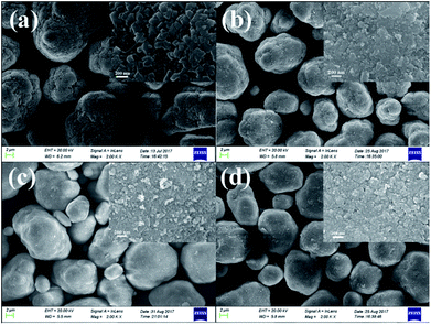
Fig. 2 shows the SEM images of the pristine Mn3O4 and different amounts of ZrO2-coated Mn3O4 materials without any heat-treatment. As shown in Fig. 2a, the pristine Mn3O4 particles have spherical morphology and are composed of the octahedral primary particles with the particle size ranging from 100 to 200 nm. Additionally, we also notice that the Mn3O4 particles have a rough surface and there are many particle boundaries among the primary particles. Fig. 2b–d show the SEM images of different amounts of ZrO2-coated Mn3O4 materials. As illustrated from the low-magnification images in Fig. 2b–d, after ZrO2 coating, the particle boundary on the surface of Mn3O4 particles is gradually blurred with ZrO2 coating amount increasing. In addition, there are no nano-sized ZrO2 particles existing alone even when the coating amount is up to 5.93 wt%. The inset high-magnification SEM images shown in Fig. 2b–d clearly demonstrate that the surface of Mn3O4 is uniformly coated by many ZrO2 particles with the particle size of about 30 nm. The above results indicate that nano-sized ZrO2 can be easily coated on the surface of Mn3O4 particles through the simple dry coating method without adding any dispersant such as alcohol or water.
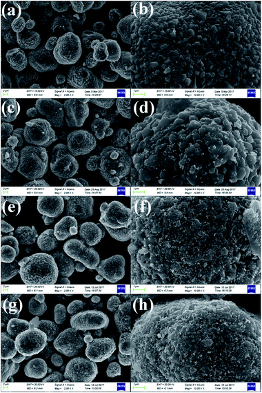
As shown in Fig. 3a, c, e and g, low-magnification SEM images of the pristine and different amounts of ZrO2-coated LiMn2O4 materials heat-treated at 800 °C for 20 h (the coating material is ZrO2, which can be proven in the latter XRD data) illustrate that the spherical morphology is still maintained after long-term high-temperature heat-treatment. The average particle diameter is about 10 μm. Fig. 3b shows that the surface morphology of the pristine LiMn2O4 is smooth and clean. In contrast, the surfaces of the coated LiMn2O4 become rough and are covered with small particles, as shown in Fig. 3d, f and h. The coating layer becomes more and more obviously with the ZrO2 coating amount increasing from 1 to 5 wt%, which demonstrates that the coating layer is still maintained even after having been heat-treated at 800 °C for 20 h.
Lattice structure of the coating layer on LiMn2O4 particles was investigated by HRTEM. As illustrated in Fig. 4a, HRTEM images show that there is a film-like layer as we speculate in SEM images. Fig. 4b and d show that the measured interplanar distances of the coating layer of 3 wt% ZrO2-coated LiMn2O4 and nano-sized ZrO2 heat-treated at 800 °C for 20 h are around 0.218 nm, respectively, which matches well to the (![[1 with combining macron]](https://www.rsc.org/images/entities/char_0031_0304.gif) 21) plane of ZrO2 with monoclinic crystal system. Therefore, we can draw a conclusion that the coating layer on the surface of LiMn2O4 particles is ZrO2.
21) plane of ZrO2 with monoclinic crystal system. Therefore, we can draw a conclusion that the coating layer on the surface of LiMn2O4 particles is ZrO2.
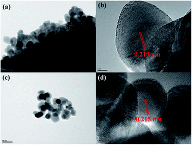 | ||
| Fig. 4 HRTEM images of (a and b) 3 wt% ZrO2-coated LiMn2O4 and (c and d) nano-sized ZrO2 heat-treated at 800 °C for 20 h. | ||
Fig. 5b–d shows elemental mapping studies on 3 wt% ZrO2-coated LiMn2O4 particles. It is clear that the presence of Mn, Zr, and O are homogenous within LiMn2O4 particles, and the ZrO2 coating layer is uniformly distributed on the surface of LiMn2O4 particles.
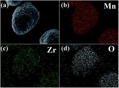 | ||
| Fig. 5 (a) SEM image of 3 wt% ZrO2-coated LiMn2O4 and the corresponding elemental mapping of (b) Mn, (c) Zr, and (d) O. | ||
In order to confirm the extent of inter-diffusion between Zr and Mn ions in the process of high-temperature heat-treatment, EDX was used to measure the Zr/Mn atomic ratio in the particles before and after high-temperature calcination. As illustrated in Fig. 6b, the atomic ratio of Zr/Mn in 3.56 wt% ZrO2-coated Mn3O4 particle is 0.079/99.921. As to the final product of 3.0 wt% ZrO2-coated LiMn2O4 (Fig. 6d), the atomic ratio of Zr/Mn is 0.071/99.929, which is slightly lower than that of 3.56 wt% ZrO2-coated Mn3O4 particle. If all of Zr ions are diffused into the bulk LiMn2O4 particles, the atomic ratio of Zr/Mn would be 0.022/99.978. Therefore, we can draw a definite conclusion that the inter-diffusion between Zr and Mn ions is very little.
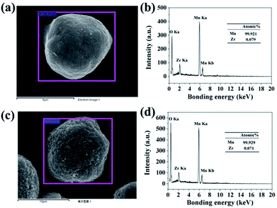 | ||
| Fig. 6 (a) SEM image of 3.56 wt% ZrO2-coated Mn3O4 and (b) its corresponding EDX spectroscopy. (c) SEM image of 3.0 wt% ZrO2-coated LiMn2O4 and (d) its corresponding EDX spectroscopy. | ||
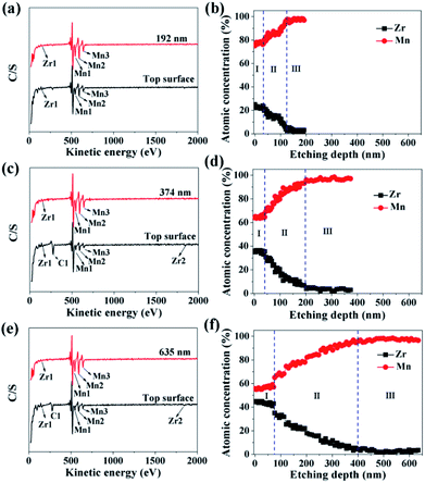
In order to investigate the ZrO2 coating thickness, the theoretical value was firstly calculated. The calculation method can be seen in Fig. S3 in ESI.† The theoretical coating thickness of 1, 3, and 5 wt% ZrO2-coated LiMn2O4 materials is 12.2, 36.6, and 61.0 nm, respectively. AES was also employed to measure the actual coating thickness of different amounts of ZrO2-coated LiMn2O4 materials. From Fig. 7a, c and e, the peaks indexed to Zr1 can be easily observed on the top surface of 1, 3, and 5 wt% ZrO2-coated LiMn2O4 materials. As the Ar+ etching depth increases, the peak intensity of Zr1 decreases, while that of Mn1, Mn2, and Mn3 increases. When the etching depth reaches 192, 374, and 635 nm for 1, 3, and 5 wt% ZrO2-coated LiMn2O4 samples, though the Zr1 peak intensities are weak, they can still be observed, indicating that some Zr ions have diffused into the crystal lattice of LiMn2O4.
As illustrated in Fig. 7b, d and f, the changing trend of the atomic concentration of Zr and Mn can be divided into three stages: in the first stage (stage-I), the atomic concentration of Zr and Mn changes little, so the etching depth in stage-I can represent the thickness of ZrO2 coating layer. Therefore, it can be estimated from Fig. 7b, d and f that the coating thickness of 1, 3, and 5 wt% ZrO2-coated LiMn2O4 samples are 32, 42, and 75 nm, respectively. The measured thickness of the coating layer is slightly bigger than the theoretical value; the main reason is that the actual density of ZrO2 is reduced due to the nano-crystallization of particles. Since ZrO2 is a granular material, not a film material, so the surface coverage will be incomplete if the coating amount is small. As ZrO2 coating amount increases, the surface coverage becomes completely, and then the coating thickness will increase proportionally with the increase of ZrO2 coating amount. Considering that the coating thickness of 3 wt% ZrO2-coated LiMn2O4 sample is only 10 nm bigger than that of 1 wt% ZrO2-coated sample, and the ratio of the coating thickness between 5 wt% and 3 wt% coating amount is 1.786, which is very close to 5![[thin space (1/6-em)]](https://www.rsc.org/images/entities/char_2009.gif) :
:![[thin space (1/6-em)]](https://www.rsc.org/images/entities/char_2009.gif) 3. So, it is speculated that the surface coverage for 1 wt% ZrO2 coating amount is not complete. As the ZrO2 coating amount is ≥3 wt%, the surface coverage becomes completely, which means that the “breakthrough” loading to have a complete coverage should be 3 wt%. In the second stage (stage-II), the atomic concentration of Zr drastically decreases and that of Mn rapidly increases, indicating that Zr ions have diffused into the crystal lattice in the surficial layer of LiMn2O4 particles to form a LiMn2−xZrxO4 phase. According to Fig. 7b, d and f, the thickness of LiMn2−xZrxO4 layer for 1, 3, and 5 wt% ZrO2-coated LiMn2O4 samples are estimated to be 92, 158, and 325 nm, respectively, indicating that more ZrO2 content makes more Zr ions diffuse into LiMn2O4 particles. In the third stage (stage-III), the atomic concentration of Zr is very low and changes very little with the etching depth increasing, indicating that it is very difficult for all of Zr ions to completely diffuse into the crystal lattice of LiMn2O4 particles. From the atomic concentration of Zr in the inner part of LiMn2O4 particles, we can obtain that some Zr ions have been doped to form a LiMn2−xZrxO4 phase (0.01 ≤ x ≤ 0.02).
3. So, it is speculated that the surface coverage for 1 wt% ZrO2 coating amount is not complete. As the ZrO2 coating amount is ≥3 wt%, the surface coverage becomes completely, which means that the “breakthrough” loading to have a complete coverage should be 3 wt%. In the second stage (stage-II), the atomic concentration of Zr drastically decreases and that of Mn rapidly increases, indicating that Zr ions have diffused into the crystal lattice in the surficial layer of LiMn2O4 particles to form a LiMn2−xZrxO4 phase. According to Fig. 7b, d and f, the thickness of LiMn2−xZrxO4 layer for 1, 3, and 5 wt% ZrO2-coated LiMn2O4 samples are estimated to be 92, 158, and 325 nm, respectively, indicating that more ZrO2 content makes more Zr ions diffuse into LiMn2O4 particles. In the third stage (stage-III), the atomic concentration of Zr is very low and changes very little with the etching depth increasing, indicating that it is very difficult for all of Zr ions to completely diffuse into the crystal lattice of LiMn2O4 particles. From the atomic concentration of Zr in the inner part of LiMn2O4 particles, we can obtain that some Zr ions have been doped to form a LiMn2−xZrxO4 phase (0.01 ≤ x ≤ 0.02).
The SEM, HRTEM, EDX, and AES results show that the LiMn2O4 particles can be successfully coated by ZrO2 via the one-time sintering process. This coating method is very easy to be scaled up and can be used to prepare other coating-type cathode materials. However, the successful synthesis of ZrO2-coated LiMn2O4 via the one-time sintering process is just a specific example. In order to make this method more universal, we systematically studied what factors are essential to guarantee its success.
First of all, the blending manner of raw materials may be one of the key factors. In the preceding experiments, the Mn3O4 precursor was coated with nano-sized ZrO2 in advance, and then Li2CO3 was added and further ball-milled for 3 h. Herein, we made an adjustment to the blending manner as below. Three raw materials of Mn3O4, Li2CO3, and ZrO2 (the amount of ZrO2 is 3.56 wt% of the weight of Mn3O4) were ball-milled simultaneously, and then the mixture was preheated at 550 °C for 5 h and then calcined at 800 °C for 20 h. The as-prepared material is denoted as LMO@ZrO2 and deemed as a control sample. SEM images of LMO@ZrO2 are illustrated in Fig. S4(a and b).† It can be seen that there is very small amount of ZrO2 observed on the surface of the LiMn2O4 particles. However, as illustrated in Fig. S4(c and d),† a large number of ZrO2 particles can be successfully coated onto the LiMn2O4 particles through calcining the mixture of Li2CO3 and ZrO2-coated Mn3O4. According to the above comparison results, a definite conclusion can be drawn: only the precursor is coated with the coating material beforehand, can the coating material be uniformly coated onto the surface of the final particles via the one-time sintering process. Besides, it can also be seen from Fig. S4(e and f)† that the coating uniformity of the one-time sintering process is similar to that of the conventional coating method.
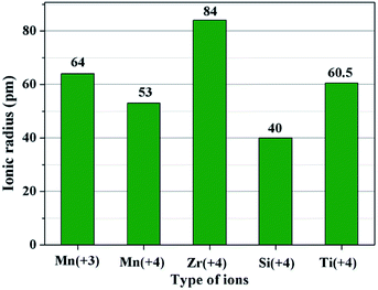
The second key factor may be choosing a suitable coating material. According to the diffusion theory, among the various physicochemical properties of the coating materials, the ionic radius may play an important role.32 In order to prove the above assumption, two other metal ions of Ti4+ and Si4+ are chosen to synthesize different amounts of SiO2- and TiO2-coated LiMn2O4 materials via the one-time sintering process. Unexpectedly, the result obtained from Fig. S6–S9† demonstrates that SiO2- and TiO2-coated LiMn2O4 materials cannot be successfully synthesized by the one-time sintering process, which indicates that it is easy for Si4+ and Ti4+ to diffuse into the bulk LiMn2O4 crystals at 800 °C. In order to compare the ionic radius difference among Mn3+, Mn4+, Zr4+, Si4+, and Ti4+, their ionic radii are shown in Fig. 8. It is seen that Zr4+ has a much larger ionic radius than Mn3+ and Mn4+. While, the ionic radius of Si4+ is much smaller than those of Mn3+ and Mn4+, and the ionic radius of Ti4+ is between those of Mn3+ and Mn4+. From the comparable results of ZrO2, SiO2, and TiO2 coating layers after heat-treatment at 800 °C, we can conclude that the successful synthesis of ZrO2-coated LiMn2O4 via the one-time sintering process is probably due to the much larger ionic radius of Zr4+ than those of Mn3+ and Mn4+. Therefore, the ionic radius is also a crucial factor to realize the coating-type materials via the one-time sintering process.
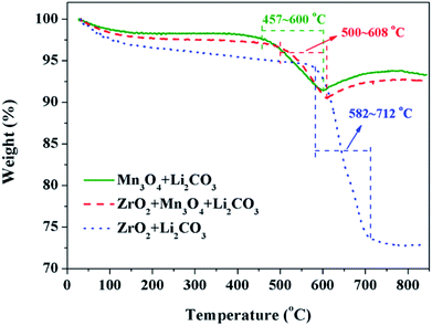
The third key factor should be the choice of the pre-calcination temperature. If the reaction between Li2CO3 and ZrO2 is ahead of that Li2CO3 and Mn3O4, the coating material may be Li2ZrO3 and not ZrO2, thus some extra Li2CO3 will be consumed in vain and the loss of the specific discharge capacity of LiMn2O4 will be more seriously. In order to choose a suitable pre-calcination temperature, TG-DTA was performed to reveal the reaction process between Li2CO3 and ZrO2-coated Mn3O4 and the result is shown in Fig. 9. For the mixture of Li2CO3 and Mn3O4, the reaction temperature range is between 457 °C and 600 °C. While for the mixture of Li2CO3 and ZrO2, the reaction temperature range is between 582 °C and 712 °C. Besides, it is also noticed that when the Mn3O4 is coated with ZrO2 beforehand, the starting reaction temperature between Li2CO3 and Mn3O4 is postponed by 43 °C to 500 °C. This is because Li+ must pass through the ZrO2 coating layer and then can react with Mn3O4 to form LiMn2O4. Although there is overlap in the reaction temperature range between the mixtures of Li2CO3 & ZrO2-coated Mn3O4 and Li2CO3 & ZrO2, it is probably that Li2CO3 would react only with Mn3O4 and not with ZrO2 if the pre-calcination temperature is set at 550 °C.
Influence of the sintering temperature and time on the crystal structure and performance of the pristine LiMn2O4 and different amounts of ZrO2-coated LiMn2O4 materials were investigated in detail. As illustrated in Fig. S10 and S11,† the diffraction peaks of ZrO2 can always be observed between 550 °C to 850 °C, which shows that the coating layer is indeed ZrO2 and the coating layers do not disappear even after long-term high-temperature calcination. Fig. S12† shows the influence of sintering temperature on cyclic performance of the pristine LiMn2O4, and the optimal synthesizing temperature is 800 °C. Fig. S13† demonstrates that the discharge capacity slightly increases and the capacity retention slightly decreases with the sintering time increasing. Therefore, the synthesizing condition of the pristine LiMn2O4 and different amounts of ZrO2-coated LiMn2O4 materials is set at 800 °C for 20 h.
The XRD patterns of the pristine and different amounts of ZrO2-coated LiMn2O4 materials calcined at 800 °C for 20 h are shown in Fig. 10a. The major diffraction peaks of the pristine LiMn2O4 are in good agreement with that obtained from JCPDF file no. 35-0782, corresponding to the cubic spinel structure with Fd![[3 with combining macron]](https://www.rsc.org/images/entities/char_0033_0304.gif) m space group. For the 1 wt% ZrO2-coated LiMn2O4 sample, there is no diffraction peaks corresponding to ZrO2 observed in the XRD pattern, this is because the ZrO2 amount is too low to be detected. As expected, the impurity phase of ZrO2 is obviously observed with the coating amount increasing to 3 wt% and 5 wt%, which demonstrates that most of ZrO2 do not react with Li2CO3. A suitable pre-calcination temperature can guarantee that Li2CO3 does not react with ZrO2 to form Li2ZrO3, which leads to two advantages as below: (i) the weight of the coating layer is not further increased, which will not greatly reduce the specific discharge capacity of the final products; (ii) extra Li2CO3 won't be consumed in vain. Therefore, the suitable pre-calcination temperature is the key factor to determine the chemical compositions of the coating materials.
m space group. For the 1 wt% ZrO2-coated LiMn2O4 sample, there is no diffraction peaks corresponding to ZrO2 observed in the XRD pattern, this is because the ZrO2 amount is too low to be detected. As expected, the impurity phase of ZrO2 is obviously observed with the coating amount increasing to 3 wt% and 5 wt%, which demonstrates that most of ZrO2 do not react with Li2CO3. A suitable pre-calcination temperature can guarantee that Li2CO3 does not react with ZrO2 to form Li2ZrO3, which leads to two advantages as below: (i) the weight of the coating layer is not further increased, which will not greatly reduce the specific discharge capacity of the final products; (ii) extra Li2CO3 won't be consumed in vain. Therefore, the suitable pre-calcination temperature is the key factor to determine the chemical compositions of the coating materials.
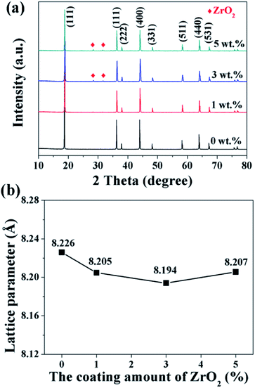 | ||
| Fig. 10 (a) XRD patterns and (b) the lattice parameters of 1, 3, and 5 wt% ZrO2-coated LiMn2O4 materials. | ||
Furthermore, the lattice parameter a (= b = c) is also calculated from the XRD data and the results are shown in Fig. 10b. It is interesting that the lattice parameter of ZrO2-coated LiMn2O4 materials is slightly smaller than that of the pristine LiMn2O4 material. The reason is probably that after heat-treatment at such high temperature of 800 °C for 20 h, a small fraction of Zr4+ diffuses into the spinel lattice of the bulk LiMn2O4 to partial substitute the site of Mn4+. Ionic radius of Zr4+ is much bigger than that of Mn4+, the lattice constant should be bigger if Zr4+ ions substitute the site of Mn4+ in the spinel. But the fact is on the contrary. Actually, the lattice constant of spinel LiMn2O4 crystal is not only related to the ionic radius, but also related to the M–O bond energy.33 The ΔfGΘ(ZrO2) and ΔfGΘ(MnO2) is −1042.8 kJ mol−1 and −465.1 kJ mol−1, respectively. The ΔfGΘ(ZrO2) is much more negative than ΔfGΘ(MnO2), which can deduce that bond energy of Zr–O is much stronger than Mn–O and the crystal volume shrinks. Therefore, the structure with Zr4+ doping is more compact and has smaller lattice constant. Besides, the lattice parameter changes little with ZrO2 content increasing from 1 wt% to 5 wt%, the reason is that the doping content of Zr4+ in the inner part of LiMn2O4 is almost constant, no matter the ZrO2 coating amount is 1 wt%, 3 wt% or 5 wt%. It implies that the upper limit of the actual Zr4+ amounts diffusing into the spinel lattice of LiMn2O4 is very small, primarily because the ionic radius of Zr4+ is much larger than that of Mn4+.
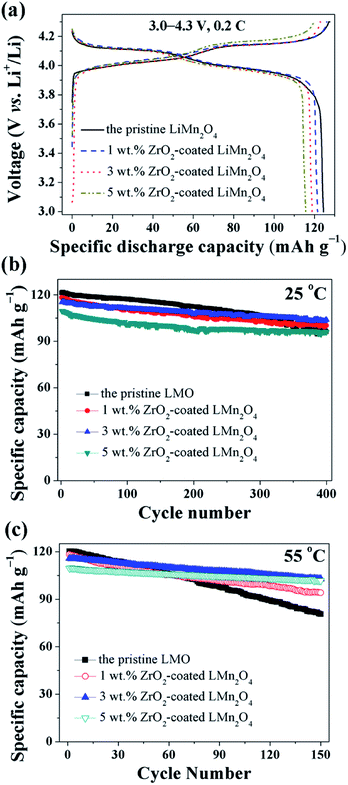
The electrochemical properties of the pristine LiMn2O4 and different amounts of ZrO2-coated LiMn2O4 materials were studied in the voltage range of 3.0–4.3 V at 25 °C and 55 °C. Fig. 11a shows the initial charge–discharge curves of different amounts of ZrO2-coated LiMn2O4 materials at a current rate of 24 mA g−1 corresponding to 0.2C. It can be seen that all discharge curves have two voltage plateaus at approximately 3.95 V and 4.1 V, which is typical for LiMn2O4 and its variants. The two voltage plateaus indicate that the extraction (and subsequent re-insertion) of lithium ions from tetrahedral sites occurs in two stages. The pristine LiMn2O4 material delivers the highest specific discharge capacity of 124.4 mA h g−1 with the initial columbic efficiency of 97.6%. The specific discharge capacities of ZrO2-coated LiMn2O4 materials decrease with the ZrO2 coating amount increasing. The initial discharge capacity of 1, 3, and 5 wt% ZrO2-coated LiMn2O4 is 121.5, 118.8, and 115.6 mA h g−1 with the initial columbic efficiency of 96.4, 96.7, and 96.1%, respectively. The RT and HT cycling performance of the pristine and different amounts of ZrO2-coated LiMn2O4 materials is evaluated with the current density of 120 mA g−1 corresponding to 1C and the results are shown in Fig. 11b and c. At 25 °C, the initial specific discharge capacity of 0, 1, 3, and 5 wt% ZrO2-coated LiMn2O4 materials is 121.3, 118.3, 115.2, and 109.6 mA h g−1 with the 400th capacity retention of 79.2, 84.7, 90.1, and 87.5%, respectively. As the test temperature increases to 55 °C, the pristine LiMn2O4 shows severe capacity loss with the capacity retention of 67.0% after 150 cycles. While the specific discharge capacity of 1, 3, and 5 wt% ZrO2-coated LiMn2O4 after 150 cycles is 94.1, 102.8, and 101.7 mA h g−1 with the capacity retention of 79.5, 88.9, and 92.9%, respectively. Compared with the pristine LiMn2O4, though the specific discharge capacities of ZrO2-coated LiMn2O4 decrease, their cycling performance is greatly improved. By comparison of the comprehensive electrochemical performance, the 3 wt% coating amount is preferred, because it has a relatively high specific discharge capacity and an excellent cycling performance.
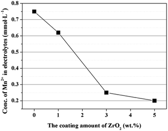
The enhanced cycling performance should be mainly contributed to the ZrO2 coating layer, which can suppress the Mn2+ dissolution from LiMn2O4 cathode into the electrolyte. In order to measure the Mn2+ dissolution, 0.3 g cathode materials were added into 10 mL electrolyte and stored for 7 days at 60 °C, and then the Mn2+ concentration was tested by ICP. As illustrated in Fig. 12, the Mn2+ concentration in electrolyte for the pristine LiMn2O4 is 0.75 mmol L−1. In comparison, the Mn2+ concentrations in electrolyte for 1, 3, and 5 wt% ZrO2-coated LiMn2O4 materials drops quickly to 0.62, 0.25, and 0.2 mmol L−1, which proves that the ZrO2 coating layer can greatly inhibit the Mn2+ dissolution from the active material into the electrolyte.
In order to investigate the stability of the ZrO2 coating layer, SEM and XRD were used to characterize the morphology and crystal structure of 3 wt% ZrO2-coated LiMn2O4 electrode post electrochemical testing, and the results are shown in Fig. S14 and S15.† Based on the analysis of SEM and XRD data, we can conclude that the ZrO2 coating layer on the surface of LiMn2O4 particles is very stable to the volume changes brought by the long-term charge–discharge processes. The reason is probably that the coating layer calcined at 800 °C is very rigid and stable.
Conclusions
In summary, different amounts of ZrO2-coated LiMn2O4 materials are successfully synthesized via a one-time sintering process. Three key factors to realize ZrO2-coated LiMn2O4 materials are as follows: (i) the Mn3O4 precursor is coated by nano-sized ZrO2 in advance; (ii) the ionic radius of Zr4+ is much larger than those of Mn3+ and Mn4+; (iii) the pre-calcination temperature is set in the reaction temperature range between Li2CO3 and Mn3O4 and lower than that between Li2CO3 and ZrO2. The as-prepared 3 wt% ZrO2-coated LiMn2O4 material exhibits an excellent electrochemical performance with the initial specific discharge capacity of 118.8 mA h g−1 at 0.2C and the capacity retention of 90.1% after 400 cycles at 25 °C and 88.9% after 150 cycles at 55 °C at 1C. The enhancement of the cycling performance is mainly contributed to the ZrO2 coating layer which can suppress the side reactions between LiMn2O4 and the electrolyte. Most significantly, the one-time sintering process to synthesize ZrO2-coated LiMn2O4 materials is very simple, low-cost, environmental friendly, and easy for large-scale industrial production, so as to promote its practical application and provide a valuable reference for synthesizing other coating-type cathode materials for LIBs.Conflicts of interest
There are no conflicts to declare.Acknowledgements
This work was financially supported by the National Natural Science Foundation of China (U1407118 and 51272020).Notes and references
- Y. Li, R. Xu, Y. Ren, J. Lu, H. Wu, L. Wang, D. J. Miller, Y. K. Sun, K. Amine and Z. Chen, Nano Energy, 2016, 19, 522–531 CrossRef CAS
.
- S. T. Myung, F. Maglia, K. J. Park, C. S. Yoon, P. Lamp, S. J. Kim and Y. K. Sun, ACS Energy Lett., 2017, 2, 196–223 CrossRef CAS
.
- S. Ahmed, P. A. Nelson, K. G. Gallagher, N. Susarla and D. W. Dees, J. Power Sources, 2017, 342, 733–740 CrossRef CAS
.
- G. Berckmans, M. Messagie, J. Smekens, N. Omar, L. Vanhaverbeke and J. Van Mierlo, Energies, 2017, 10, 1314 CrossRef
.
- W. H. Ryu, J. Y. Eom, R. Z. Yin, D. W. Han, W. K. Kim and H. S. Kwon, J. Mater. Chem., 2011, 21, 15337–15342 RSC
.
- Z. Yang, W. Yang, D. G. Evans, Y. Zhao and X. Wei, J. Power Sources, 2009, 189, 1147–1153 CrossRef CAS
.
- A. Bhandari and J. Bhattacharya, J. Electrochem. Soc., 2017, 164, A106–A127 CrossRef CAS
.
- M. Saulnier, A. Auclair, G. Liang and S. B. Schougaard, Solid State Ionics, 2016, 294, 1–5 CrossRef CAS
.
- J. Lu, C. Zhan, T. Wu, J. Wen, Y. Lei, A. J. Kropf, H. Wu, D. J. Miller, J. W. Elam, Y. K. Sun, X. Qiu and K. Amine, Nat. Commun., 2014, 5, 5693 CrossRef CAS PubMed
.
- Y. Y. Xia, Y. H. Zhou and M. Yoshio, J. Electrochem. Soc., 1997, 144, 2593–2600 CrossRef CAS
.
- K. Ragavendran, H. Xia, P. Mandal and A. K. Arof, Phys. Chem. Chem. Phys., 2017, 19, 2073–2077 RSC
.
- Y. Shang, X. Lin, X. Lu, T. Huang and A. Yu, Electrochim. Acta, 2015, 156, 121–126 CrossRef CAS
.
- F. D. Yu, Z. B. Wang, F. Chen, J. Wu, X. G. Zhang and D. M. Gu, J. Power Sources, 2014, 262, 104–111 CrossRef CAS
.
- K. Suryakala, G. P. Kalaignan and T. Vasudevan, Mater. Chem. Phys., 2007, 104, 479–482 CrossRef CAS
.
- T. Kakuda, K. Uematsu, K. Toda and M. Sato, J. Power Sources, 2007, 167, 499–503 CrossRef CAS
.
- H. Zhao, S. Liu, Y. Cai, Z. Wang, M. Tan and X. Liu, J. Alloys Compd., 2016, 671, 304–311 CrossRef CAS
.
- M. Chen, P. Chen, F. Yang, H. Song and S. Liao, Electrochim. Acta, 2016, 206, 356–365 CrossRef CAS
.
- R. Thirunakaran, A. Sivashanmugam, S. Gopukumar and R. Rajalakshmi, J. Power Sources, 2009, 187, 565–574 CrossRef CAS
.
- Z. Zhang, Z. Chen, G. Wang, H. Ren, M. Pan, L. Xiao, K. Wu, L. Zhao, J. Yang, Q. Wu, J. Shu, D. Wang, H. Zhang, N. Huo and J. Li, Phys. Chem. Chem. Phys., 2016, 18, 6893–6900 RSC
.
- J. Jiang, K. Du, Y. Cao, Z. Peng and G. Hu, J. Nanosci. Nanotechnol., 2015, 15, 421–425 CrossRef CAS PubMed
.
- G. Xu, Z. Liu, C. Zhang, G. Cui and L. Chen, J. Mater. Chem. A, 2015, 3, 4092–4123 CAS
.
- G. H. Waller, P. D. Brooke, B. H. Rainwater, S. Y. Lai, R. Hu, Y. Ding, F. M. Alamgir, K. H. Sandhage and M. L. Liu, J. Power Sources, 2016, 306, 162–170 CrossRef CAS
.
- A. Tron, Y. D. Park and J. Mun, J. Power Sources, 2016, 325, 360–364 CrossRef CAS
.
- J. Y. Shi, C. W. Yi and K. Kim, J. Power Sources, 2010, 195, 6860–6866 CrossRef CAS
.
- J. Zhao and Y. Wang, J. Phys. Chem. C, 2012, 116, 11867–11876 CAS
.
- D. Guan, J. A. Jeevarajan and Y. Wang, Nanoscale, 2011, 3, 1465–1469 RSC
.
- J. Zhao and Y. Wang, Nano Energy, 2013, 2, 882–889 CrossRef CAS
.
- C. G. Han, C. Zhu, G. Saito, N. Sheng, T. Nomura and T. Akiyama, Electrochim. Acta, 2017, 224, 71–79 CrossRef CAS
.
- J. Zeng, M. Li, X. Li, C. Chen, D. Xiong, L. Dong, D. Li, A. Lushington and X. Sun, Appl. Surf. Sci., 2014, 317, 884–891 CrossRef CAS
.
- Y. Cho and J. Cho, J. Electrochem. Soc., 2010, 157, A625–A629 CrossRef CAS
.
- M. G. Kim and J. Cho, Adv. Funct. Mater., 2009, 19, 1497–1514 CrossRef CAS
.
- G. Zhou and L. Duan, The basis of structural chemistry, Peking university press, Beijing, 3rd edn, 2003, p. 312 Search PubMed
.
- C. Q. Xu, Y. W. Tian, Y. C. Zhai and L. Y. Liu, Mater. Chem. Phys., 2006, 98, 532–538 CrossRef CAS
.
Footnote |
| † Electronic supplementary information (ESI) available. See DOI: 10.1039/c8ra01421c |
| This journal is © The Royal Society of Chemistry 2018 |

