DOI:
10.1039/C8RA00983J
(Paper)
RSC Adv., 2018,
8, 15167-15172
Highly efficient degradation of phenol from wastewater via an electro-catalytic oxidation approach with a CeO2–CuO cathode
Received
1st February 2018
, Accepted 10th April 2018
First published on 23rd April 2018
Abstract
The development of highly efficient cathode materials for the electro-catalytic oxidation of phenol from wastewater is of vital importance for environment protection. Herein, we develop an effective CeO2–CuO electrocatalyst for 2-electron oxygen reduction reaction (ORR) to generate H2O2, and then applied it as the cathode for the electro-catalytic oxidation of phenol. Results showed that the CeO2–CuO cathode with different contents of CuO exhibited a higher yield of H2O2 than those of CuO and CeO2, and the highest yield of H2O2 (114 mg L−1) was achieved with a CuO content of 13.4%. The resultant CeO2–CuO-13.4% cathode demonstrated a high degradation rate of 91% after 180 min, which was 1.82-fold and 1.52-fold higher than pure CuO (50%) and CeO2 (60%) electrodes, respectively. Furthermore, the degradation rate of phenol via the electro-catalytic oxidation technology by using a CeO2–CuO cathode significantly outperformed that of the chemical oxidation approach. The outstanding degradation performance of the CeO2–CuO cathode is attributed to the high yield of H2O2 and the strong interaction of CeO2 and CuO.
1 Introduction
The phenolic compound is one kind of hazardous pollutant in wastewater discharged from chemical, petrochemical and pharmaceutical industries,1 which has drawn much public concern due to its highly toxic features. Consequently, a variety of approaches, such as physical adsorption,2 coagulation,3 biological treatment,4 chemical oxidation,5 and electro-catalytic oxidation technology,6 have been adopted to remove phenol from wastewater. Among them, the electro-catalytic oxidation technology is considered to be one of the most effective approaches for the removal of phenol due to its high efficiency, low cost, and environment-friendly features (no serious secondary pollution).7 The electro-catalytic oxidation technology usually involves the electrogeneration of H2O2 in situ via the 2-electron oxygen reduction reaction (ORR) and subsequently generates the hydroxyl radical (˙OH) that can degrade the organic pollutant to form simple organic compounds (e.g., CO2 and/or H2O).8–10 Previously studies indicated that the efficiency of electro-catalytic oxidation technology largely depended on the choice of the cathode materials, in which the carbon materials,9–11 such as graphite, mesh porous carbon, and activated carbon fiber as the electrocatalyst for ORR, have been widely investigated due to their high catalytic activity, low cost, and rich-resources. However, most reported carbon materials still exhibited a low yield of H2O2, causing an insufficient degradation efficiency toward phenol.9,12 Therefore, there is an urgent need but it is still a significant challenge to develop an efficient cathode material with a high yield of H2O2 for the removal of phenol.
Platinum, ruthenium, palladium and other precious metals are the preferred cathode materials13–15 due to their high catalytic activity and good durability. However, their high cost and scarce reserve are hindering the widespread application of precious metals. Hence, considerable attentions have been paid to the development of metal oxides (such as CeO2, CuO, MnO2, and La2O3).16–19 As one of the rare earth oxides, CeO2 has attracted great attention owing to its high oxygen storage capacity and excellent redox property due to the presence of Ce4+/Ce3+.20 Furthermore, CeO2 can promote the generation of H2O2 via catalyzing the 2-electron ORR, and then H2O2 can be decomposed into the oxidative ˙OH,21 which is expected as a promising candidate of cathode materials for the removal of phenol. However, the CeO2 cathode still suffered from a low degradation efficiency probably due to its low catalytic activity of 2-electron ORR with a low yield of H2O2. To further improve the catalytic activity, the CeO2-based metal oxide composites have emerged as effective electrocatalysts due to the strong interaction between CeO2 and other metal oxides.22 It was reported that during the chemical oxidation of phenol, the CeO2–CuO composite cathode exhibited a remarkable catalytic activity for promoting the decomposing of the extra added H2O2, and thus resulting in a high degradation efficiency.23 However, to the best of our knowledge, the CeO2–CuO composite cathode for the degradation of phenol by the electro-catalytic oxidation technology has rarely been reported.
In this work, a highly efficient CeO2–CuO composite cathode for the electro-catalytic oxidation of phenol was synthesized by the sol–gel method. The resultant CeO2–CuO cathode exhibited a high yield of H2O2 as high as 114 mg L−1 after the degradation for 180 min, leading to an excellent degradation performance with the degradation rate of 91%, significantly higher than that of chemical oxidation of phenol (79%). Furthermore, the effect of CuO content on the yield of H2O2 and the degradation performance, and the degradation mechanism of CeO2–CuO were also investigated.
2 Introduction
2.1 Synthesis of the CeO2–CuO electrocatalyst
The CeO2–CuO electrocatalysts with different CuO contents (0, 5.5, 8.5, 13.4, 31.8, and 58 wt%) were prepared by the sol–gel approach, respectively. In the typical synthesis, a certain amount of Ce(NO3)3·6H2O and Cu(NO3)2·3H2O were dissolved into the deionized water and stirred for 0.5 h. Then, 2.1 g of citric acid was added to the above solution with continuously stirring. Afterwards, the mixed solution was heated at 80 °C in a water bath and stewed for 2 h. The resultant product was dried at 100 °C for 12 h and then heat-treated at 700 °C in air atmosphere for 3 h to generate the CeO2–CuO composite.
2.2 Preparation of the CeO2–CuO cathode
The foamed nickel (2 cm × 2 cm) was used as the electrode substrate of cathode. Typically, 0.4 g of graphite and 0.2 g of polytetrafluoroethylene (2% PTFE) were dispersed in ethanol, and then the obtained mixture was homogeneously coated on the foamed nickel. Subsequently, the coated foamed nickel was dried at 100 °C after the pressing treatment to obtain the gas diffusion layer (GDL). Afterwards, a homogeneously dispersed electrocatalyst ink (ultrasonically dispersing 50 mg of electrocatalyst, 0.4 g of Vulcan XC-72 carbon black, and 0.2 g of PTFE in 2.5 mL ethanol and deionized water with a volume ratio of 1) was coated on the GDL, and then the GDL was dried at 100 °C followed by the pressing treatment to obtain the catalyst layer. Finally, the cathode electrode was obtained by the heat-treatment of the catalyst layer at 300 °C for 1 h under the air atmosphere.
2.3 Electro-catalytic degradation of phenol
The electro-catalytic degradation of phenol was conducted in a standard three-electrode system with a graphite sheet (2 cm × 2 cm) as anode and a CeO2–CuO (2 cm × 2 cm) composite as cathode, and a saturated calomel electrode (SCE) as reference electrode. The H2O2 was produced by the reduction of oxygen at cathode in an electrochemical cell with 100 mL of deionized water bubbled with oxygen, and then a certain amount of liquid was extracted in which the concentration of H2O2 was measured at an interval of 20 min. The initial concentration of phenol was 100 mg L−1 and the current density is 40 mA cm−2. The Na2SO4 was used as supporting electrolyte with the concentration of 0.1 mol L−1, and the initial pH of the solution was adjusted to 7.0 by 1 M H2SO4.
2.4 Characterization
The crystal structures of the samples were identified by powder X-ray diffraction (XRD, Rigaku Ultimal II) in the 2θ range of 10–70° at a scanning step of 10° min−1. X-ray photoelectron spectroscopy (XPS) measurements were performed on an ESCALAB 250 electron spectrometer with a monochromatic 150 W Al Kα source with the binding energy calculated referring to C 1s (284.8 eV). The morphology of the as-synthesized samples was examined on scanning electron microscopy (SEM, 23200N, Hitachi) and high resolution transmission microscopy (HR-TEM, Tecnai G220). The inductively coupled plasma (ICP) analysis was conducted with a Shimadzu ICPS-7500 instrument to determine the content of element. Nitrogen sorption measurements were conducted at an AS-AP-2000 instrument to determine the specific surface area (SBET) based on Brunauer–Emmett–Teller (BET) model. The concentration of H2O2 was determined by UV-vis spectrophotometer (mini-1240) at 400 nm with potassium titanyl oxalate (C4K2O9Ti·2H2O) as color indicator. The degradation rate of phenol was measured by a high performance liquid chromatography (HPLC, Agilent 1260).
3 Results and discussion
3.1 Structural characterization
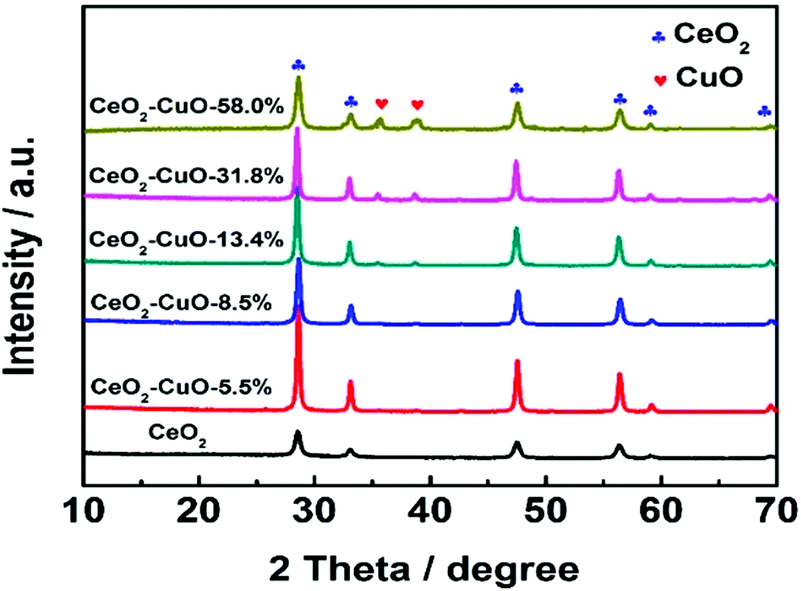
The crystal structures of the CeO2–CuO electrocatalysts with different CuO contents were identified by XRD. As shown in Fig. 1, all the CeO2–CuO electrocatalysts exhibited several strong diffraction peaks at 28.72°, 33.24°, 47.64° and 56.42°, respectively, which are assigned to the (111), (200), (220) and (311) planes of CeO2. Obviously, the intensity of these peaks was significantly higher than that of CeO2, suggesting an improved crystalline of CeO2–CuO composite. However, the typical diffraction peaks of CuO were not detected as the CuO content was lower than 13.4 wt%, probably due to its low content and/or low crystalline. When the CuO content was increased to 13.4 wt%, the typical diffraction peaks of CuO phase appeared. The peaks located at 35.45° and 38.65° are assigned to (![[1 with combining macron]](https://www.rsc.org/images/entities/char_0031_0304.gif) 11) and (111) planes of CuO, respectively, and the intensity of both peaks was found to increase with the increase of CuO content.
11) and (111) planes of CuO, respectively, and the intensity of both peaks was found to increase with the increase of CuO content.
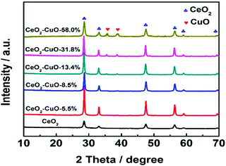 |
| | Fig. 1 XRD patterns of the CeO2–CuO electrocatalysts with different CuO contents. | |
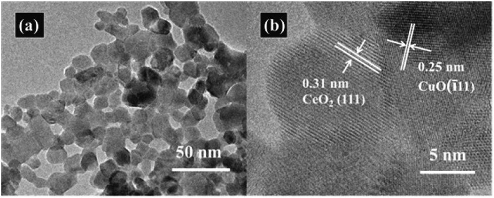
The nitrogen adsorption–desorption measurements were conducted to determine the specific surface area of the CeO2–CuO electrocatalysts. As shown in Table 1, compared with the pure CeO2 (SBET: 43.8 m2 g−1), all the CeO2–CuO electrocatalysts possessed lower specific surface area (SBET: 23.2–40.4 m2 g−1), which might be attributed to the higher crystallinity of CeO2–CuO with large particle size than that CeO2 as indicated by XRD analysis. The TEM images in Fig. 2a displayed that the CeO2–CuO electrocatalyst exhibited a strip-like morphology with the particle size of approximately 20–40 nm. Further HR-TEM observation (Fig. 2b) showed that the lattice fringe spacing of 0.31 nm was corresponded to the (111) plane of CeO2, while the lattice fringe spacing of 0.25 nm was assigned to the (11) plane of CuO. This result further confirmed the formation of CeO2–CuO composite, which was in accordance with the XRD analysis.
Table 1 Specific surface areas of CeO2–CuO with different CuO contents
| Sample |
SBET/m2 g−1 |
| CeO2 |
43.8 |
| CeO2–CuO-5.5% |
40.4 |
| CeO2–CuO-8.5% |
37.1 |
| CeO2–CuO-13.4% |
35.6 |
| CeO2–CuO-31.8% |
30.3 |
| CeO2–CuO-58.0% |
23.2 |
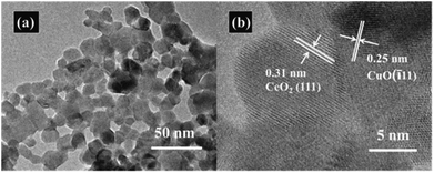 |
| | Fig. 2 Representative TEM image (a) and HR-TEM image (b) of CeO2–CuO-13.4%. | |
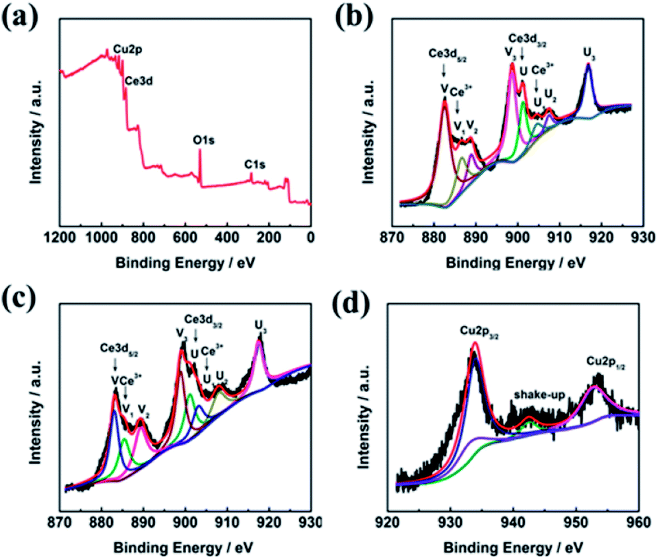
The surface composition and chemical state of the CeO2–CuO electrocatalyst were investigated by XPS measurement. As shown in Fig. 3a, the peaks located at 530 eV, 285 eV, 920–960 eV, and 880–920 eV are ascribed to the O 1s, C 1s, Cu 2p, and Ce 3d, respectively. The C element is likely to due to the indefinite hydrocarbon from the XPS apparatus. The Ce 3d spectra of both CeO2 and CeO2–CuO in Fig. 3b–c can be deconvoluted into eight peaks, in which the peaks labelled as V, V2, V3, U, U2, and U3 are associated with characteristic of Ce4+ state, while the peaks labelled as V1 and U1 are assigned to the Ce3+ state,21 indicating the existence of Ce4+/Ce3+ redox couple in CeO2 and CeO2–CuO. Furthermore, the content of Ce3+ was calculated to be 20.02% for CeO2–CuO, significantly higher than that of CeO2 (14.19%), which probably attributed to the strong interaction between CuO and CeO2. The high content of Ce3+ for CeO2–CuO is believed beneficial for the enhancement concentration of the oxygen vacancy, leading to a superior catalytic activity of 2-electron ORR.21 Furthermore, the binding energies of Ce 3d in CeO2–CuO were all shifted positively in comparison to CeO2, once again confirming a strong interaction between CeO2 and CuO. The XPS spectrum of Cu 2p in Fig. 3d can be deconvoluted into four peaks, in which the peaks located at 933.9 eV, 952.66 eV and the shake-up satellite peak can be assigned to the Cu2+ state,24 while the peak located at 933.06 eV is related to the Cu+ species.25 The presence of Cu+ species is favorable to the generation of ·OH by decomposing H2O2, leading to an enhancement of degradation performance.26
 |
| | Fig. 3 XPS survey spectrum of CeO2–CuO-13.4% (a), and high-resolution Ce 3d spectra of CeO2 (b) and CeO2–CuO-13.4% (c), and high-resolution Cu spectrum of CeO2–CuO-13.4%(d). | |
3.2 Electrogeneration of H2O2 and degradation of phenol
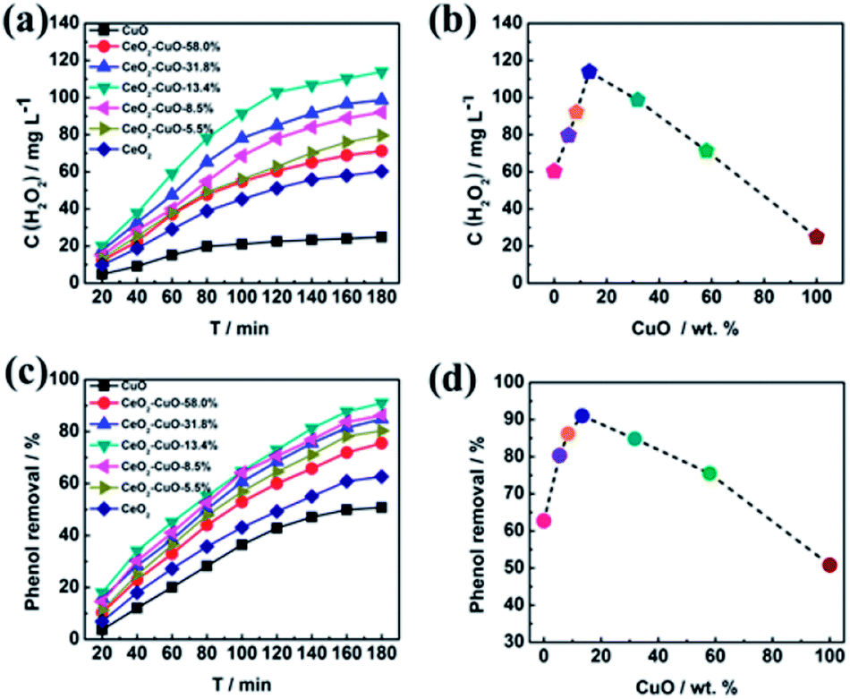
The yield of H2O2 generated via 2-electron ORR (O2 + 2H2O + 4e− → H2O2 + 2OH−) catalyzed by the CeO2–CuO cathode was determined by the UV-vis spectrophotometer (Fig. 4a–b). It was observed that the CuO content had a significant influence on the H2O2 yield, exhibiting a volcano-shaped relation with the highest H2O2 yield at the CuO content of 13.4%. The H2O2 yield for the CeO2–CuO-13.4% cathode was determined as high as 114 mg L−1, significantly outperformed CuO (25 mg L−1) and CeO2 (60 mg L−1), and higher than that of reported CeO2 electrocatalyst in the literature, which is very favorable to promoting the degradation of phenol by the strong oxidizing agents. These results indicated the CeO2–CuO cathode can accelerate the 2-electron ORR pathway to generate a high yield of H2O2.
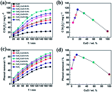 |
| | Fig. 4 Effect of CuO content of CeO2–CuO on the H2O2 yield (a and b) and degradation rate of phenol (c and d). | |
The effect of CuO content on the degradation rate towards phenol was investigated as shown in Fig. 4c–d. For comparison, the degradation rates of phenol by using the pure CeO2 and CuO were also evaluated in the identical condition, respectively. As expected, the CeO2–CuO-13.4% cathode exhibited a highest degradation rate among all the samples, with the degradation rate as high as 91% after the degradation for 180 min, which was significantly higher than those of CuO (50%) and CeO2 (60%). The strong interaction between CeO2 and CuO as indicated by XPS analysis was believed favorable to the generation of high yield of H2O2 and ·OH for the efficient degradation of phenol. These results further confirmed the electro-catalytic oxidation technology by using CeO2–CuO composite cathode was an effective approach for the degradation of phenol.
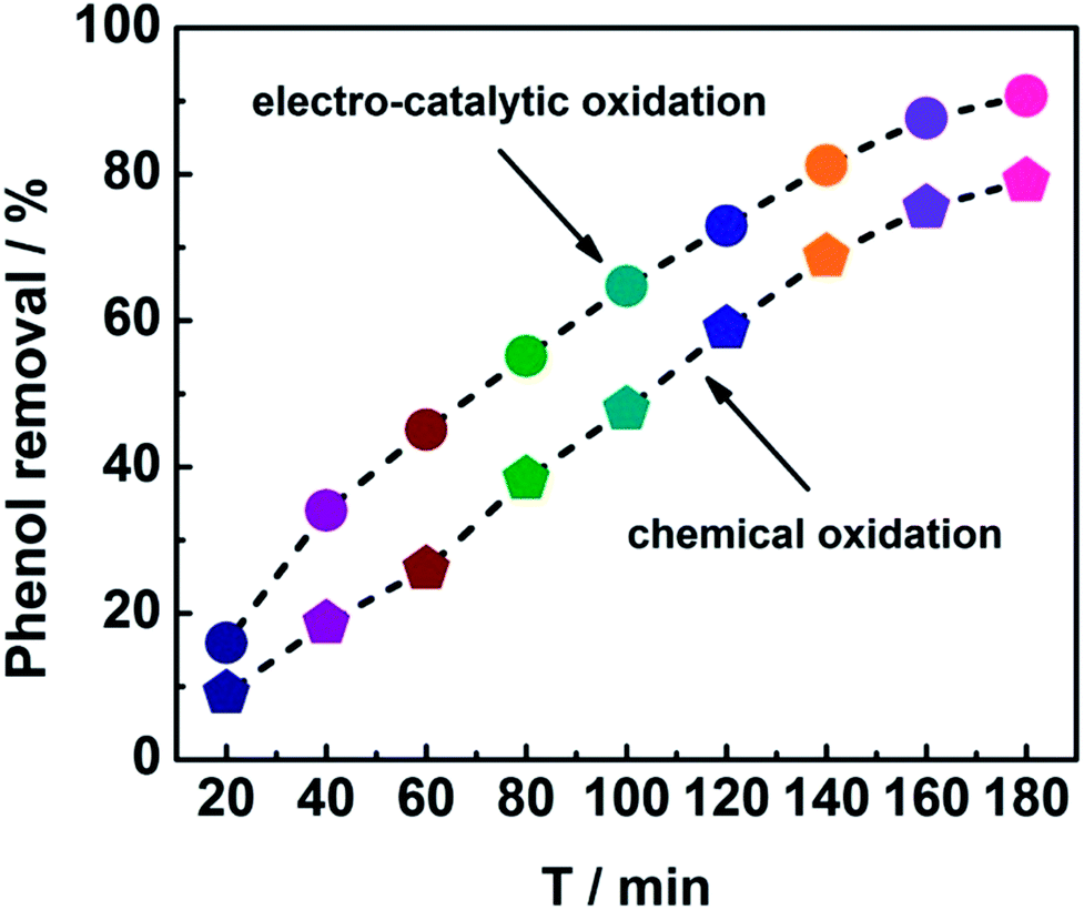
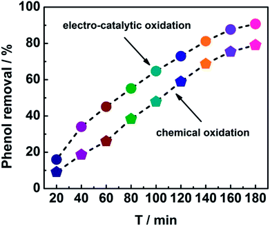
In order to get insight into the merits of the electro-catalytic oxidation technology, the degradation rate of phenol by the chemical oxidation approach using CeO2–CuO cathode was evaluated. As shown in Fig. 5, the degradation rates at different time by the electro-catalytic oxidation technology were all higher than those of the chemical oxidation approach. After the degradation for 180 min, the degradation rate of phenol by the electro-catalytic oxidation (91%) was 1.14-fold of that of the chemical oxidation (80%), indicating that the electro-catalytic oxidation technology is an effective approach for degradation of phenol. Unlike the chemical oxidation approach that required the extra addition of H2O2, the electro-catalytic oxidation technology can produce H2O2 in situ via 2-electron ORR catalyzed by the CeO2–CuO electrocatalyst, promoting the generation of H2O2 and ·OH, and thus leading to a high degradation rate of phenol.
 |
| | Fig. 5 Degradation curves of phenol using CeO2–CuO cathode with the electro-catalytic oxidation and chemical oxidation approaches. | |
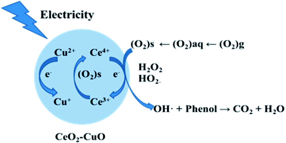
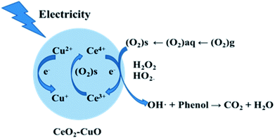
3.3 Degradation mechanism of phenol
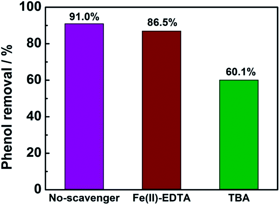
In order to determine the major active species in the electro-catalytic degradation of phenol, Fe(II)–EDTA and tert-butyl alcohol (TBA) were used as the scavengers for H2O2 and ·OH, respectively,21 and the degradation rate of phenol with and without scavengers were evaluated. As shown in Fig. 6, when the scavenger (TBA) of ·OH was added into the solution, the degradation rate of phenol obviously decreased by 31%, while for the addition of H2O2 scavenger (Fe(II)–EDTA), the degradation rate only reduced by 4.5%. This result clearly revealed that ·OH played a more important role for the degradation of phenol than H2O2 in the electro-catalytic oxidation process. In this work, the CeO2–CuO composite was used as the 2-electron ORR electrocatalyst to produce H2O2, and then catalyzed the decomposition of H2O2 to generate HO2− and further turn into ·OH. The generated ·OH can oxidize the phenol to form CO2 and/or H2O (Fig. 7). The reactions are as follows:21| | |
O2 + 2H2O + 2e− → H2O2 + 2OH
| (1) |
| | |
O2 + 2OH− + 2e− → 2HO2−
| (2) |
| | |
H2O2 + HO2− → 2·OH + O2 + H2O
| (3) |
 |
| | Fig. 6 The degradation rate of phenol with or without 10 mL scavengers (1 mol L−1). | |
 |
| | Fig. 7 The degradation mechanism of the electro-catalytic oxidation of phenol with CeO2–CuO cathode. | |
Furthermore, the CeO2–CuO electrocatalyst possessed the redox couples of Ce4+/Ce3+ and Cu2+/Cu+, which can promote the transformation of H2O2 to ·OH. The reactions are as follows:21,26
| | |
Ce3+ + H2O2 → Ce4+ + ·OH
| (6) |
| | |
Cu+ + H2O2 → Cu2+ + ·OH
| (7) |
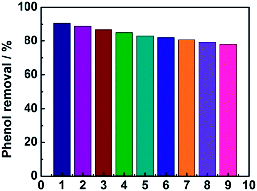
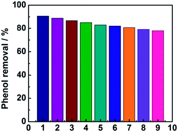
As shown in Fig. 8, the phenol removal rate was only declined from 91% to 80% after nine cycles and no obvious change of the electrode was observed during the experiment, demonstrating that the electrode is stable and favorable for practical application for phenol degradation.
 |
| | Fig. 8 The stability of the electrode investigated by nine successive measurements. | |
4 Conclusions
In summary, an efficient CeO2–CuO electrocatalyst for the 2-electron ORR was synthesized and applied as the cathode for the electro-catalytic oxidation of phenol. Results showed that the CeO2–CuO cathode with different contents of CuO exhibited a higher yield of H2O2 than those of CuO and CeO2, and the highest yield of H2O2 (114 mg L−1) was achieved at CuO content of 13.4%. The resultant CeO2–CuO cathode demonstrated an excellent degradation performance with a removal rate of 91% after the degradation for 180 min, significantly higher than that of CuO (50%) and CeO2 (60%) electrodes, and even higher than that of chemical oxidation approach by using CeO2–CuO cathode (80%). The outstanding degradation performance of CeO2–CuO cathode is attributed to the high yield of H2O2 and strong interaction of CeO2 and CuO. Degradation mechanism analysis indicated that ·OH played a more important role for the degradation of phenol than H2O2 in the electro-catalytic oxidation process.
Conflicts of interest
There are no conflict to declare.
Notes and references
- R. M. Liou and S. H. Chen, J. Hazard. Mater., 2009, 172, 498 CrossRef CAS PubMed.
- B. I. Dvorak and D. A. Boadway, Water Environ. Res., 1993, 65, 827–838 CrossRef CAS.
- X. Hui, R. Jiao, F. Xiao and D. Wang, Colloids Surf., A, 2016, 490, 189–199 CrossRef CAS.
- K. C. Chen, Y. H. Lin, W. H. Chen and Y. C. Liu, Enzyme Microb. Technol., 2002, 31, 490–497 CrossRef CAS.
- M. Pérez, F. Torrades, J. A. García-Hortal, X. Domènech and J. Peral, Appl. Catal., B, 2002, 36, 63–74 CrossRef.
- J. L. Chen, J. Y. Wang, C. C. Wu and K. Y. Chiang, Colloids Surf., A, 2011, 379, 163–168 CrossRef CAS.
- Y. J. Feng and X. Y. Li, Water Res., 2003, 37, 2399–2407 CrossRef CAS PubMed.
- E. Guinea, J. A. Garrido, R. M. Rodríguez, P. L. Cabot, C. Arias, F. Centellas and E. Brillas, Electrochim. Acta, 2010, 55, 2101–2115 CrossRef CAS.
- A. R. Khataee, M. Safarpour, M. Zarei and S. Aber, J. Electroanal. Chem., 2011, 659, 63–68 CrossRef CAS.
- G. Xia, Y. Lu and H. Xu, Electrochim. Acta, 2015, 158, 390–396 CrossRef CAS.
- W. L. Chou, C. T. Wang, C. C. Huang and C. Y. Wang, Fresenius Environ. Bull., 2013, 22, 2234–2241 Search PubMed.
- A. D. Pozzo, L. D. Palma and C. Merli, J. Appl. Electrochem., 2005, 35, 413–419 CrossRef.
- K. J. Kinoshita, J. Electrochem. Soc., 1990, 137, 845–848 CrossRef CAS.
- H. Wang, J. K. Lee, A. Moursi and J. J. Lannutti, Electrochim. Acta, 2008, 53, 6402–6409 CrossRef CAS.
- Y. Zheng, Y. Jiao, Y. Zhu, L. H. Li, Y. Han, Y. Chen, M. Jaroniec and S. Z. Qiao, J. Am. Chem. Soc., 2016, 138, 16174 CrossRef CAS PubMed.
- M. H. M. T. Assumpção, A. Moraes, R. F. B. D. Souza, I. Gaubeur, R. T. S. Oliveira, V. S. Antonin, G. R. P. Malpass, R. S. Rocha, M. L. Calegaro and M. R. V. Lanza, Appl. Catal., A, 2012, 411–412, 1–6 CrossRef.
- D. S. Kim, G. H. Lee, S. Lee, J. C. Kim, H. J. Lee, B. K. Kim and D. W. Kim, J. Alloys Compd., 2016, 275–280 Search PubMed.
- G. Yu, L. Hu, N. Liu, H. Wang, M. Vosgueritchian, Y. Yang, Y. Cui and Z. Bao, Nano Lett., 2011, 11, 4438–4442 CrossRef CAS PubMed.
- N. Wang, J. Liu, W. Gu, Y. Song and F. Wang, RSC Adv., 2016, 6, 77786–77795 RSC.
- L. Jiang, M. Yao, B. Liu, Q. Li, R. Liu, H. Lv, S. Lu, C. Gong, B. Zou and T. Cui, J. Phys. Chem. C, 2012, 116, 11741–11745 CAS.
- L. Yu, X. Yu, T. Sun and N. Wang, J. Nanosci. Nanotechnol., 2015, 15, 4920 CrossRef CAS PubMed.
- W. Yang, D. Li, D. Xu and X. Wang, J. Nat. Gas Chem., 2009, 18, 458–466 CrossRef CAS.
- F. I. P. Massa, P. Haure and R. Fenoglio, J. Hazard. Mater., 2011, 190, 1068–1073 CrossRef PubMed.
- K. N. Rao, P. Venkataswamy and B. M. Reddy, Ind. Eng. Chem. Res., 2011, 50, 11960–11969 CrossRef CAS.
- S. Hočevar, U. O. Krašovec, B. Orel, A. S. Aricó and H. Kim, Appl. Catal., B, 2000, 28, 113–125 CrossRef.
- Y. Cheng, Y. Lin, J. Xu, J. He, T. Wang, G. Yu, D. Shao, W. H. Wang, F. Lu and L. Li, Appl. Surf. Sci., 2016, 366, 120–128 CrossRef CAS.
|
| This journal is © The Royal Society of Chemistry 2018 |
Click here to see how this site uses Cookies. View our privacy policy here. 
 Open Access Article
 This Open Access Article is licensed under a Creative Commons Attribution-Non Commercial 3.0 Unported Licence
 ,
Huan Zhang and
Zenghe Li*
,
Huan Zhang and
Zenghe Li*