 Open Access Article
Design and synthesis of graphene/SnO2/polyacrylamide nanocomposites as anode material for lithium-ion batteries
Yuanxin Wan†
 a,
Tianyi Wang†c,
Hongyan Lu†c,
Xiaoqian Xuc,
Chen Zuoc,
Yong Wang*ab and
Chao Teng*b
aSchool of Advanced Materials, Peking University Shenzhen Graduate School, Shenzhen 518055, China. E-mail: ywang@pkusz.edu.cn
bGuangdong Provincial Key Laboratory of Nano-Micro Material Research Center, School of Chemical Biology & Biotechnology, Peking University Shenzhen Graduate School, Shenzhen 518055, China
cDepartment of Polymer Science and Engineering, School of Chemistry and Chemical Engineering, State Key Laboratory of Coordination Chemistry, Nanjing National Laboratory of Microstructure, Nanjing University, Nanjing, 210093, P. R. China
First published on 27th March 2018
Abstract
Tin dioxide (SnO2) is a promising anode material for lithium-ion batteries owing to its large theoretical capacity (1494 mA h g−1). However, its practical application is hindered by these problems: the low conductivity, which restricts rate performance of the electrode, and the drastic volume change (400%). In this study, we designed a novel polyacrylamide/SnO2 nanocrystals/graphene gel (PAAm@SnO2NC@GG) structure, in which SnO2 nanocrystals anchored in three-dimensional graphene gel network and the polyacrylamide layers could effectively prevent the agglomeration of SnO2 nanocrystals, presenting excellent cyclability and rate performance. A capacity retention of over 90% after 300 cycles of 376 mA h g−1 was achieved at a current density of 5 A g−1. In addition, a stable capacity of about 989 mA h g−1 at lower current density of 0.2 A g−1 was achieved.
1 Introduction
There has been great interest in electric vehicles as a result of shortage of fossil fuels and air pollution. The development of electric vehicles requires higher performance of lithium ion batteries (LIBs).1 Nevertheless, graphite does not satisfy this need owing to its low capacity (372 mA h g−1).2–6 Tin dioxide (SnO2) with an excellent theoretical capacity of 1494 mA h g−1 is a promising material of LIBs anode and has drawn a lot of attention.7–14 However, the application of SnO2 in the industries is restricted by two severe problems. First, the poor conductivity (resistivity 93 Ω m) leads to its low electronic conduction rate and poor multiplier performance. Second, the pulverization problem caused by drastic volume change (∼300%) during lithium insertion and extraction directly leads to severe capacity fading in the cycling.15–26To solve these two problems, much effort has been made, resulting in many significant achievements. Anchoring the SnO2 nanoparticles into carbon-based materials such as graphene or carbon nanotubes (CNTs) is a good way to enhance the conductivity and stability of SnO2-based anode materials.19,24,27–37 In our former study, we successfully anchored SnO2 nanocrystals on 3D graphene to tackle the problems caused by the large volume change of SnO2 during lithiation and delithiation processes.38 Assisted by this structure, high specific capacity and good cycling performance were achieved. However, when the current density is over 5 A g−1 or higher, a significant fall in the capacity occurs during the long cycling test. After careful characterization of the unpacked cell, severe agglomeration of the nanoparticles was found, which directly led to the decay of the capacity at a high current density. Thus, the design of the nanostructure composed of SnO2 and graphene is not strong enough to alleviate the agglomeration of nanoparticles at a high rate.
There were some reports that the composite structure of polymer and graphene would improve the performance of SnO2-based anode.39–41 Moreover, recently, Li et al. reported a cost-effective approach to prepare elastic graphene aerogels with the aid of polyacrylamide (PAAm) during the gelation of a graphene oxide aqueous solution.42 The graphene aerogels modified by PAAm exhibited significantly improved mechanical strength. Inspiringly, we propose an in situ-polymerization method to modify the composite anode with PAAm. In this study, the SnO2 nanoparticles anchored on the surface of graphene were further covered by a layer of polymer to restrict the agglomeration of the SnO2 nanoparticles. Assisted by this polymer layer, the SnO2 nanoparticles were anchored on the surface of graphene, resulting in a considerable increase in the current density. A capacity retention of over 90% after 300 cycles was achieved at a current density of 5 A g−1. Moreover, a stable capacity of about 989 mA h g−1 at lower current density of 0.2 A g−1 was achieved, indicating that the excellent electrochemical performance was still maintained at low current density. This structure directly allayed the agglomeration of SnO2 nanoparticles during cycling, particularly at higher current density.
2 Experimental section
2.1 Synthesis of SnO2 nanoparticles
First, 0.8 g SnCl4·5H2O (Sinopharm Chemical Reagent Co., Ltd.) was dissolved in 40 mL deionized (DI) water and then transferred to a 50 mL poly(tetrafluoroethylene) (Teflon)-lined stainless steel autoclave to be heated at 120 °C for 28 h to obtain a white precipitate, which was further dispersed in 40 mL DI water with a concentration of about 15 mg mL−1.2.2 Synthesis of PAAm@SnO2@GG
GO powder (synthesized by Hummer's method43) was added into SnO2 dispersions and sonicated for several minutes to obtain a concentration of about 5 mg mL−1. Then, 37.5 mg acrylamide (AAm), 1.65 mg methylene-bis-acrylamide (MBAA, the crosslinker), 1.2 mg potassium peroxydisulfate (KPS, the initiator), and 30 mg ascorbic acid (the chemical reducing agent) were added into the SnO2@GG dispersions. The mixed dispersions were placed in an oil bath (90 °C) for 10 min and cooled to 70 °C for 12 h in order to partially reduce GO. Subsequently, the dispersions turned into a weak gel of the reduced GO and polymerized AAm (PAAm). The as-prepared PAAm@SnO2@GG were taken out with a tweezer and blotted with a filter paper to remove surface adsorbed water and subsequently freeze-dried.2.3 Electrode fabrication
The working electrode material consists of 80 wt% polymer@SnO2@GG, 10 wt% super P, and 10 wt% poly(vinylidenefluoride) (PVDF), which was pasted on a rough Cu foil. The loading mass of active material was about 0.9 mg cm−2. The electrolyte used for all the tests was 1 M LiPF6 in ethylene carbonate/diethyl carbonate/dimethyl carbonate (1![[thin space (1/6-em)]](https://www.rsc.org/images/entities/char_2009.gif) :
:![[thin space (1/6-em)]](https://www.rsc.org/images/entities/char_2009.gif) 1
1![[thin space (1/6-em)]](https://www.rsc.org/images/entities/char_2009.gif) :
:![[thin space (1/6-em)]](https://www.rsc.org/images/entities/char_2009.gif) 1 v/v/v, Shenzhen Kejing Star Technology Company). The electrochemical properties were evaluated by galvanostatic cycling of 2032 coin-type half cells with the PAAm@SnO2@GG as the working electrode and lithium foil as the counter/reference electrode. The charge and discharge measurements of the batteries were carried out on a LAND CT2001A system in the fixed voltage window between 0.05 V and 3 V vs. Li+/Li at room temperature. Electrochemical impedance spectral measurements were determined on a PARSTAT 2273 advanced electrochemical system over the frequency range from 100 kHz to 100 mHz. Cyclic voltammetry was also performed on a PARSTAT 2273 advanced electrochemical system at a scan rate of 0.1 mV s−1.
1 v/v/v, Shenzhen Kejing Star Technology Company). The electrochemical properties were evaluated by galvanostatic cycling of 2032 coin-type half cells with the PAAm@SnO2@GG as the working electrode and lithium foil as the counter/reference electrode. The charge and discharge measurements of the batteries were carried out on a LAND CT2001A system in the fixed voltage window between 0.05 V and 3 V vs. Li+/Li at room temperature. Electrochemical impedance spectral measurements were determined on a PARSTAT 2273 advanced electrochemical system over the frequency range from 100 kHz to 100 mHz. Cyclic voltammetry was also performed on a PARSTAT 2273 advanced electrochemical system at a scan rate of 0.1 mV s−1.
3 Results and discussion
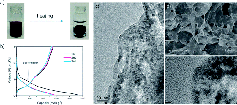
As shown in Fig. 1a, we successfully synthesized PAAm@SnO2NC@GG by thermochemical reduction and in situ polymerization. To further understand the structure of PAAm@SnO2NC@GG, different techniques such as X-ray diffraction (XRD), thermogravimetric analysis (TGA), Fourier transform infrared spectroscopy (IR), scanning electron microscopy (SEM), and transmission electron microscopy (TEM) were performed.Fig. 2a shows the XRD patterns of PAAm@SnO2NC@GG, in which all the peaks are identical. It exhibits prominent peaks at 26°, 33° and 52°, which can be well indexed to the (110), (101) and (211) planes of tetragonal rutile SnO2, respectively (JCPDS #41-1445). In order to quantify the amount of SnO2 in the hybrid, TGA was carried out in the air atmosphere. The samples were heated from 25 °C to 800 °C. Fig. 2b shows the TGA curve for the powders of PAAm@SnO2NC@GG. Clearly, SnO2 remains thermally stable, the content of which in PAAm@SnO2NC@GG composite is about 70%. Fig. 2c shows the FT-IR spectrum of PAAm@SnO2NC@GG, which shows the presence of various groups. In the figure, we can find the peak at 3417 cm−1 attributed to –NH2, the peaks at 2922 cm−1 and 2850 cm−1 assigned to the vibrations of the anti-symmetric and symmetric –CH2– stretching mode, respectively, and the peaks at 1640 cm−1 and 1617 cm−1 attributed to the carbonyl group and the bending vibration of –N–H– on the acylamide, respectively. Furthermore, the remaining bands at 1180 cm−1 and 1114 cm−1 can be assigned to the stretching vibrations of the C–N bond. The IR spectrum indicates the existence of PAAm in the entire structure.
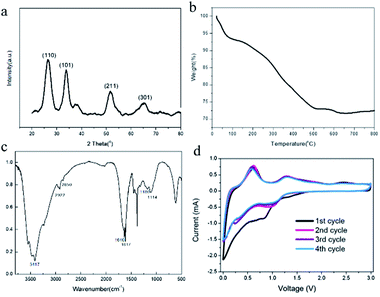 | ||
| Fig. 2 (a) XRD patterns of PAAm@SnO2NC@GG (b) TGA curve of PAAm@SnO2NC@GG (c) IR spectrum of PAAm@SnO2NC@GG (d) CV measurement of PAAm@SnO2NC@GG based cell at a scan rate of 0.1 mV s−1. | ||
Fig. 1d shows the SEM images of PAAm@SnO2NC@GG, which exhibits three-dimensional porous layer structure of densely stacked graphene sheets. Fig. 1c and e show the TEM images of PAAm@SnO2NC@GG. In Fig. 1c, we can find SnO2 nanocrystals well-loaded on the graphene aerogel. Fig. 1e shows that the diameter of SnO2 nanocrystals is around 5 nm. All SEM and TEM images demonstrate that SnO2 nanocrystals are well-dispersed in the 3D graphene gel.
Electrochemical measurements of PAAm@SnO2NC@GG were carried out at room temperature in two-electrode 2031 coin-type half-cells. All the specific capacities and current densities are reported based on the weight of PAAm@SnO2NC@GG hybrid. Cyclic voltammetry (CV) measurements were performed on half cells at a scan rate of 0.1 mV s−1 versus Li/Li+ (Fig. 2d). As shown in Fig. 2d, the cathodic peaks at 0.83 V and close to 0 V in the first cycle could be assigned to the formation of Li2O and LixSn alloy (Sn + xLi+ + xe−1 = LixSn (0 ≤ x ≤ 4.4)), respectively. In addition, the broad peak between 0.5 V and 0.75 V can be ascribed to the decomposition of the electrolyte on the surface of the 3-D graphene in the PAAm@SnO2NC@GG, leading to the formation of solid electrolyte interphase (SEI). During the charging process, the strong peak at 0.63 V and the broad peak at 1.25 V correspond to the phase transition from LixSn alloy and Li2O to SnO2, respectively. The CV curves of the second, third and fourth cycle almost overlap, indicating an excellent cyclability of the PAAm@SnO2NC@GG electrode.
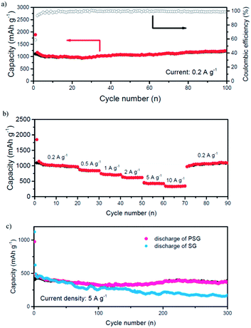
Deep charge/discharge galvanostatic cycling from 3 to 0.05 V was performed to evaluate the electrochemical cycling performance of PAAm@SnO2@GG composite electrodes as shown in Fig. 3a. The results indicated that the PAAm@SnO2@GG composite exhibited excellent cycling stability. Normally, the capacity drop of SnO2-based anode is due to the pulverization of the anode owing to the drastic volume change of SnO2. However, through our composite anode, this problem was resolved due to the three aspects below:
(a) The 3-D graphene framework provides a tight buffer space for the expansion of SnO2, which can avoid the breach by volume change.
(b) The SnO2 nanocrystals are wrapped in the 3-D graphene, so most of the SEI is formed on the surface of graphene sheets and only a small amount of SEI would be unstable due to the huge volume change of SnO2. This can reduce the capacity fade by the reconstruction of SEI.
(c) The 3-D graphene framework provides conductive pathways for the lithium ions and electrons.
Furthermore, the rate performance of PAAm@SnO2NC@GG composite anode is also excellent. As shown in Fig. 3b, while the current densities increase from 0.2 to 0.5, 1, 2, 5 and 10 A g−1, the anode exhibits good capacity retention, varying from around 1000 to 750, 700, 600, 490, and 300 mA h g−1, respectively. When the current density returns to 0.2 A g−1, the charge capacity reverts to around 1000 mA h g−1. The outstanding rate performance should benefit from the conductive 3-D graphene framework and the short diffusion path for the ions and electrons provided by SnO2 nanocrystals constrained in it.
To reveal the influences of PAAm in the composite, we cycled different cells of SnO2NC@GG without polymer and PAAm@SnO2NC@GG at a high current density (5 A g−1) for 300 times. As shown in Fig. 3c, we could easily find that the two electrodes had similar capacity at the beginning of the cycles. However, as the cycling process progressed, capacity fading was found in the SnO2NC@GG electrode. The difference between the results obtained for the two electrodes indicates that the polymer plays an important role in the cycling performance.
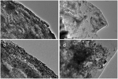
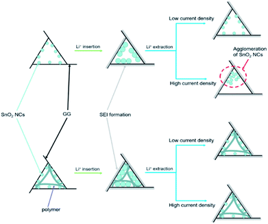
In order to further understand how PAAm influences the cycling process, we removed the two batteries after 300 cycles at a current density of 5 A g−1. The TEM images of the two removed electrodes are shown in Fig. 4. Fig. 4a and b show the TEM images of PAAm@SnO2NC@GG electrode before after cycling, respectively. Fig. 4c and d show TEM images of SnO2NC@GG electrode before and after cycling, respectively. The SnO2 nanocrystals agglomerated in the SnO2NC@GG electrode after 300 cycles (Fig. 4d). In contrast, no agglomeration was found in the PAAm@SnO2NC@GG electrode after 300 cycles (Fig. 4b). Apparently, the capacity loss is because of the agglomeration of SnO2 nanocrystals. To explain the influence of polymer in the composite anode, we put forward a mechanism as shown in Fig. 5. When the SnO2NC@GG electrode was at a low current density, no agglomeration occurs. However, when the current density increases to 5 A g−1, the SnO2 nanocrystals agglomerate severely, resulting in a capacity loss. In the PAAm@SnO2NC@GG electrode, the polymer layer can prevent the nanocrystals from agglomeration. Therefore, excellent stability was obtained at high current density with the help of PAAm. Furthermore, the PAAm will not influence the rate capability.
4 Conclusions
In conclusion, we developed a facile method to synthesize PAAm@SnO2NC@GG composite electrode by thermochemical reduction and in situ polymerization. In this composite structure, the SnO2 nanocrystals were enclosed in the 3D graphene aerogel framework and polymer layers, which provide empty space for accommodation of the drastic volume change of SnO2. Additionally, the PAAm layer improved the performance at a high current density on the basis of excellent performance at lower current density by avoiding the agglomeration. The PAAm@SnO2NC@GG composite electrode delivered an outstanding capacity retention of over 90% after 300 cycles was achieved at a current density of 5 A g−1 and a stable capacity of about 989 mA h g−1 at lower current density of 0.2 A g−1. The novel graphene/SnO2/polyacrylamide ternary nanocomposites provide us a new way to improve high rate capability for lithium-ion batteries.Conflicts of interest
There are no conflicts to declare.Acknowledgements
This study was financially supported by the National Natural Science Foundation of China (No. 21474049, 51673034, 21574063, 21404055, 21272260), the Shenzhen Science and Technology Innovation Committee (JCYJ20160531151102203, JCYJ20160608140827794, JCYJ20160330095448858, GJHZ20170313145533297, JCYJ20170412150857611, JCYJ20160527100441585). We gratefully appreciates the support from the Scientific Research Foundation of Graduate School of Nanjing University.Notes and references
- T. P. Narins, The Extractive Industries and Society, 2017, 4, 321–328 CrossRef.
- Y. Zhuang, Z. Ma, Y. Deng, X. Song, X. Zuo, X. Xiao and J. Nan, Electrochim. Acta, 2017, 245, 440–447 CrossRef.
- J. Xu, F. Xu, M. Qian, F. Xu, Z. Hong and F. Huang, Adv. Mater., 2017, 29, 1617 Search PubMed.
- A. R. Kamali, H.-K. Kim, K.-B. Kim, R. V. Kumar and D. J. Fray, J. Mater. Chem. A, 2017, 5, 19126–19135 CAS.
- Q. Xie, D. Zeng, P. Gong, J. Huang, Y. Ma, L. Wang and D.-L. Peng, Electrochim. Acta, 2017, 232, 465–473 CrossRef CAS.
- M. Huang, K. Mi, J. Zhang, H. Liu, T. Yu, A. Yuan, Q. Kong and S. Xiong, J. Mater. Chem. A, 2017, 5, 266–274 CAS.
- Y. Chen, B. Song, R. M. Chen, L. Lu and J. Xue, J. Mater. Chem. A, 2014, 2, 5688–5695 CAS.
- Z. Chen, M. Zhou, Y. Cao, X. Ai, H. Yang and J. Liu, Adv. Energy Mater., 2012, 2, 95–102 CrossRef CAS.
- H. Z. Li, L. Y. Yang, J. Liu, S. T. Li, L. B. Fang, Y. K. Lu, H. R. Yang, S. L. Liu and M. Lei, J. Power Sources, 2016, 324, 780–787 CrossRef CAS.
- V. M. H. Ng, S. Wu, P. Liu, B. Zhu, L. Yu, C. Wang, H. Huang, Z. J. Xu, Z. Yao, J. Zhou, W. Que and L. B. Kong, Electrochim. Acta, 2017, 248, 440–448 CrossRef CAS.
- H. Xu, J. Chen, D. Wang, Z. Sun, P. Zhang, Y. Zhang and X. Guo, Carbon, 2017, 124, 565–575 CrossRef CAS.
- Z. Ying, Q. Wan, H. Cao, Z. T. Song and S. L. Feng, Appl. Phys. Lett., 2005, 87, 59–64 Search PubMed.
- W. Zhang, M. Li, X. Xiao, X. Huang, Y. Jiang, X. Fan and L. Chen, J. Alloys Compd., 2017, 727, 1–7 CrossRef CAS.
- M. Armand and J.-M. Tarascon, Nature, 2008, 451, 652–657 CrossRef CAS PubMed.
- H. He, M. Xu, J. Yang, B. He and J. Xie, Micro Nano Lett., 2017, 12, 777–780 Search PubMed.
- J.-I. Lee, J. Song, Y. Cha, S. Fu, C. Zhu, X. Li, Y. Lin and M.-K. Song, Nano Res., 2017, 10, 4398–4414 CrossRef CAS.
- H. Xu, J. Chen, D. Wang, Z. Sun, P. Zhang, Y. Zhang and X. Guo, Carbon, 2017, 124, 565–575 CrossRef CAS.
- Y. Wan, X. Xu, J. Liu, Y. Sha, Y. Chen, L. Li, G. Xue, X. Wang and D. Zhou, Adv. Mater. Technol., 2017, 2, 1600156 CrossRef.
- Y. Wan, Y. Sha, W. Deng, Q. Zhu, Z. Chen, X. Wang, W. Chen, G. Xue and D. Zhou, Electrochim. Acta, 2015, 167, 69–74 CrossRef CAS.
- X. Zhou, L. J. Wan and Y. G. Guo, Adv. Mater., 2013, 25, 2152–2157 CrossRef CAS PubMed.
- Y. Li, S. Wang, P.-K. Lee, J. He and D. Y. W. Yu, J. Power Sources, 2017, 366, 226–232 CrossRef CAS.
- X. Tao, Q. Tian, L. Yang and Y. Xiang, Mater. Lett., 2017, 202, 107–110 CrossRef CAS.
- Q. Tian, P. Chen, Z. Zhang and L. Yang, Carbon, 2017, 118, 634–641 CrossRef CAS.
- Y. Wu, Y. Chen, J. Lin, R. Chu, J. Zheng, C. Wu and H. Guo, J. Mater. Sci., 2017, 52, 8097–8106 CrossRef CAS.
- W. Chen, S. Maloney and W. Wang, Nanotechnology, 2016, 27, 382 Search PubMed.
- Y. Wan, S. Ye, W. Deng, Q. Zhu, Z. Chen, X. Wang, W. Chen, G. Xue and D. Zhou, Electrochim. Acta, 2015, 167, 69–74 CrossRef CAS.
- M.-S. Wang, Z.-Q. Wang, Z.-L. Yang, Y. Huang, J. Zheng and X. Li, Electrochim. Acta, 2017, 240, 7–15 CrossRef CAS.
- X. Wang, X. Zhou, K. Yao, J. Zhang and Z. Liu, Carbon, 2011, 49, 133–139 CrossRef CAS.
- C. Zhu, Z. Chen, S. Zhu, Y. Li, H. Pan, X. Meng, M. Imtiaz and D. Zhang, Sci. Rep., 2017, 7, 461 CrossRef PubMed.
- S. Wang, L. Shi, G. Chen, C. Ba, Z. Wang, J. Zhu, Y. Zhao, M. Zhang and S. Yuan, ACS Appl. Mater. Interfaces, 2017, 9, 17164–17172 Search PubMed.
- J. Ye, J. An, B. Liu and C. Xu, Int. J. Hydrogen Energy, 2017, 42, 5199–5206 CrossRef CAS.
- C.-L. Hsieh, D.-S. Tsai, W.-W. Chiang and Y.-H. Liu, Electrochim. Acta, 2016, 209, 332–340 CrossRef CAS.
- X. Du, T. Yang, J. Lin, T. Feng, J. Zhu, L. Lu, Y. Xu and J. Wang, ACS Appl. Mater. Interfaces, 2016, 8, 15598–15606 CAS.
- M. Alaf and H. Akbulut, J. Power Sources, 2014, 247, 692–702 CrossRef CAS.
- X. Meng, Y. Zhong, Y. Sun, M. N. Banis, R. Li and X. Sun, Carbon, 2011, 49, 1133–1144 CrossRef CAS.
- M. Liu, Y. Liu, Y. Zhang, Y. Li, P. Zhang, Y. Yan and T. Liu, Sci. Rep., 2016, 6, 876 Search PubMed.
- J.-Y. Lin, M.-H. Chou and Y.-C. Kuo, J. Alloys Compd., 2014, 589, 472–478 CrossRef CAS.
- Y. Wan, Y. Sha, S. Luo, W. Deng, X. Wang, G. Xue and D. Zhou, J. Power Sources, 2015, 295, 41–46 CrossRef CAS.
- R. Liang, H. Cao, D. Qian, J. Zhang and M. Qu, J. Mater. Chem., 2011, 21, 17654–17657 RSC.
- W. Wang, Q. Hao, W. Lei, X. Xia and X. Wang, RSC Adv., 2012, 2, 10268–10274 RSC.
- Y. Zhao, Y. Huang and Q. Wang, Ceram. Int., 2013, 39, 6861–6866 CrossRef CAS.
- C. Li, L. Qiu, B. Zhang, D. Li and C. Y. Liu, Adv. Mater., 2016, 28, 1510–1516 CrossRef CAS PubMed.
- W. S. Hummers Jr and R. E. Offeman, J. Am. Chem. Soc., 1958, 80, 1339 CrossRef.
Footnote |
| † These authors contributed equally to this work. |
| This journal is © The Royal Society of Chemistry 2018 |

