 Open Access Article
A reactive electrochemical filter system with an excellent penetration flux porous Ti/SnO2–Sb filter for efficient contaminant removal from water†
Kui Yangab,
Hui Lin *b,
Shangtao Liangc,
Ruzhen Xied,
Sihao Lvb,
Junfeng Niub,
Jie Chenb and
Yongyou Hu
 *ae
*ae
aSchool of Environment and Energy, South China University of Technology, Guangzhou 510006, P. R. China. E-mail: 201520132411@mail.scut.edu.cn; ppyyhu@scut.edu.cn; Fax: +86-20-3938-0508; Tel: +86-136-0274-6125
bSchool of Environment and Civil Engineering, Dongguan University of Technology, Dongguan 523808, P. R. China. E-mail: linhui@bnu.edu.cn; 23817001@qq.com; junfengn@bnu.edu.cn; 1875898657@qq.com; Fax: +86-769-3901-8706; Tel: +86-769-3901-8706
cAECOM Inc., Environment, Atlanta, Georgia 30309, USA. E-mail: sliang@uga.edu
dCollege of Architecture and Environment, Sichuan University, Chengdu 610065, P. R. China. E-mail: xieruzhen@scu.edu.cn
eThe Key Lab of Pollution Control and Ecosystem Restoration in Industry Clusters, Ministry of Education, South China University of Technology, Guangzhou Higher Education Mega Centre, Guangzhou, 510006, PR China
First published on 16th April 2018
Abstract
Tubular porous Ti/SnO2–Sb filters with excellent penetration flux (∼61.94 m3 m−2 h−1 bar−1) and electrochemical activity were prepared by a sol–gel method using low-cost porous titanium filters as the substrates. The porous Ti/SnO2–Sb filters were used as anodic reactive electrochemical membranes to develop reactive electrochemical filter systems, by combining membrane filtration technology with the electrooxidation process, for water treatment. A convection-enhanced rate constant of 4.35 × 10⁻⁴ m s−1 was achieved for Fe(CN)64− oxidation, which approached the kinetic limit and is the highest reported in an electrochemical system. The electrooxidative performance of the reactive electrochemical filter system was evaluated with 50 mg L−1 rhodamine B (RhB). The results showed that the reactive electrochemical filter system in flow-through mode resulted in an 8.6-fold enhancement in RhB oxidation as compared to those in flow-by mode under the same experimental conditions. A normalized rate constant of 5.76 × 10⁻⁴ m s−1 for RhB oxidation was observed at an anode potential of 3.04 V vs. SCE, which is much higher than that observed in a reactive electrochemical filter system with carbon nanotubes and/or Ti4O7 (1.7 × 10⁻⁵–1.4 × 10⁻⁴ m s−1). The electrical energy per order degradation (EE/O) for RhB was as low as 0.28 kW h m−3 in flow-through mode, with a relatively short residence time of 9.8 min. The overall mineralization current efficiency (MCE) was calculated to be 83.6% with ∼99% RhB removal and ∼51% TOC removal. These results illustrate that this reactive electrochemical filter system is expected to be a promising method for water treatment.
1. Introduction
The electrooxidation process has emerged as a promising technique for the destruction of various toxic refractory organic pollutants in aqueous solutions due to its mild reaction conditions, strong oxidation ability, easy operation and environmental compatibility.1 Recently, it has been successfully applied in treating industrial wastewater including paper production wastewater,2 textile wastewater,3–5 landfill leachate6,7 and refractory perfluorinated compounds.8,9However, the relatively long retention time and low current efficiency limit its large-scale application. This is because electrooxidation reactions are specific to heterogeneous catalysis, and the mass transfer rate of the traditional electrooxidation process limits the overall efficiency of the reaction system.10 Traditional electrooxidation reactors typically use parallel plate electrodes, in which wastewater is pumped through the narrow flow channel (in the range of mm to cm) between the anode and cathode either in one-pass or recirculation mode. This is defined as flow-by mode. In this fluid dynamic state, a thin stagnant boundary layer is formed near the surface of the electrode. In addition, hydroxyl radicals (˙OH) formed via the oxidation of water on the anode surface can react unselectively with a wide range of organics at an extremely high reaction rate (∼1010 L mol−1 s−1).11,12 Experimental studies and modeling data suggest that the reaction between organics and ˙OH only occurs in a narrow zone, within 1 μm around the anode surface.11,12 However the boundary layer of the electrode surface is thicker than 100 μm in typical flow-by modes,10 which is much thicker than the thickness of the reaction zone between organics and ˙OH. Under this circumstance, the diffusion of organics to the reaction zone is extremely difficult, resulting in a low normalized mass transfer rate constant of 10−6 to 10−5 m s−1.10,13,14 Therefore the reaction rate is limited by the mass transfer rate, which lowers the overall current efficiency.
In order to overcome the mass transfer limitation in the traditional electrooxidation process, researchers have utilized TinO2(n−1) (n = 4 to 6) conductive ultrafiltration ceramic membranes13,15–17 or carbon nanotube (CNT) networks14,18–20 as anodes to build anodic reactive electrochemical filter systems, by combining membrane filtration technology with the electrooxidation process, in flow-through mode for water treatment. The thickness of the boundary layer is a function of the cross-flow velocity and/or the turbulence of the flow. In flow-through mode, water moves adjectively through the pores on the electrode materials. This process minimizes the thickness of the boundary layer, thus greatly improving the mass transfer rate of pollutants moving towards the anode surface zone. However, TinO2(n−1) conductive ceramic ultrafiltration membranes with nanopores may be easily contaminated because industrial effluents tend to be of poor water quality and adding a pre-treatment increases the total cost. CNTs are not active for ˙OH production, and their high cost further limits the large-scale application of CNT networks. Consequently, it’s urgent to seek inexpensive, porous electrode materials with macropores with excellent permeability for water treatment. Recently, Li et al.21 prepared a porous Ti/SnO2–Sb anode in flow-through mode from porous titanium tubes with an average pore size of 2.5 μm to degrade pyridine. Compared to the traditional flow-by mode, the flow-through mode increased the pyridine degradation rate by 43.9%. However, the mass transfer efficiency of this electrochemical system was not mentioned.
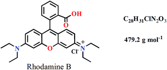
As typical “non-active” electrodes, Sb-doped SnO2 anodes have many advantages such as cost-effectiveness, being easy to prepare, high oxygen evolution potential and good catalytic activity.21–24 Thus, in this study, we focus on understanding the mechanism of electrooxidation by studying the mass transfer rate of a flow-through system using tubular Ti/SnO2–Sb filters, with an average pore size of about 30 μm, as reactive electrochemical membranes. The standard probing molecule Fe(CN)64− was used to assess the mass transfer performance of the reactive electrochemical filter system for direct oxidation (outer-sphere charge transfer). Rhodamine B (RhB, the molecular structure is shown below) was chosen as a model refractory organic pollutant because RhB is a common dye in the triphenylmethane family and has been used extensively in the textile, printing, food and cosmetic industries.25,26 The effects of the operating mode and the applied anode potential on the performance of the reactive electrochemical filter system were investigated. To further verify the feasibility of the reactive electrochemical filter system for water treatment, mineralization current efficiency and energy consumption were also assessed.
2. Experimental
2.1. Materials
Commercially available sintered powder porous tubular titanium filters (Baoji Yinggao Metal Material Co., Ltd. China) with inner and outer diameters of 26 and 30 mm, respectively, and a length of 100 mm were used as substrates. Sodium hydroxide (NaOH), oxalic acid (C2H2O4), anhydrous sodium sulfate (Na2SO4), ethylene glycol (C2H6O2), citric acid (C6H8O7), potassium ferricyanide (K3Fe(CN)6) and potassium ferrocyanide (K4Fe(CN)6) were obtained from Tianjin Damao Chemical Reagent Co., Ltd. Tin chloride pentahydrate (SnCl4·5H2O), antimony trichloride (SbCl3) and rhodamine B (RhB) were obtained from Aladdin Reagent Co., Ltd. All of the chemicals were reagent grade or higher.2.2. Porous Ti/SnO2–Sb filter preparation
The substrate tubular porous titanium filters were firstly immersed in NaOH solution (10%, m/m) at 90 °C for 1 h to remove grease, and then etched in boiling oxalic acid (10%, m/m) for 1 h to form a gray surface with uniform roughness. Tubular porous Ti/SnO2–Sb filters were prepared by the sol–gel method using a dip coater (SYDC-200, Shanghai Sanyan Technology Co., Ltd. China). The preparation process involved the following steps: citric acid and ethylene glycol were mixed and agitated at 60 °C until fully dissolved, and then the solution was heated to 90 °C under continuous stirring. A mixture of SnCl4·5H2O and SbCl3 was added to the solution at the molar ratio of 140![[thin space (1/6-em)]](https://www.rsc.org/images/entities/char_2009.gif) :
:![[thin space (1/6-em)]](https://www.rsc.org/images/entities/char_2009.gif) 30
30![[thin space (1/6-em)]](https://www.rsc.org/images/entities/char_2009.gif) :
:![[thin space (1/6-em)]](https://www.rsc.org/images/entities/char_2009.gif) 9
9![[thin space (1/6-em)]](https://www.rsc.org/images/entities/char_2009.gif) :
:![[thin space (1/6-em)]](https://www.rsc.org/images/entities/char_2009.gif) 1 (ethylene glycol
1 (ethylene glycol![[thin space (1/6-em)]](https://www.rsc.org/images/entities/char_2009.gif) :
:![[thin space (1/6-em)]](https://www.rsc.org/images/entities/char_2009.gif) citric acid
citric acid![[thin space (1/6-em)]](https://www.rsc.org/images/entities/char_2009.gif) :
:![[thin space (1/6-em)]](https://www.rsc.org/images/entities/char_2009.gif) SnCl4·5H2O
SnCl4·5H2O![[thin space (1/6-em)]](https://www.rsc.org/images/entities/char_2009.gif) :
:![[thin space (1/6-em)]](https://www.rsc.org/images/entities/char_2009.gif) SbCl3) at 90 °C and the resulting mixture was maintained at 90 °C for 1 h in order to obtain a sol–gel. Finally, the sol–gel solution was used to coat the porous titanium filters through dipping at a rate of 200 μm s−1. After that, the porous titanium filters were dried at 140 °C for 20 min in an oven and sintered to induce the thermal decomposition of the coating at 550 °C for 20 min in a muffle furnace. The above operation was repeated 12 times and the last baking was annealed for 2 h at 550 °C to obtain the tubular porous Ti/SnO2–Sb filters. More information concerning the Ti/SnO2–Sb electrode preparation has been given elsewhere.27
SbCl3) at 90 °C and the resulting mixture was maintained at 90 °C for 1 h in order to obtain a sol–gel. Finally, the sol–gel solution was used to coat the porous titanium filters through dipping at a rate of 200 μm s−1. After that, the porous titanium filters were dried at 140 °C for 20 min in an oven and sintered to induce the thermal decomposition of the coating at 550 °C for 20 min in a muffle furnace. The above operation was repeated 12 times and the last baking was annealed for 2 h at 550 °C to obtain the tubular porous Ti/SnO2–Sb filters. More information concerning the Ti/SnO2–Sb electrode preparation has been given elsewhere.27
2.3. Experimental setup
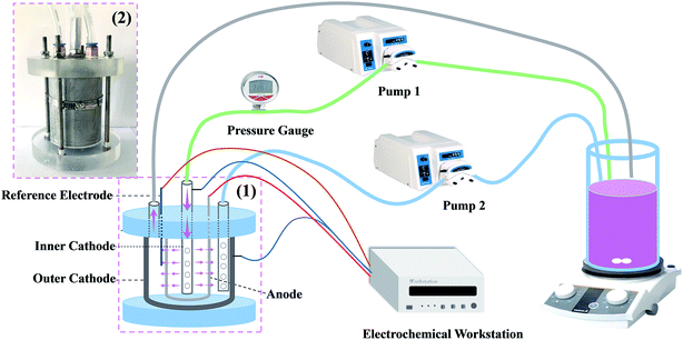
The experimental setup of the reactive electrochemical filter system is shown in Fig. 1. The tubular porous Ti/SnO2–Sb filter was used as the anode and a stainless steel perforated tube with an outside diameter of 6 mm and a length of 150 mm was used as the inner cathode, which was also used as a water distributor. A stainless steel tube mold with an inside diameter of 50 mm and a length of 100 mm was used as the outer cathode. The anode and the cathodes were 10 mm apart. The electrochemical workstation (PARSTAT 2273, USA) provided a stable current for the reaction system. In flow-by mode, pump 2 was turned on and pump 1 was turned off; the solution flowed only by the surface of the electrode and then out of the reactor. In flow-through mode, pump 1 was on and pump 2 was off; the solution flowed from the inside of the electrode to the outside of the reactor after passing through the electrode.2.4. Electrode characterization
The surface morphology of the electrode was characterized by scanning electron microscopy (SEM, Hitachi S-4800, Japan). The crystalline phases of the electrode were measured by X-ray diffraction (XRD, Rigaku D/max-3C, Japan) with Cu Kα radiation at a scanning rate of 2° min−1 in 2θ mode from 20° to 80°. The surface composition of the electrode was characterized by X-ray photoelectron spectroscopy spectra (XPS, ESCALAB 250Xi, USA) with a monochromatic Al Kα source. The pore size distributions and porosity of the electrode were characterized by mercury porosimetry (AutoPore IV 9500, Micromeritics). The pressure–membrane flux relation was calculated according to the different inlet flow and corresponding pressure values in flow-through mode. The linear sweep voltammetry (LSV) scanning and cyclic voltammetry (CV) scanning were carried out on the system in flow-through mode and were driven by an electrochemical workstation (PARSTAT 2273, USA), with a tubular porous Ti/SnO2–Sb filter as the working electrode, two stainless steel tubes as the counter electrode and a saturated calomel electrode (SCE) as the reference electrode.2.5. Electrochemical experiments
The electrochemical experiments were performed using the setup shown in Fig. 1. The normalized mass transfer rate constant (km, m s−1) for the pollutant diffusion to the electrode surface in flow-through mode was characterized using the electrooxidation rate constant of Fe(CN)64−, in which oxidation only occurred on the anode surface through direct electron transfer (for details, see Text S1†). In this experiment, 2 L of 0.1 M KH2PO4 with 5 mM K4Fe(CN)6 and 1 mM K3Fe(CN)6 solution was continuously flowed and recirculated in flow-through mode.The electrochemical degradation of RhB was conducted using a 1 L solution containing 50 mM Na2SO4 and 50 mg L−1 RhB in the reactive electrochemical filter system at an inlet flow rate of 1.8 L min−1. Both the feed and permeate streams were 100% recycled for 10 min to purge the system at zero current, then an input current between 0.25 A and 1.5 A was applied to the reactive electrochemical filter system. Triplicate samples of 5 mL each were taken at different time intervals. During each sampling, the electrolysis was stopped and the solution was kept looping to ensure the solution was homogeneous. All of the electrolysis experiments were triplicated and carried out at room temperature (25 ± 1 °C). The corresponding results were averaged with a standard deviation below 10% of the means.
2.6. Analytical methods
The concentrations of RhB and Fe(CN)63− were determined by UV-vis spectrophotometry (UV-5100B, Shanghai Yuanxi Analysis Instrument Co., Ltd. China) at the wavelengths of 553 and 420 nm, respectively. The total organic carbon (TOC) was measured by a TOC analyzer (TOC-L CPH, Shimadzu Co., Ltd. Japan).The RhB degradation rate (η, %) was calculated according to the following equation:
 | (1) |
 | (2) |
 | (3) |
 | (4) |
![[thin space (1/6-em)]](https://www.rsc.org/images/entities/char_2009.gif) 485C mol−1), V is the treatment solution volume (L), and n = 156 is the electron number required to completely mineralize one molecule of RhB, and n = 28 and n = 12 are the number of carbon atoms contained in each RhB molecule and the atomic mass of carbon, respectively. The electrical energy consumption, EE/O, was calculated to evaluate the energy efficiency of the reactive electrochemical filter system. The EE/O is defined as the energy required to reduce the concentration of the target pollutant by one order of magnitude. The EE/O (kW h m−3) was calculated according to the following equation:29
485C mol−1), V is the treatment solution volume (L), and n = 156 is the electron number required to completely mineralize one molecule of RhB, and n = 28 and n = 12 are the number of carbon atoms contained in each RhB molecule and the atomic mass of carbon, respectively. The electrical energy consumption, EE/O, was calculated to evaluate the energy efficiency of the reactive electrochemical filter system. The EE/O is defined as the energy required to reduce the concentration of the target pollutant by one order of magnitude. The EE/O (kW h m−3) was calculated according to the following equation:29
 | (5) |
3. Results and discussion
3.1. Physical characterization
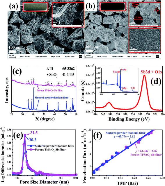
The photos and SEM images of the substrate, sintered powder porous tubular titanium filter, and the fabricated porous Ti/SnO2–Sb filter are shown in Fig. 2. As shown in Fig. 2(a), the surface of the substrate after cleaning and corrosion treatment appears very rough, which contributes to the coating by the sol precursor solution. After the sol–gel preparation process, the Ti/SnO2–Sb filter maintained its highly porous structure, and the size of the aperture did not appear to change significantly (see Fig. 2). From the enlarged view in Fig. 2(b), we can observe that the Sb-doped SnO2 coating on the surface of the porous Ti/SnO2–Sb filter is compacted and crack-free, which helps prolong the service life of the porous Ti/SnO2–Sb filter.28Fig. 2(c) shows the wide-angle XRD analysis of the substrate and the fabricated porous Ti/SnO2–Sb filter. A series of diffraction peaks for the titanium metal and SnO2 structures were recorded using the fabricated porous Ti/SnO2–Sb filter. Diffraction peaks for Sb and its oxide were not observed, however Fig. 2(d) shows the presence of Sb in the porous Ti/SnO2–Sb filter. Therefore, we infer that Sb is well-dispersed in the SnO2 lattice and forms a Sb-doped SnO2 solid solution.30 Compared with the standard card (JCPDS card no: 41-1445), the Sb-doped SnO2 coating film is identified as a rutile-type crystal. Additionally, no crystallized TiO2 diffraction peak was found, which strongly suggested that the titanium support substrate is not oxidized during the Sb-doped SnO2 coating film preparation.
The pore structure and pore size distribution were characterized more thoroughly using Hg intrusion porosimetry as is shown in Fig. 2(e). The intrusion pore volumes of the substrate and the Ti/SnO2–Sb filter were almost unchanged, which was attributed to the macropores of 6–60 μm. The median pore diameters (based on volume) of the substrate and the Ti/SnO2–Sb filter were 31.5 μm and 30.2 μm, respectively. The median pore diameter (based on volume) of the Ti/SnO2–Sb filter was 31.5 μm, slightly larger than that of the substrate (30.2 μm). This is mainly caused by oxalic acid corrosion during the substrate pre-treatment.
Penetration flux is an important indicator for the performance of porous membrane-like materials, and it was used to characterize the permeability of the porous Ti/SnO2–Sb filter. The pressure–membrane flux relationship is shown in Fig. 2(f). Due to the similar pore diameters of the substrate and the porous Ti/SnO2–Sb filter, the pure water membrane flux of the substrate and the porous Ti/SnO2–Sb filter is almost the same (see Fig. 2(e)). The pure water penetration flux of the porous Ti/SnO2–Sb filter is as high as 61.94 m3 m−2 h−1 bar−1, thus both the permeability and water treatment capacity are superior compared with the reactive electrochemical membranes reported in the literature, including TinO2(n−1) conductive ceramic membranes (0.05 m3 m−2 h−1 bar−1 to 3.21 m3 m−2 h−1 bar−1)13,27,31 and CNT-networks (0.017 m3 m−2 h−1 to 0.34 m3 m−2 h−1).14 As a result, the reactive electrochemical filter system in this work can maintain a high water flux under low-pressure conditions, which makes it easy to operate during water treatment.
3.2. Electrochemical characterization
The linear polarization curves of the porous Ti/SnO2–Sb filter are displayed in Fig. 3(a) and the measured oxygen evolution potentials (OEP) are 1.74 V and 1.87 V (vs. SCE) in neutral and acidic conditions, respectively. The high oxygen evolution over-potential indicated a low side reaction of oxygen formation, which would be beneficial for promoting the oxidation efficiency of pollutants during electrocatalytic oxidation processes. Therefore, the electrode has a better electrochemical performance in acidic conditions.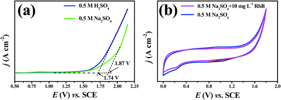 | ||
| Fig. 3 (a) The linear polarization curves and (b) cyclic voltammetry curves of the porous Ti/SnO2–Sb filter at a scan rate of 50 mV s−1. Penetration flux: 12.3 m3 m−2 h−1. | ||
The cyclic voltammetry (CV) curves of the porous Ti/SnO2–Sb filter in 0.5 M Na2SO4 solution and 0.5 M Na2SO4 solution with 10 mg L−1 RhB were generated to investigate the reaction type of RhB degradation in the reactive electrochemical filter system in this study. As shown in Fig. 3(b), no additional peaks were found in Na2SO4 with RhB solution compared to the CV curve recorded in Na2SO4 solution, indicating that the direct electrooxidation of RhB over the porous Ti/SnO2–Sb filter did not occur.21 Obviously, we can conclude that an indirect ˙OH attack plays a key role in the RhB electrooxidation process in flow-through mode.
The electrochemical stability of the tubular porous Ti/SnO2–Sb filter was also evaluated. Fig. S1† shows the results of the accelerated service life test on the porous Ti/SnO2–Sb filter at a current density of 0.5 A cm−2 in 0.5 M H2SO4 solution at 30 °C. It was observed that the accelerated service life time was about 10.23 h when the cell voltage increased from 5 V to 10 V. The actual service life can be calculated by the following equation:
 | (6) |
The electrochemically active surface area is where active sites are accessible to the electrolyte when the electrochemical reaction occurs.33 Voltammetric charge (q*), which is closely related to the real surface area and the number of electro-active sites on an electrode (especially for a porous electrode), is a major factor for determining the electrochemical performance of an electrode.34–36 The CV curves of the tubular porous Ti/SnO2–Sb filter electrode, performed within the potential range of 0.4 V to 1.2 V vs. SCE in 0.5 M Na2SO4 solution in flow-through mode at different sweep rates as shown in Fig. S2(a),† are used to calculate the q* by integrating the CV over the whole potential range to further calculate the electrochemical porosity and roughness factor (Rf) (for details, see Text S2, Fig. S2(b) and S2(c)†).
The values of the charges, electrochemical porosity, and Rf are calculated and listed in Table S2.† As shown in Table S2,† the electrochemical porosity and Rf of the porous Ti/SnO2–Sb filter are 73.3% and 1428.2 ± 37.2, respectively. These values for the electrochemical porosity and roughness factor indicate that the porous Ti/SnO2–Sb filter is three-dimensional in nature, and hence could provide large numbers of active sites for electrocatalytic oxidation.
3.3. The mass transfer performance of the reactive electrochemical filter system
To investigate the mass transfer performance of the reactive electrochemical filter system in flow-through mode, the kinetics of Fe(CN)64− oxidation (kobs) were measured as a function of penetration flux (J, m s−1). It should be noted that the penetration flux of the porous Ti/SnO2–Sb filter is extremely high, i.e. 61.94 m3 m−2 h−1 bar−1. Such a high flux means that the permeability of the porous Ti/SnO2–Sb filter is pretty good and even gravity flow can be achieved. The penetration fluxes tested in this study are also very high (up to 5.17 × 10⁻³ m s−1 or 18.6 m3 m−2 h−1), tens to hundreds of times higher than that reported in the previous literature.13,14,27,30 As shown in Fig. 4, it is very interesting that the kobs values were plateauing at around 4.2 × 10⁻⁴ m s−1 and at a penetration flux greater than 3.01 × 10⁻³ m s−1, the kobs values only increased by 4.5% when the penetration fluxes were enhanced by 1.72 times from 3.01 × 10⁻³ m s−1 to 5.17 × 10⁻³ m s−1 (or 10.8–18.6 m3 m−2 h−1). These results strongly suggest that the Fe(CN)64− oxidation process at very high penetration fluxes is controlled by kinetic limitation rather than mass transfer. To the best of our knowledge, the measured kobs value (4.35 × 10⁻⁴ m s−1) in this study is the highest in an electrochemical flow-through reactor compared with those reported in the literature. The measured kobs values were 3.1-fold and 4.4-fold higher than the highest value reported for Ti4O7-based reactive electrochemical membranes (1.4 × 10⁻⁴ m s−1)13 and CNT network based reactive electrochemical filters (1.0 × 10⁻⁴ m s−1)37. More contrastive details are shown in Table S3.†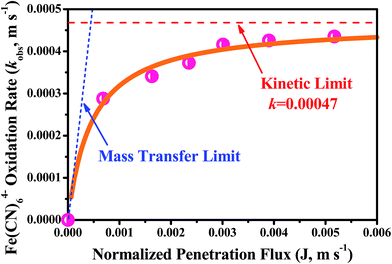 | ||
| Fig. 4 A plot of the normalized observed rate constant (kobs, m s−1) for Fe(CN)64− oxidation in the reactive electrochemical filter system operated in flow-through mode as a function of penetration fluxes (J, m s−1). The solid orange line represents eqn (7), the model fit, the red dashed line is the normalized kinetic rate constant (k, m s−1) estimated by model fit to experimental data, and the blue dotted line is the convective mass transfer limit calculated by kobs = J. Experimental solution: 2 L of 0.1 M KH2PO4 with 5 mM K4Fe(CN)6 and 1 mM K3Fe(CN)6 solution. | ||
Fitting the measured kobs values with eqn (S4)† yielded a value of k = (4.7 ± 0.08) × 10−4 m s−1, which is the assumed kinetic limit. Our k value is 2.8 times higher than the value reported by Chaplin (1.7 × 10⁻⁴ m s−1) who used a Ti4O7-based reactive electrochemical ultrafiltration membrane13. This is mainly attributable to the great roughness factor (Rf = 1428.2 ± 37.2) of the Sb-doped SnO2 coating layer, which was much higher than that of the Ti4O7-based reactive electrochemical ultrafiltration membrane (Rf = 246.3 ± 11.4), which provided much more electrochemical reactive sites. A conservative estimation of the boundary diffusion length (δ) was calculated by δ = D/k, where D = 7.6 × 10⁻¹⁰ m2 s−1 is the water diffusion coefficient for Fe(CN)63−. Based on k = 4.7 ± 0.08 × 10⁻⁴ m s−1 a value of δ = 1.6 μm was estimated, which is much lower than the average pore radius (about 15 μm). These results support the hypothesis that the reactive electrochemical filter system with the porous Ti/SnO2–Sb filter, with excellent water permeability, developed in this study could greatly improve the mass transfer of the electrochemical process by reducing the thickness of the boundary diffusion layer. Additionally, these results also suggest that for further improvement of the intrinsic kinetic reactivity of the reactive electrochemical filter system, it is necessary to design new electrode materials with higher specific electroactive surface area or roughness.
3.4. Electrooxidation performance of the reactive electrochemical filter system
| Operating mode | Input current (A) | Average cell voltage (V) | Anode potential (V vs. SCE) | RhB oxidation at 30 min | Pseudo-first-order rate constants (kRhB, min−1) | R2 | Half-life (t1/2, min) | t90% (min)a | Observed rate constant (kobs, RhB, m s−1)b | Mineralization current efficiency (MCE) at 30 min | Energy consumption (EE/O, kW h m−3) |
|---|---|---|---|---|---|---|---|---|---|---|---|
| a t90% is the time required for 90% RhB degradation (h).b kobs, RhB is calculated by eqn (S3).† | |||||||||||
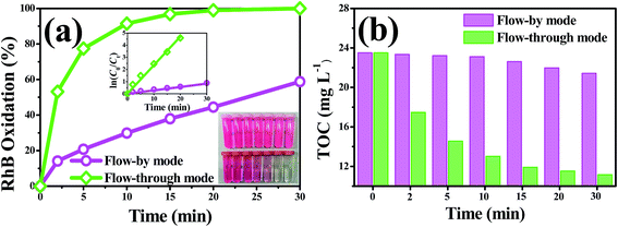
| Flow-by | 0.5 | 3.5 | 2.25 | 58.8% | 0.0274 | 0.992 | 25.3 | 84.0 | 0.53 × 10⁻⁴ | 9.6% | 2.45 |
| Flow-through | 0.25 | 3.0 | 1.94 | 97.6% | 0.135 | 0.994 | 5.1 | 17.1 | 3.01 × 10⁻⁴ | 104.1% | 0.21 |
| Flow-through | 0.5 | 3.4 | 2.18 | >99.9% | 0.235 | 0.994 | 2.9 | 9.8 | 4.65 × 10⁻⁴ | 57.5% | 0.28 |
| Flow-through | 1.5 | 4.2 | 3.04 | >99.9% | 0.304 | 0.975 | 2.3 | 7.6 | 5.76 × 10⁻⁴ | 19.2% | 0.82 |
3.5. The RhB oxidation flux, mineralization current efficiency and mechanism
To better understand the oxidative capacity of the system with the porous Ti/SnO2–Sb filter and to better facilitate the design of reactive electrochemical filter water treatment systems, the RhB oxidation flux (OF, mol h−1 m−2) was calculated using eqn (2), similar to the membrane flux. The RhB oxidation flux was examined as a function of the operating mode and anode potential, as displayed in Fig. 7(a). As expected, it was observed that the RhB oxidation flux in flow-through mode was much higher than that in flow-by mode. For a 99% RhB oxidation, an oxidation flux value of 0.033 mol m−2 h−1 was achieved in flow-through mode at an anode potential of 2.18 V vs. SCE, approximately 8.5 times higher than that in flow-by mode (0.0039 mol m−2 h−1) under the same experimental conditions. This is mainly due to the excellent mass transfer performance in flow-through mode, resulting in the rapid diffusion of RhB molecules towards the anode surface reaction zone. RhB molecules are thus able to react with the ˙OH generated by the porous Ti/SnO2–Sb filter. Additionally, the oxidation flux increased with the increasing anode potential in flow-through mode. At an anode potential of 3.04 V vs. SCE, about 99% of 0.10 mM (50 mg L−1) RhB was oxidized with an oxidation flux of 0.044 mol m−2 h−1, which was about 1.8 times higher than the value for tetracycline (0.2 mM) reported by Liu (0.024 mol h−1 m−2) who used a CNT reactive electrochemical filter in flow-through mode.28 More contrastive information is shown in Table S4.†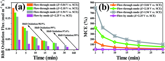 | ||
| Fig. 7 (a) The RhB oxidation flux and (b) the overall mineralization current efficiency (MCE) vary with treatment time. The experimental conditions are the same as in Fig. 5 and 6. | ||
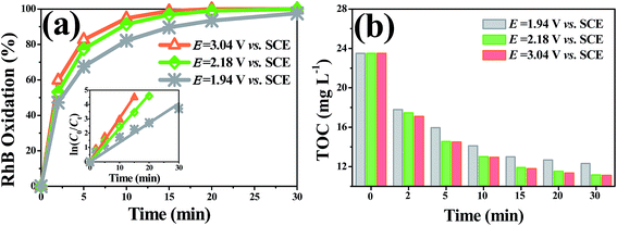
As shown in Fig. 7(b) and Table 1, the overall mineralization current efficiencies (MCEs) for RhB over the entire electrolysis process of 30 min were 104.1%, 57.5%, and 19.2% in flow-through mode at anode potentials of 1.94, 2.18, and 3.04 V vs. SCE, respectively, while it was only 9.6% in flow-by mode at an anode potential of 2.18 V vs. SCE, which is similar to the value (about 10%) reported by others using traditional parallel plate electrode systems.42 At an anode potential of 2.18 V vs. SCE, the overall mineralization current efficiency was calculated to be 83.6% with 99% RhB oxidation and ∼51% TOC removal. It is noteworthy that the mineralization current efficiency in flow-through mode was greater than 100% over the first several minutes of operation, e.g., the MCEs were 49.1%, 146.3%, and 262.5%, respectively, in the first 10 min of electrolysis at anode potentials of 3.04, 2.18, and 1.94 V vs. SCE, respectively. Due to the fact that the reactive electrochemical filter system in flow-through mode was suffering from severe kinetic limitation, the ˙OH concentration was not sufficient for RhB to be completely mineralized to CO2 at a low anodic potential. Thus, the MCE being over 100% may be mainly attributable to part of the aromatic phenol intermediates produced by RhB oxidation being electro-polymerized to form polymers by direct electron transfer, which further aggregate to form macromolecules and are trapped or adsorbed onto the filter anode surface or precipitated. The observation of an anode potential of 1.94 V vs. SCE also supports the hypothesis that a layer of very sparse yellow substance was attracted to the surface of the porous Ti/SnO2–Sb filter after electrooxidation.
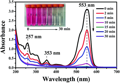
The oxidation mechanism of RhB by ˙OH has been studied in detail previously.43,44 It is recognized that two competitive processes occur simultaneously during the ˙OH attraction: the N-deethylation and destruction of the dye chromophore structure (a conjugated xanthene ring). In our case, there was no obvious shift in the characteristic absorption bands but a sharp reduction was observed as shown in Fig. 8, which proved that the decomposition of the conjugated xanthene ring was the dominant oxidation pathway for RhB. The open-ring reaction of the conjugated xanthene will generate a series of aromatic phenol intermediates, such as o-phenylphenol, 2,3-dihydroxybenzoic acid, 2,5-hydroxybenzoic acid, 3-hydroxybenzoic acid, (iso/tere)-phthalic acid and benzoic acid, which have been detected in the previous literature.43–47 These compounds were further degraded into smaller aliphatic acids and were eventually completely mineralized to CO2, which can be proved by the results of the TOC measurement. Moreover, some of the aromatic phenol intermediates such as o-phenylphenol and 2,3-dihydroxybenzoic acid are capable of forming polymers over the anode surface at a low anode potential such as 1.94 V vs. SCE. On the basis of all of the above experimental results and the previous studies, a simple schematic to describe the RhB oxidation process in the reactive electrochemical filter system in this study is given in Fig. 9.
3.6. Energy consumption
Energy consumption is an important factor to consider when evaluating the application prospects of the reactive electrochemical filter system with the porous Ti/SnO2–Sb filter developed in the present study for wastewater treatment. The electrical efficiency per log order degradation (EE/O, kW h m−3) of RhB was calculated to evaluate the economic feasibility of the reactive electrochemical filter system and is shown in Table 1. The energy demand of the reactive electrochemical filter system in flow-through mode increases with the increase in the applied anode potential, and the system in flow-through mode exhibited a much lower energy consumption than that in flow-by mode under the same conditions. The EE/O value was 0.28 kW h m−3 in flow-through mode at an anode potential of 2.18 V vs. SCE, which was only 11.43% of that in flow-by mode at an anode potential of 2.25 V vs. SCE (2.45 kW h m−3). The EE/O values were 0.21 kW h m−3 and 0.82 kW h m−3, respectively, at anode potential values of 1.94 V and 3.04 V vs. SCE in flow-through mode. Notably, the EE/O value was increased by 3.9 times, while the kRhB value was only enhanced by 2.25 times when the anode potential increased from 1.94 V to 3.04 V vs. SCE, indicating that a higher anode potential led to a lower energy efficiency. However, the evaluation of a system depends not only on the energy consumption, but also on the space efficiency. The residence time values (t90%) were 17.1 min, 9.8 min and 7.8 min at the anode potentials of 1.94 V, 2.18 V and 3.04 V vs. SCE, respectively. In view of the appreciable space efficiency and energy consumption, the anode potential of 2.18 V vs. SCE was a good choice due to the low energy consumption (0.28 kW h m−3, or 97.2 kW h per kg TOC at ∼44% TOC removal) and the relatively short residence time (9.8 min). The value of 97.2 kW h per kg TOC (equal to 36.4 kW h per kg COD in theory) was much lower than the value reported by Yang48 (101.34 kW h kg COD−1) who used a CNT flow-through reactor for the degradation of reactive Brilliant red X-3B (50 mg L−1) with ∼82% oxidation removal and ∼46% COD removal. Alternatively, the value of 0.28 kW h m−3 is comparative to the state-of-the-art electrochemical oxidation processes with energy consumptions in the range of 0.1–40 kW h m−3.284. Conclusions
The major conclusions drawn from this study are summarized as follows.(1) Tubular porous Ti/SnO2–Sb filters were prepared by a sol–gel method using low-cost powder sintered porous titanium filters with an average pore size of about 30 μm as the substrates. These porous Ti/SnO2–Sb filters exhibited excellent penetration fluxes (up to 61.94 m3 m−2 h−1 bar−1) and good electrochemical properties, such as high oxygen evolution potentials, electrochemical stability and high electro-active surfaces.
(2) A convection-enhanced rate constant for Fe(CN)64− oxidation of 4.35 × 10⁻⁴ m s−1 was achieved at a high penetration flux of 18.6 m3 m−2 h−1, which approached the kinetic limit and is the highest reported in a reactive electrochemical filter system. The results also suggested that for further improvement of the intrinsic kinetic reactivity of the reactive electrochemical filter system, it is necessary to design new electrode materials with higher specific electroactive surface area or roughness.
(3) The reactive electrochemical filter system in flow-through mode resulted in a 8.6-fold enhancement in the observed first-order rate constant for RhB oxidation (kRhB, min−1) relative to flow-by mode at an input current of 0.5 A (∼2.8 mA cm−2). RhB oxidation in flow-through mode reached an observed rate constant (kobs, RhB, m s−1) of 5.76 × 10⁻⁴ m s−1 at an anode potential of 3.04 V vs. SCE (∼8.5 mA cm−2), which is much higher than the highest rate constants reported in the literature to date (1.7 × 10⁻⁵–1.4 × 10⁻⁴ m s−1).
(4) The mineralization current efficiency in flow-through mode was more than one magnitude higher than that in flow-by mode under the same experimental conditions. Under an anode potential of 2.18 V vs. SCE, the electrical energy per order degradation (EE/O) for RhB was as low as 0.28 kW h m−3 in flow-through mode, with a relatively short residence time of 9.8 min. This value is comparative to the state-of-the-art electrochemical oxidation processes with energy consumptions in the range of 0.1–40 kW h m−3.
These anodic reactive electrochemical membranes, the porous Ti/SnO2–Sb filters, are low-cost and easy to mass-produce. In this study, we developed a reactive electrochemical filter system that is practical and can be implemented for large-scale industrial applications and has a high penetration flux, a high mass transfer rate and a strong electrooxidation performance. It is a promising technology for treating organics in wastewater. Further investigations into the toxicity as well as the effects of the matrix and operation parameters should be carried out before applying this technology to wastewater purification.
Conflicts of interest
The authors declare no competing financial interest.Acknowledgements
This study was financially supported by the National Natural Science Foundation of China (No. 21607006), the Special Financial Grant from the China Postdoctoral Science Foundation (No. 212400227), and the Guangdong Innovation Team Project for Colleges and Universities (No. 2016KCXTD023). The authors also acknowledge the support of the Sichuan Province Science and Technology Department (No. 2017HH0065).References
- G. Chen, Sep. Purif. Technol., 2004, 38, 11 CrossRef CAS.
- E. S. Z. El-Ashtoukhy, N. K. Amin and O. Abdelwahab, Chem. Eng. J., 2009, 146, 205 CrossRef CAS.
- H. Yu, Y. Li, M. Zhao, H. Dong, H. Yu, S. Zhan and L. Zhang, Catal. Today, 2015, 258, 156 CrossRef CAS.
- X. Li, Y. Wu, W. Zhu, F. Xue, Y. Qian and C. Wang, Electrochim. Acta, 2016, 220, 276 CrossRef CAS.
- E. Tsantaki, T. Velegraki, A. Katsaounis and D. Mantzavinos, J. Hazard. Mater., 2012, 207, 91 CrossRef PubMed.
- A. Fernandes, D. Santos, M. J. Pacheco, L. Ciriaco and A. Lopes, Sci. Total Environ., 2016, 541, 282 CrossRef CAS PubMed.
- F. C. Moreira, J. Soler, A. Fonseca, I. Saraiva, A. R. B. Rui, E. Brillas and V. J. P. Vilar, Appl. Catal., B, 2016, 182, 161 CrossRef CAS.
- J. Niu, H. Lin, J. Xu, H. Wu and Y. Li, Environ. Sci. Technol., 2012, 46, 10191 CAS.
- Q. Zhuo, M. Luo, Q. Guo, G. Yu, S. Deng, Z. Xu, B. Yang and X. Liang, Electrochim. Acta, 2016, 213, 358 CrossRef CAS.
- B. P. Chaplin, Environ. Sci.: Processes Impacts, 2014, 16, 1182 CAS.
- H. Lecher and W. Siefken, Electrochim. Acta, 2009, 54, 2018 CrossRef.
- A. Donaghue and B. P. Chaplin, Environ. Sci. Technol., 2013, 47, 12391 CrossRef CAS PubMed.
- L. Guo, Y. Jing and B. P. Chaplin, Environ. Sci. Technol., 2016, 50, 1428 CrossRef CAS PubMed.
- M. H. Schnoor and C. D. Vecitis, J. Phys. Chem. C, 2013, 117, 2855 CAS.
- A. Kitada, G. Hasegawa, Y. Kobayashi, K. Kanamori, K. Nakanishi and H. Kageyama, J. Am. Chem. Soc., 2012, 134, 10894 CrossRef CAS PubMed.
- S. E. Elsherif, D. B. Bejan and N. J. B. J Bunce, Can. J. Chem., 2010, 88, 928 CrossRef CAS.
- D. Bejan and N. J. Bunce, Can. J. Chem., 2012, 90, 666 CrossRef.
- G. S. Ajmani, D. Goodwin, K. Marsh, D. H. Fairbrother, K. J. Schwab, J. G. Jacangelo and H. Huang, Water Res., 2012, 46, 5645 CrossRef CAS PubMed.
- C. D. Vecitis, M. H. Schnoor, M. S. Rahaman, J. D. Schiffman and M. Elimelech, Environ. Sci. Technol., 2011, 45, 3672 CrossRef CAS PubMed.
- G. Gao and C. D. Vecitis, Environ. Sci. Technol., 2011, 45, 9726 CrossRef CAS PubMed.
- D. Li, J. Tang, X. Zhou, J. Li, X. Sun, J. Shen, L. Wang and W. Han, Chemosphere, 2016, 149, 49 CrossRef CAS PubMed.
- L. Zang, L. Xu, J. He and J. Zhang, Electrochim. Acta, 2014, 117, 192 CrossRef.
- M. Panizza and G. Cerisola, Chem. Rev., 2009, 109, 6541 CrossRef CAS PubMed.
- B. Adams, M. Tian and A. Chen, Electrochim. Acta, 2009, 54, 1491 CrossRef CAS.
- C. J. Miller, H. Yu and T. D. Waite, Colloids Surf., A, 2013, 435, 147 CrossRef CAS.
- M. F. Hou, L. Liao, W. D. Zhang, X. Y. Tang, H. F. Wan and G. C. Yin, Chemosphere, 2011, 83, 1279 CrossRef CAS PubMed.
- H. Lin, J. Niu, S. Ding and L. Zhang, Water Res., 2012, 46, 2281 CrossRef CAS PubMed.
- Y. Liu, H. Liu, Z. Zhou, T. Wang, C. N. Ong and C. D. Vecitis, Environ. Sci. Technol., 2015, 49, 7974 CrossRef CAS PubMed.
- Y. Bessekhouad, R. Brahimi, F. Hamdini and M. Trari, J. Photochem. Photobiol., A, 2012, 248, 15 CrossRef CAS.
- Z. Sun, H. Zhang, X. Wei, X. Ma and X. Hu, J. Solid State Electrochem., 2015, 19, 2445 CrossRef CAS.
- A. M. Zaky and B. P. Chaplin, Environ. Sci. Technol., 2014, 48, 5857 CrossRef CAS PubMed.
- W. Zhang, H. Kong, H. Lin, H. Lu, W. Huang, J. Yin, Z. Lin and J. Bao, J. Alloys Compd., 2015, 650, 705 CrossRef CAS.
- H. Vogt, Electrochim. Acta, 1994, 39, 1981 CrossRef CAS.
- S. Asim, J. Yin, X. Yue, M. W. Shah, Y. Zhu, Y. Li and C. Wang, RSC Adv., 2015, 5, 28803 RSC.
- N. D. Mu’Azu, M. H. Almalack and N. Jarrah, Desalin. Water Treat., 2014, 52, 7293 CrossRef.
- G. Zhao, X. Cui, M. Liu, P. Li, Y. Zhang and T. Cao, Environ. Sci. Technol., 2009, 43, 1480 CrossRef CAS PubMed.
- N. G. Tsierkezos and U. Ritter, J. Chem. Thermodyn., 2012, 54, 35 CrossRef CAS.
- R. Geng, G. H. Zhao, M. C. Liu and Y. Z. Lei, Acta Phys.-Chim. Sin., 2010, 26, 1493 CAS.
- J. Yang, J. Wang and J. P. Jia, Environ. Sci. Technol., 2009, 43, 3796 CrossRef CAS PubMed.
- L. Guo, Y. Jing and B. P. Chaplin, Environ. Sci. Technol., 2016, 50, 1428 CrossRef CAS PubMed.
- M. C. Santos, Y. A. Elabd, J. Yin, B. P. Chaplin and F. Lei, AIChE J., 2016, 62, 508 CrossRef CAS.
- R. Berenguer, J. M. Sieben, C. Quijada and E. Morallón, Appl. Catal., B, 2016, 199, 394 CrossRef CAS.
- S. Horikoshi, A. Aiko Saitou, H. Hidaka and N. Serpone, Environ. Sci. Technol., 2003, 37, 5813 CrossRef CAS PubMed.
- Y. Yu, S. Yang, H. He, C. Sun, C. Gu and Y. Ju, J. Phys. Chem. A, 2009, 113, 10024 CrossRef PubMed.
- T. S. Natarajan, M. Thomas, K. Natarajan, H. C. Bajaj and R. J. Tayade, Chem. Eng. J., 2011, 169, 126 CrossRef CAS.
- Z. He, C. Sun, S. G. Yang, Y. C. Ding, H. He and Z. L. Wang, J. Hazard. Mater., 2009, 162, 1477 CrossRef CAS PubMed.
- D. M. D. Araújo, C. Sáez, C. A. Martínez-Huitle, P. Cañizares and M. A. Rodrigo, Appl. Catal., B, 2015, 166, 454 CrossRef.
- J. Yang, J. Wang and J. P. Jia, Environ. Sci. Technol., 2009, 43, 3796 CrossRef CAS PubMed.
Footnote |
| † Electronic supplementary information (ESI) available. See DOI: 10.1039/c8ra00603b |
| This journal is © The Royal Society of Chemistry 2018 |

