 Open Access Article
The preparation, microstructure and mechanical properties of a dense MgO–Al2O3–SiO2 based glass-ceramic coating on porous BN/Si2N2O ceramics
Yangshan Sunab,
Delong Caiab,
Zhihua Yang *abc,
Hailiang Liab,
Quan Liab,
Dechang Jia*abc and
Yu Zhouab
aInstitute for Advanced Ceramics, School of Materials Science and Engineering, Harbin Institute of Technology, Building C3, No. 2 Yikuang Street, Nangang District, Harbin, Heilongjiang 150080, China. E-mail: dcjia@hit.edu.cn; zhyang@hit.edu.cn; Fax: +86 451 86414291; Tel: +86 451 86418792
bKey Laboratory of Advanced Structrual–Functional Integration Materials & Green Manufacturing Technology, Harbin Institute of Technology, Harbin, Heilongjiang 150001, China
cState Key Laboratory of Advanced Welding and Joining, Harbin Institute of Technology, Harbin, Heilongjiang 150001, China
First published on 15th May 2018
Abstract
A dense MgO–Al2O3–SiO2 based glass-ceramic coating was prepared by a doctor blade process on a porous BN/Si2N2O ceramic surface followed by heat treatment at 1050 °C under nitrogen flow. The phase composition, microstructure, mechanical properties and water absorption of the coating were studied. The coating consisted of α-cordierite phase with a small amount of glass phase. The dense coating without pores and cracks was favorable to seal and densify the porous ceramic surface due to part of the molten glass infiltrating the surface pores. The coating was defect-free and tightly bonded to the substrate because of a larger bonding area between the coating and the substrate. The elastic modulus and bending strength of the glass-ceramic coating were 37.9 GPa and 67.1 MPa, respectively. Moreover, the coated samples had a high Vickers hardness and low water absorption.
1. Introduction
Porous BN/Si2N2O ceramics are candidate structural/functional materials for high temperature wave transparent applications due to their low density, excellent thermal shock resistance, superior thermal stability and outstanding dielectric properties (ε < 4.49, tan![[thin space (1/6-em)]](https://www.rsc.org/images/entities/char_2009.gif) δ < 0.0056).1–3 Nevertheless, the high porosity lowers not only the flexural strength but also the erosion resistance of these ceramic composites and, because of the capillary force, the porous surface is easily filled with water molecules which condense into the hydration layer. The dielectric properties of porous nitride ceramics are extremely sensitive to water, and water has a high dielectric constant and loss tangent (ε = 76, tan
δ < 0.0056).1–3 Nevertheless, the high porosity lowers not only the flexural strength but also the erosion resistance of these ceramic composites and, because of the capillary force, the porous surface is easily filled with water molecules which condense into the hydration layer. The dielectric properties of porous nitride ceramics are extremely sensitive to water, and water has a high dielectric constant and loss tangent (ε = 76, tan![[thin space (1/6-em)]](https://www.rsc.org/images/entities/char_2009.gif) δ = 12, 25 °C).4 These problems can be resolved by applying a dense coating on the porous BN/Si2N2O ceramic surface to improve the hardness and water resistance of the substrate.
δ = 12, 25 °C).4 These problems can be resolved by applying a dense coating on the porous BN/Si2N2O ceramic surface to improve the hardness and water resistance of the substrate.
In previous studies, porous nitride ceramics have been improved in tightness by impregnation with resin or amorphous silica, for example SiC prepared by CVD, to fill the surface pores..5–7 All of these coatings can provide a tight film to prevent moisture from entering the porous ceramic and promote the flexural strength of the porous ceramic. However, these kinds of coatings have their shortcomings. The service temperature of the resin coating is low and sensitive to aging. Furthermore, its elevated temperature ablation will have carbon residue, which will deteriorate the wave transparent properties of the porous ceramic substrate.8–10 Previous research shows that the coefficient of thermal expansion (CTE) of amorphous silica (0.54 × 10⁻⁶ °C−1) is much lower than that of nitride ceramics (2.5–4.5 × 10⁻⁶ °C−1). The CTE mismatch between the amorphous silica coating and the nitride ceramic results in the formation of microcracks.11 Also, amorphous silica is thermodynamically unstable at temperatures above 1200 °C.12 As we know, it is paramount that the coating of porous ceramics must have excellent dielectric properties in order to meet the requirements for radomes. Thus, SiC is not suitable as a radome coating material due to its high dielectric constant and loss tangent. In fact, it is generally used as a wave absorbing material.13,14 In recent years, MgO–Al2O3–SiO2 (MAS) based glass-ceramics have attracted the attention of researchers due mainly to their outstanding properties, i.e. low dielectric constant and dielectric loss, excellent thermal shock resistance and positive high temperature oxidation resistance, and, in particular, the fact that their CTE can be adjusted by changing the ratio of ingredients.15–21 Until now, there have been few reports on the preparation of MAS based glass-ceramic coatings on the surface of porous nitride ceramics.
In this work, a dense MAS based glass-ceramic layer is prepared on the surface of a porous BN/Si2N2O ceramic through a doctor blade process, which is simpler and cheaper than traditional methods, i.e. chemical vapour deposition (CVD), plasma spray (PS) and electrophoretic deposition.22–24 The phase assemblage, microstructure and mechanical properties of the coating are investigated. This study serves as a reference for the selection and preparation of surface coatings for porous nitride ceramics and promotes the application of porous BN/Si2N2O ceramics as a radome material.
2. Experimental procedure
Porous BN/Si2N2O ceramics were fabricated by pressure-less sintering at 1650 °C in our previous work. Some of the properties of the porous BN/Si2N2O ceramic are presented in Table 1, and XRD on its surface showed the presence of Si2N2O and h-BN together with a small amount of β-Si3N4, as shown by curve (c) in Fig. 5.| Properties | Apparent porosity (%) | Elastic modulus (GPa) | Flexural strength (MPa) | Bulk density (g cm−3) |
|---|---|---|---|---|
| BN/Si2N2O | 28.4 | 100.7 ± 7.5 | 210.8 ± 15.3 | 2.10 |
The starting materials of the coating material are based on MgO (purity >98%, d = 5.83 μm), Al2O3 (purity >98%, d = 0.73 μm), fused quartz (purity >98%, d = 3.39 μm), and B2O3 (purity >98%, d = 74 μm). MgO, Al2O3, fused quartz and B2O3 were 20 g, 24 g, 56 g and 15 g, respectively. Powders of the oxides were mixed in a platinum crucible and melted at 1500 °C for 2 h in air, then quenched in distilled water to form glass frits. After quenching, the glass frits were extracted, crushed and then milled with alcohol for 8 h. The ground-glass powders were dried and sieved by a 120-mesh screen. XRD (D8ADVANCE, Bruker, Germany) detected that the powders were amorphous. Differential thermal analysis (DTA; STA449C, NETZSCH, Germany) was performed on a 50 mg sample of the powders heated in air from room temperature (RT) to 1200 °C, at 5 °C min−1, with an Al2O3 reference.
The green compacts of the MAS based glass-ceramic are formed by consolidating the glass powder into a disc of 60 mm in diameter at 30 MPa in a steel mould. After that, the green compacts are heat treated to obtain MAS based glass-ceramic blocks for the coefficient of thermal expansion (CTE; DIL402C, NETZSCH, Germany) test on samples of 4 mm × 4 mm × 20 mm at RT–900 °C. The slurry for the coating was 70 wt% glass powder together with 30 wt% organic solvents, and the components of the organic solvents included 81 wt% solvents (butyl carbitol), 4 wt% adhesives (ethyl cellulose), 10 wt% plasticizers (tributyl citrate) and 5 wt% surfactants (sorbitan trioleate) mixed evenly by ball-milling for 30 min. Then the slurry was applied on the as-received porous BN/Si2N2O ceramic surface via a doctor blade process. The doctor blade process works by placing a sharp blade at a fixed distance from the substrate surface. The coating solution is placed in front of the blade which is then moved linearly across the substrate, leaving a thin wet film after the blade.25 The decomposition of the organic solvents was conducted in a muffle oven at 450 °C for 2 h in air. Afterwards, the composites were heated in a tubular oven at 1050 °C for 1 h under nitrogen flow. The phase composition of the coating layer was determined by XRD. The microstructure of the coated composites was characterized by scanning electron microscopy (SEM, Quanta 200, FEI Co., USA). Energy dispersive spectroscopy (EDS, Hitachi, Tokyo, Japan) was utilized to analyze the elemental composition.
The elastic modulus and strength of the glass-ceramic coating are measured by the relative method.26 The Vickers hardness of the substrate and coated composite was measured on the polished surfaces under a load of 98 N with a dwell time of 10 s. Vickers micro-indentation was performed at the interface of the coated composite to qualitatively measure the presence of residual stresses at the interface. The adhesion strength of the coatings was measured using a universal testing machine at a cross head speed of 0.5 mm min−1 according to the GB8642-88 method. The water absorption of the uncoated and coated porous BN/Si2N2O ceramics was assessed by the Archimedes method using distilled water as the medium.
3. Results and discussion
3.1 Properties of glass powders
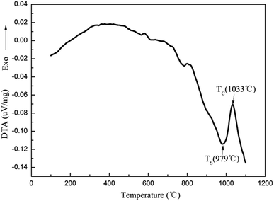
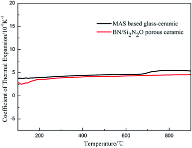
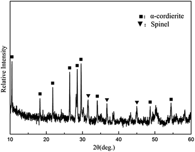
The composition of the coating material was chosen to obtain a glass-ceramic for the following three reasons. Firstly, the CTE values of glass-ceramics are very close to those of BN/Si2N2O porous ceramics. Secondly, cordierite is the main crystalline phase of glass-ceramics and possesses a low CTE value and favorable dielectric properties.27–29 Thirdly, the preparation temperature of the coating is below 1400 °C, which is to ensure that the mechanical properties of Si2N2O are not compromised.30For the preparation of the MAS based glass-ceramic, the sintering process should be based on the softening point (Ts) and the crystallization point (Tc) of the glass powder. So, for this glass composition, Ts (979 °C) and Tc (1033 °C) were measured by DTA as shown in Fig. 1. Then the MAS based glass-ceramic samples were fabricated by heating at 979 °C for 1 h and up to 1033 °C for 1 h. The XRD analysis indicated that the principal crystalline phase of the glass-ceramic was α-cordierite (Mg2Al4Si5O18) with a small amount of spinel (MgAl2O4) phase, as depicted in Fig. 3. Additionally, the CTE value of the glass-ceramic coating, which was difficult to measure, can refer to that of the glass-ceramic blocks. As shown in Fig. 2, the CTE values of the glass-ceramic blocks were very close to that of the BN/Si2N2O porous ceramic at 100–900 °C. Therefore, this glass composition can be selected as the composition of the coating on the BN/Si2N2O porous ceramic surface. The sintering temperature of the coating was chosen as 1050 °C, a temperature above Ts and Tc of this glass composition, to achieve an adequate low viscosity for homogeneous glass deposition or even for penetration into the substrate.
3.2 Phase compositions and microstructures of the coating
As shown in pattern (a) of Fig. 4, the dominant crystalline phase of the coating is α-cordierite, while some residual glass phase can be detected by XRD analysis. In this case, α-cordierite as the main crystal phase ensures that the CTE value of the coating is close to that of the matrix and that the coating has favorable dielectric properties. Meanwhile, a small amount of glass phase can have a role in promoting the adhesion of the coating and the matrix.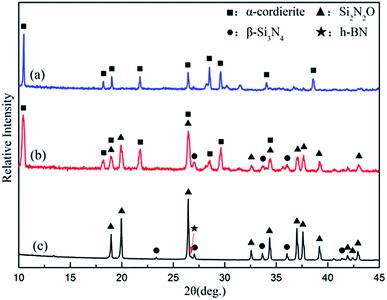 | ||
| Fig. 4 XRD patterns of the glass-ceramic coating (a), intersection regions between the coating and the substrate (b), and the BN/Si2N2O substrate (c). | ||
Fig. 5(a) shows SEM images of the BN/Si2N2O porous ceramic substrate surface. Obviously, the surface of the BN/Si2N2O substrate was porous and loose with an apparent porosity of 25.9% (Table 1). Fig. 5(b) and (c) indicate the original and polished surface of the coated sample. The resulting coating surface was dense without pores and cracks. The polished surface of the coating was also dense and flat, which can be seen from the coating area in Fig. 5(c). Meanwhile, part of the coating on the surface of the coated composite was ground down to expose the substrate material. There were no open pores that could be observed in the substrate area, and it was obviously denser than the original substrate surface shown in Fig. 5(a). This result showed that part of the softened glass powder of the coating could enter into the surface pores of the substrate during the sintering process, which led to the densification of the substrate surface. Therefore, the substrate surface pores can be effectively sealed by the as-prepared glass-ceramic coating.
 | ||
| Fig. 5 SEM images of the BN/Si2N2O porous ceramic substrate surface (a) and the original (b) and polished (c) surface of the coated sample. | ||
Furthermore, as seen from the cross section between the coating and the substrate, the morphology of the traces of the residual coating after grinding indicates that the coating was gradually worn out and there was no peel-off phenomenon during the grinding process. The phase composition of the cross sectional area was analyzed by a micro-area XRD test. As shown in pattern (b) of Fig. 4, the main crystal phases of the intersection regions were Si2N2O and α-cordierite, which were consistent with those of the substrate and coating.
Fig. 6 shows the cross-section SEM images and line-scanning EDS analysis of the coated composite. From Fig. 6(a), the main elements contained in the coating were Mg, Al, Si and O, which were consistent with the XRD analysis. The coating was homogeneous, and the coating/substrate interface was continued without a gap. This result implied that the coating material had good wettability and adhesion with the as-received BN/Si2N2O porous ceramic surface. At high magnification of the cross-section, as shown in Fig. 6(b), the coating was dense without pores and cracks, and no defects could be noted at the interface. Moreover, the interface was uneven due to part of the softened glass powder infiltrating the surface pores of the substrate, indicating that a rough and porous substrate surface increases the bonding area between the coating and the substrate. The thickness of this glass-ceramic coating was about 80–100 μm.
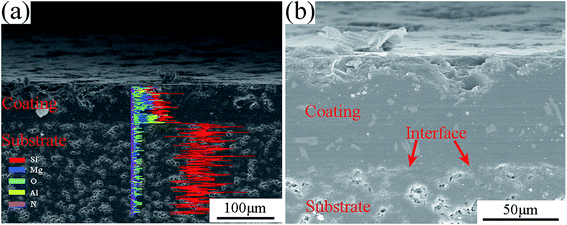 | ||
| Fig. 6 The cross-section SEM image and line-scanning EDS analysis of the coated composite, (a) line-scanning EDS analysis; (b) magnification of the cross-section. | ||
3.3 Mechanical properties and water resistance of the coating
In this paper, the prepared MAS based glass-ceramic coating is a single-face film. For a single-face coated composite, the elastic modulus of the film (Ef) is calculated by
 | (1) |
where h and H is the thickness of the film and substrate, respectively, and F is the deflection ratio. Obviously, the value of F is key for evaluating the practical modulus of the film. Here, F can be given in the moduli of the substrate and composite, using eqn (2)
 | (2) |
 | (3) |
 | (4) |
| No. | h (mm) | Ec (GPa) | Ef (GPa) | σc (MPa) | σf (MPa) |
|---|---|---|---|---|---|
| 1 | 0.08 | 96.3 | 38.5 | 180.6 | 70.1 |
| 2 | 0.09 | 95.5 | 34.9 | 178.4 | 63.0 |
| 3 | 0.10 | 95.4 | 39.9 | 185.4 | 74.7 |
| 4 | 0.08 | 96.9 | 46.7 | 161.2 | 76.0 |
| 5 | 0.10 | 94.5 | 29.7 | 171 | 51.6 |
| Average | 95.7 ± 0.9 | 37.9 ± 6.3 | 175.3 ± 9.4 | 67.1 ± 10.0 |
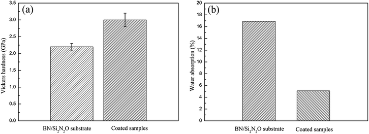
Vickers micro-indentation was performed with a load of 4.9 N at the coating/substrate interface, as shown in Fig. 7(a). There was a significant collapse at the indentation on the substrate side of the interface due to the porous structure of the substrate material. The formation and propagation of cracks were not observed, and the well-known spallation phenomena were not caused when the indentation occurred at the interface. The result revealed that the CTE value of the coating matched with that of the BN/Si2N2O porous ceramic substrate, and there were less residual stresses at the coating/substrate interface. The adhesion strength of the coatings was measured as about 5.9 MPa and Fig. 7(b) shows the micrograph of the fracture surface. It was evident that the substrate was not exposed and a portion of the coating was still attached to the substrate surface after the adhesion strength test, implying that the coating was well bonded to the substrate. This stems from the fact that the porous surface of the substrate provides a larger bonding area with the coating. The Vickers hardness and water absorption of the substrate and coated samples are shown in Fig. 8. The Vickers hardness was improved from 2.2 GPa to 3.0 GPa, and the water absorption declined significantly due to the formation of the dense coating.
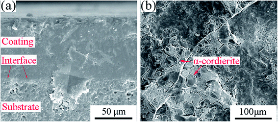 | ||
| Fig. 7 (a) Vickers micro-indentation at the interface of the cross-section; (b) micrograph of the fracture surface. | ||
4. Conclusions
MgO–Al2O3–SiO2 (MAS) based glass led to the development of a glass-ceramic coating for BN/Si2N2O porous ceramics by a doctor blade process. The resulting coating was an α-cordierite based glass-ceramic material, and it was dense and crack-free. Moreover, softened glass powder infiltrated the surface pores of the substrate, which increased the bonding area between the coating and the substrate. The coating/substrate interface was continuous without defects due to the good match of thermal expansion coefficients between the coating and the substrate. The glass-ceramic coating showed good mechanical properties and water resistance. As stated above, the MAS based glass-ceramic coating on the BN/Si2N2O porous ceramic surface exhibited a positive integrative performance, indicating that it could be a promising candidate for improving the moisture resistance, rain and particle erosion resistance of porous ceramic substrates.Conflicts of interest
There are no conflicts to declare.Acknowledgements
This work was supported by the National Natural Science Foundation of China (No. 51621091 and 51225203).References
- Q. Tong, Y. Zhou, J. Zhang, J. Wang, M. Li and Z. Li, Int. J. Appl. Ceram. Technol., 2008, 5, 295 CrossRef.
- S. J. Lin, F. Ye and J. Ma, Mater. Des., 2015, 87, 272 CrossRef.
- Y. Sun, Z. Yang and D. Cai, Ceram. Int., 2017, 43, 8230 CrossRef.
- J. Li, C. Zhang and S. Wang, Paint Coat. Ind., 2007, 37, 5 Search PubMed.
- T. Goto, A. Fujii and C. Kawai, Radome, US pat., US 6091375 A. 2000.
- H. T. Chiu, T. Sukachonmakul and T. K. Ming, Appl. Surf. Sci., 2014, 292, 928 CrossRef.
- X. Li, X. Yin and L. Zhang, Mater. Sci. Eng., A, 2009, 527, 103 CrossRef.
- R. Lambourne and T. A. Strivens, Paint and Surface Coatings-Theory and Practice, Woodhead Publishing, 2nd edn, 1999, pp. 1–18 Search PubMed.
- E. Leivo, T. Wilenius, T. Kinos, P. Vuoristo and T. Mäntylä, Prog. Org. Coat., 2004, 49, 69 CrossRef.
- P. Chevallier, M. Castonguay and S. Turgeon, J. Phys. Chem. B, 2001, 105, 12490 CrossRef.
- A. Kwatera and A. Sawka, J. Non-Cryst. Solids, 2000, 265, 120 CrossRef.
- X. Li, X. Yin and L. Zhang, J. Non-Cryst. Solids, 2008, 354, 3254 CrossRef.
- Y. Mu, W. Zhou and Y. Hu, J. Alloys Compd., 2015, 637, 261 CrossRef.
- F. Ye, L. Zhang and X. Yin, Appl. Surf. Sci., 2013, 270, 611 CrossRef.
- Z. Yue, J. Zhou and H. Zhang, J. Mater. Sci. Lett., 2000, 19, 213 CrossRef.
- S. Wang, H. Lu and Z. Hou, Ceram. Int., 2013, 39, 991 CrossRef.
- W. A. Zdaniewski, J. Am. Ceram. Soc., 1978, 61, 199 CrossRef.
- J. M. Wu and S. P. Hwang, J. Am. Ceram. Soc., 2000, 83, 1259 CrossRef.
- S. Mei, J. Yang and J. M. F. Ferreira, Mater. Lett., 2001, 47, 205 CrossRef.
- J. F. Wu, Z. Li, Y. Q. Huang, F. Li and Q. Yang, J. Alloys Compd., 2014, 583, 248 CrossRef.
- G. H. Chen and X. Y. Liu, J. Alloys Compd., 2007, 431, 282 CrossRef.
- T. J. Perham, L. C. Jonghe and W. J. Moberlychan, J. Am. Ceram. Soc., 1999, 82, 297 CrossRef.
- H. J. Allen, M. J. Lance, K. M. Cooley, M. K. Ferber and R. A. Lowden, J. Am. Ceram. Soc., 2000, 83, 657 Search PubMed.
- T. Damjanović, C. Argirusis and G. Borchardt, J. Eur. Ceram. Soc., 2005, 25, 577 CrossRef.
- F. C. Krebs, Sol. Energy Mater. Sol. Cells, 2009, 93, 394 CrossRef.
- Y. W. Bao, Y. C. Zhou, X. X. Bu and Y. Qiu, Mater. Sci. Eng., A, 2007, 458, 268 CrossRef.
- J. Banjuraizah, H. Mohamad and Z. A. Ahmad, J. Alloys Compd., 2009, 482, 429 CrossRef.
- Z. Li, J. Wu, L. Song and Y. Huang, J. Eur. Ceram. Soc., 2014, 34, 3981 CrossRef.
- L. Song, J. Wu, Z. Li, X. Hao and Y. Yu, J. Non-Cryst. Solids, 2015, 419, 16 CrossRef.
- M. Ohashi, S. Kanzaki and H. Tabata, J. Am. Ceram. Soc., 1991, 74, 109 CrossRef.
| This journal is © The Royal Society of Chemistry 2018 |

