 Open Access Article
Creative Commons Attribution 3.0 Unported Licence
Iron encapsulated in single-walled carbon nanotubes for obtaining the evidence of improved coulombic efficiency and improving the lithium battery performance of ZnO anodes†
Jiaxin Li abcd,
Mingzhong Zoucd,
Weijian Huangcd,
Chuxin Wuab,
Yi Zhao
 ab,
Lunhui Guan
 *ab and
Zhigao Huang
 *cd
*cd
aCAS Key Laboratory of Design and Assembly of Functional Nanostructures, Fujian Institute of Research on the Structure of Matter, Chinese Academy of Sciences, Fuzhou, Fujian 350002, P. R. China
bFujian Provincial Key Laboratory of Nanomaterials, Fujian Institute of Research on the Structure of Matter, Chinese Academy of Sciences, Fuzhou, Fujian 350002, P. R. China. E-mail: guanlh@fjirsm.ac.cn; Fax: +86 591 83792835; Tel: +86 591 83792835
cCollege of Physics and Energy, Fujian Normal University, Fujian Provincial Key Laboratory of Quantum Manipulation and New Energy Materials, Fuzhou, 350117, China. E-mail: zghuang@fjnu.edu.cn; Fax: +86 591 22867577; Tel: +86 591 22867577
dFujian Provincial Collaborative Innovation Center for Optoelectronic Semiconductors and Efficient Devices, Xiamen, 361005, China
First published on 23rd March 2018
Abstract
Cycling coulombic efficiency including the 1st cycle is a crucial factor for nano-carbon based anodes. How to improve their coulombic efficiency and further prove whether the additional reversible capacity produced from the SEI film in the 1st cycle is an obstacle for their possible commercial application in Li ion batteries (LIBs). For this aim, a novel composite of Fe-encapsulated single-walled carbon nanotubes (Fe@SWNTs) with special nano-structure was designed and used as an anode material for LIBs. The resulting Fe@SWNT anode can provide much larger coulombic efficiency of 53.1% in the 1st cycle than 35.6% for pure SWNTs, implying the value increment reached ∼50%. The Fe@SWNTs can exhibit an reversible capacity of 420 mA h g−1 after 300 cycles and excellent rate performance at room temperature, being obviously better than 275 mA h g−1 for a SWNT anode. The origination of this extra improved reversible capacity can be confirmed to be derived from the reversible reaction of SEI film activated by the Fe catalyst. Meanwhile, the Fe@SWNT anodes exhibited superior low-temperature (at 5 and −15 °C) electrochemical performance, which should be associated with an improved effect of the highly conducting Fe at low temperature, and with the activation of catalyst Fe on the reversible capacity. In addition, when Fe@SWNTs were developed as carriers for attaching ZnO, the ZnO/Fe@SWNTs can deliver much better LIB performance than anodes of pure ZnO and ZnO/SWNTs. Thus, catalyst modification supplied a promising route to obtain improved coulombic efficiency and reversible capacity for LIB nano-carbon based anodes.
1. Introduction
Nowadays, lithium ion batteries (LIBs) are under intensive research and development, as they are characterized by promising theoretical gravimetric and volumetric energy.1,2 Though commercial graphite has been developed with improved performance, its power density is still too low to meet the increasingly growing demand for high-level applications for LIBs.2,3 As expected, anodes of nano-materials, especially for nano-carbon materials with good conductivity, beneficial for Li+ transfer, have been believed to be promising anode materials for LIBs.4,5 However, the irreversible capacity loss in the 1st discharge, the poor coulombic efficiency and the relatively low capacity for anodic nano-carbon materials hampers their high-level applications in LIBs.5,6 It is of vital importance to effectively overcome these issues for anodic nano-carbon materials.Recently, several useful strategies have been proposed to overcome this obstacle, including the utilization of conductive metal nanoparticles covered on the materials and the utilization of metal catalysts attached on the surface of nano-carbon anode materials.7–18 As a typical example, Zhou's group reported that anode of carbon materials loaded with nano-sized metal catalyst can reduce some solid electrolyte interphase (SEI) components and further improve their reversible capacities.9,10 They certified that anodes of Ni nanoparticles (NPs) highly dispersed in N-containing carbon nanosheets can afford an unexpected reversible capacity of 1051 mA h g−1 after 30 cycles and 635 mA h g−1 after 100 cycles at the current density of 200 mA g−1.9 Subsequently, iron carbide (Fe3C) has attracted interests of researchers in LIBs due to its high catalytic activity, sufficient thermal stability and extreme hardness.10,11 Some recent reports also revealed that nano-carbon anodes containing composites of Fe3C can reduce some SEI components and further improve the reversible capacities for LIBs.12–16 Our group previously reported that the novel composites of Fe/Fe3C–CNFs can exhibit a high reversible capacity at room temperature, and deliver a high capacity of 250 mA h g−1 at 400 mA g−1 even after 55 cycles at a low temperature of −15 °C.17 The superior electrochemical performance of the Fe/Fe3C–CNF anodes is associated with the synergistic effect of the catalytic effect of Fe3C and the highly conducting Fe at low temperature. Especially, it is recently reported that Fe3C possessing good catalytic activity can prompt anodes of Fe3O4@Fe3C–C yolk–shell nanospindles to obtain excellent LIB performance.18 It is believed that the present Fe3O4@Fe3C–C yolk–shell nanospindles are the most efficient Fe3O4-based anode materials ever reported for LIBs. Subsequently, an important question comes around, how to prove whether the additional capacity derived from the reversible reaction of SEI film is desired for nano-material anodes.
It is generally recognized that single-walled carbon nanotubes (SWNTs) with unique structure have attracted considerable interest of scientists.19–23 In particular, SWNTs have been proven to be a good nano-vessel for investigating confined reaction.19–23 Besides, confined iron NPs have become of great interest in catalytic energy conversion and storage due to its thermal stability and catalytic activity.24,25 Based on the above discussion, the remarkable characteristics of a nano-vessel structure for SWNTs and the confined iron NPs motivated us to find out whether we can rationally design an encapsulated structure of Fe-based nanomaterials with sufficient catalytic activity for LIBs, and further provide evidence for proving the above mentioned hypothesis.
In this paper, we attempt to introduce nano-sized iron particles in SWNTs via a simple vapor phase method coupled with heat treatment and form a special hybrid material of Fe@SWNTs, with the aim of proving its electrochemical mechanism for LIBs. With the iron filling, Fe@SWNT anodes exhibited obviously better LIB performance including low-temperature performance compared with the pure SWNTs. Importantly, the result proves that the additional capacity produce from the reversible reaction of SEI film. In addition, we preliminarily used them as high performance carriers for ZnO NPs, forming ZnO/Fe@SWNT anodes. The reversible capacity of ZnO/Fe@SWNTs (containing 65 wt% ZnO) remains ∼575 mA h g−1 measured at 600 mA g−1 after 150 cycles, much better than those of ZnO NPs attached on carrier of pure SWNTs.
2. Experimental part
2.1. Materials synthesis
In this work, all chemicals were of analytical grade and used as received. The details of preparation for SWNTs and ferrocene@SWNTs (Fc@SWNTs) were presented in our earlier work.19–21 A single process was adopted to prepare Fe@SWNTs. The as-prepared Fc@SWNTs were annealed in a Ar flow at 500 °C for 1 h with a heating rate of 5 °C min−1 for forming Fe@SWNT composite. Fe particles outside of the SWNTs were removed by through washing in acid solution. The weight of Fe@SWNTs after washing is about 1.25 times greater than that of the empty SWNTs after encapsulation of Fe. Herein, the additional illustration for electrodes used for Raman test was presented in the ESI.†The typical preparation of ZnO/SWNT or ZnO/Fe@SWNT composites is given as follows. The SWNTs or Fe@SWNTs were treated with concentrated HNO3 (16 mol L−1) in 140 °C for 14 h. The composites were prepared using Zn(CH3COO)2·2H2O and KOH as the starting materials. 40 mg Zn(CH3COO)2·2H2O was dissolved in 50 mL anhydrous ethanol, following which 56 mg KOH was dispersed in the as-prepared solution by ultrasonification for 15 min in ice-water bath. A stable and optically transparent ZnO solution was consequently obtained and further stirred for 12 h. And then, 50 mg Fe@SWNTs of 40 mg SWNTs were respectively added to the ZnO solution and ultrasonicated for 0.5 h. The black solution obtained was then stirred for 24 h at 30 °C. Next, 0.44 g Zn(CH3COO)2·2H2O was added and stirred under a given condition. The final products were collected by filtration, washed by deionized water and ethanol, and finally dried at 60 °C in air for 24 h.
2.2. Materials characterization
The structure and morphology of the samples were characterized by X-ray diffraction (XRD, RIGAKU SCXmini), X-ray photoelectron spectroscopy, scanning electron microscope (SEM, JSM-6700F), transmission electron microscope (TEM, Tecnai G2 F20), X-ray photoelectron spectroscopy (XPS, ESCALAB 250) and Raman spectroscopy (Renishaw, excited at 785 nm), respectively.2.3. Electrochemical measurements
The electrochemical behaviors were measured via CR2025 coin-type test cells assembled in a dry argon-filled glove box. The test cell consisted of working electrode (∼1.5 mg cm−2) and lithium sheet which were separated by a Celgard 2300 membrane and electrolyte of 1 M LiPF6 in EC![[thin space (1/6-em)]](https://www.rsc.org/images/entities/char_2009.gif) :
:![[thin space (1/6-em)]](https://www.rsc.org/images/entities/char_2009.gif) EMC
EMC![[thin space (1/6-em)]](https://www.rsc.org/images/entities/char_2009.gif) :
:![[thin space (1/6-em)]](https://www.rsc.org/images/entities/char_2009.gif) DMC (1
DMC (1![[thin space (1/6-em)]](https://www.rsc.org/images/entities/char_2009.gif) :
:![[thin space (1/6-em)]](https://www.rsc.org/images/entities/char_2009.gif) 1
1![[thin space (1/6-em)]](https://www.rsc.org/images/entities/char_2009.gif) :
:![[thin space (1/6-em)]](https://www.rsc.org/images/entities/char_2009.gif) 1 in volume). The working electrode consisted of 80 wt% active material, 10 wt% carbon black and 10 wt% polymer binder (carboxymethyl cellulose, Na-CMC). The electrodes were dried at 100 °C for 12 h in a vacuum. Cyclic voltammetry tests were operated on a CHI660D Electrochemical Workstation with a scan rate of 0.50 mV s−1. The cells were cycled by LAND 2001A at room temperature and different low temperatures. Electrochemical impedance measurements were carried out by applying an ac voltage of 5 mV over the frequency range from 1 mHz to 100 kHz.
1 in volume). The working electrode consisted of 80 wt% active material, 10 wt% carbon black and 10 wt% polymer binder (carboxymethyl cellulose, Na-CMC). The electrodes were dried at 100 °C for 12 h in a vacuum. Cyclic voltammetry tests were operated on a CHI660D Electrochemical Workstation with a scan rate of 0.50 mV s−1. The cells were cycled by LAND 2001A at room temperature and different low temperatures. Electrochemical impedance measurements were carried out by applying an ac voltage of 5 mV over the frequency range from 1 mHz to 100 kHz.
3. Results and discussion
As observed from Fig. 1(a), the SWNTs appear as 20–80 nm bundles with part appearing as individuals. The Fig. 1(c) reveals that the typical diameter of a SWNT is ∼1.4 nm and the two parallel dark lines correspond to the SWNT walls. After encapsulating with iron particle, Fig. 1(b) displays the same bundle structure for Fe@SWNTs. Compared with Fig. 1(c), Fig. 1(d) clearly shows that segmented dark objects aligned linearly along the tube axis of SWNTs are attributed to iron particles. The other HR-TEM and SEM images for Fe@SWNTs have been shown in Fig. S1 and S2.† Fig. 1(e) compared the XRD patterns of SWNTs and Fe@SWNTs. The peak at 5.8° marked with an asterisk, which was ascribed to hexagonally packed SWNTs, disappeared in Fe@SWNTs because of the contribution of the reduced structure factor of Fe particles inside the tube. The result confirms that the Fe particles filled the tubes of the SWNTs. This result is also supported by the Raman test shown in Fig. 1(f). Fig. 1(f) shows the Raman spectra of the SWNTs and Fe@SWNTs with the excitation wavelength of 785 nm. The insets show the enlarged radial breathing mode (RBM) and G regions. With Fe encapsulation, both RBM and G bands shifted slightly because of the charge transfer between Fe and host SWNTs. The G band of the Fe@SWNTs downshifted from 1597.2 cm−1 to1593.2 cm−1, and the G′ band became broaden, indicating that the intercalation of Fe molecules into SWNTs leads to n-doping. These results can provide the improved conductivity for SWNT carrier caused by Fe dopant and further enhance their lithium battery performance.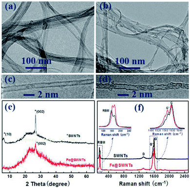 | ||
| Fig. 1 TEM and HR-TEM images of (a and c) SWNTs and (b and d) Fe@SWNTs; (e) XRD patterns of SWNTs and Fe@SWNTs; (f) Raman spectra of SWNTs and Fe@SWNTs. | ||
Fig. S3† shows the XPS spectra of Fe@SWNTs and pure SWNTs. From the Fe2p XPS spectra shown in Fig. S3(b),† it is evident that metallic iron (Fe0) at 707.5 eV is present in the as-prepared composites. The Fe2p3/2 peaks at 724.2, 719.8 and 710.8 eV are unique peaks for ferric irons, implying that iron has an affinity to bind to the carbon wall in SWNTs.13,15 The result is consistent with the C1s and O1s spectra shown in Fig. S4.† As expected, in the comparison of C1s for pure SWNTs and Fe@SWNTs shown in Fig. S4(a) and (c),† a typical sp2 C–C peak at 284.5 eV along with a sp3 C![[double bond, length as m-dash]](https://www.rsc.org/images/entities/char_e001.gif) C peak at 285.2 eV indicated in both samples are from the carbon layers in SWNTs, and the appearance of peak at 283.5 eV in the Fe@SWNT sample can be attributed to the electron transfer from nano iron to SWNTs. In addition, as revealed in the O1s XPS spectra in Fig. S4(b) and (d),† peaks of the O1s spectra for both Fe@SWNTs and pure SWNTs are similar. Anyhow, combined with the XRD analysis in the manuscript, these results indicate that most iron species exist as metallic Fe.
C peak at 285.2 eV indicated in both samples are from the carbon layers in SWNTs, and the appearance of peak at 283.5 eV in the Fe@SWNT sample can be attributed to the electron transfer from nano iron to SWNTs. In addition, as revealed in the O1s XPS spectra in Fig. S4(b) and (d),† peaks of the O1s spectra for both Fe@SWNTs and pure SWNTs are similar. Anyhow, combined with the XRD analysis in the manuscript, these results indicate that most iron species exist as metallic Fe.
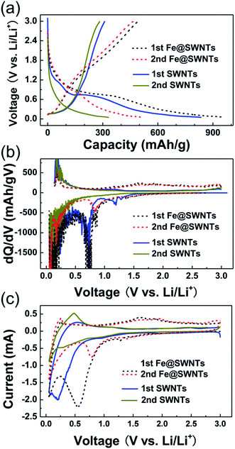
Electrochemical lithium storage properties of Fe@SWNTs and SWNTs were valuated as anode materials for lithium batteries in half-cell configurations and shown in Fig. 2. From Fig. 2(a), the 1st discharge/charge (D/C) curves of SWNT anode deliver capacities of 302 and 845 mA h g−1, indicating a coulombic efficiency of ∼35.6%. In contrast, the first D/C capacities for the Fe@SWNT anode were 505 and 949 mA h g−1, with a larger coulombic efficiency of ∼53.1% compared with the SWNTs. Thus, the 1st coulombic efficiency of pure SWNTs can be obviously increased by the encapsulation of catalyst of nano-sized iron, which value reached ∼50% (i.e., ∼50% = (53.1% − 35.6%)/35.6%). In addition to the enhancement of the 1st coulombic efficiency, to confirm the origination of this extra improved reversible capacity is of vital importance.
In addition, the first two D/C curves of Fe/Fe3C–CNFs are quite different from the pure CNFs. To better understand the redox reactions, differential capacity versus voltage (dQ/dV) curves of the first two cycles are investigated in Fig. 2(b). The curves clearly show redox peaks that correspond to the insertion or extraction of Li ions shown in Fig. 2(a). At the first discharge for SWNTs, a broad peak was observed at ∼0.70 V, corresponding to the starting formation of SEI film. This peak greatly decreased at the 2nd cycle, revealing the irreversible formation of SEI components. The following peak from 0.40 to 0.05 V and the extraction peaks around from 0.10 to 0.50 V in the charge were attributed to the Li insertion and extraction in/from trigonal interstitial channels and bundle pores of pure SWNTs, but not their inner channels. The related discussion was displayed in detail in Fig. S5 and S6.† Herein, being similar to SWNTs, the Li cannot insert/extract in/from the inner channels for Fe@SWNTs. However, from the curves of the Fe@SWNTs, the reduction peaks found from 1.30 to 0.80 V in the 1st cycle also appear in the 2nd cycle, implying the formation of reversible SEI films and the additional sites for Li intercalation. In addition, a broad oxidation peak located from 1.20 to 2.20 V being obviously more pronounced in Fe@SWNTs compared with SWNTs, is related to the Li extraction from SEI films and the partial polarization effect. Furthermore, the CVs repeatedly emerged at the same potentials for these two anodes revealed the similar mechanism compared with the dQ/dV curves. The CVs between 0.05 and 3 V of Fe@SWNTs and SWNTs at room temperature of 25 °C are shown in Fig. 3(c). In addition to the first two CV cycles, the redox peaks at the 3rd–8th cycles almost overlap with each other, also indicating the reversible oxidation of some SEI components and good cycling stability (see the additional CVs in Fig. S7†). Based on the above discussion combined with the Raman evidence shown in Fig. S5 and S6,† we attribute the excess Li capacity and distinct redox peaks observed in the Fe@SWNT anodes to Li insert/extract in/from the reversible SEI components. Thus, the nano-sized iron metal encapsulated in SWNTs as catalysts can reduce some SEI components and obviously enhance the lithium battery capacity.
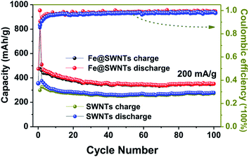 | ||
| Fig. 3 The cycling performance and coulombic efficiency of the Fe@SWNT and SWNT anodes at a current density of 200 mA g−1. | ||
The comparison of the cycling performance of the Fe@SWNTs and SWNTs at a current density of 200 mA g−1 was shown in Fig. 3. Apparently, the Fe@SWNTs exhibited a significantly improved reversible capacity. The reversible capacities for these two samples maintain stable with the increasing cycle number up to the 100th cycle. Herein, the reversible capacity of pure SWNTs only remained at ∼275 mA h g−1, while that of ∼375 mA h g−1 for the Fe@SWNTs, still being similar to the theoretical capacity of commercial graphite of 372 mA h g−1. As described in the experimental part, the mass content of Fe in the Fe@SWNTs are ∼17 wt%. Thus, subtracting the contribution from the SWNTs in Fe@SWNT composite, a reversible capacity of ∼863 mA h g−1 can be attributed to the additional capacities from SEI film, indicating the good catalytic effect from Fe encapsulation. Herein, the calculated capacity of 863 mA h g−1 is based on the following equation: [CFe@SWNTs − (CSWNTs × 83 wt%)]/17 wt% = [375 − (275 × 0.83)]/0.17 = 863. Besides to the reversible capacity and the 1st coulombic efficiency discussed at the above part, the coulombic efficiency in the following cycles for Fe@SWNTs of ∼99.3% are larger than of 97.8% for pure SWNTs, which indicating an important lithium battery factor for possible commercial research. The enhanced result is similar to the other recent reports.26–28
For the Fe@SWNT anodes, the further test of the long cycling and rate performance under different current densities have been carried out and displayed in Fig. 4. From Fig. 4(a), the cycle performance tested at relatively high current densities of 600 mA g−1 after being activated at 200 mA g−1 in the first three cycles. This anode can deliver reversible capacities of ∼300 mA h g−1 tested at 200 mA g−1 and 395 mA h g−1 tested at 600 mA g−1 for 197 and 95 cycles, respectively. Moreover, each fairly stable capacity at different current densities from 200 to 1200 mA g−1 can be observed in Fig. 4(b). When the current was reduced back to 200 mA g−1, the Fe@SWNTs can still deliver a reversible capacity of ∼390 mA h g−1, implying the good rate stability. These results indicate a good long cycling and rate performance. Furthermore, the long cycling and rate performance for pure SWNTs under the same tested condition of Fe@SWNTs have been carried out and compared in Fig. S8 and S9.† The results still revealed that the SWNTs with Fe encapsulation can provide better LIB performance including the coulombic efficiency especially for the 1st cycle, cycling stability, reversible capacity and rate cycling properties.
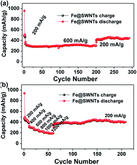 | ||
| Fig. 4 The long cycling performance and the rate cycling performance of the Fe@SWNT anodes at different current densities. | ||
As we know, the charge-transfer resistance for metal materials would decrease obviously with decreasing the temperature.7,13,29 Furthermore, to prove whether the improved effect of Fe@SWNTs on their LIB performance can remain in low temperature is also of vital importance. Thus, it is interesting and desired to investigate the low-temperature LIB performance for the Fe@SWNT anodes. Fig. 5(a) and (c) show the LIB performance of the SWNT and Fe@SWNT anodes under 5 and −15 °C at different current densities. Each fairly stable capacity tested from 150 to 450 mA g−1 can be observed. When the current was reduced back to 150 mA g−1, the Fe@SWNTs can still deliver reversible capacities of ∼283 and 142 mA h g−1 under 5 and −15 °C, being better than ∼172 and 47 mA h g−1 for pure SWNT anodes respectively. Therefore, with the decrease of tested temperature, the Fe@SWNTs shows a capacity loss of ∼49% (i.e., (142 − 283)/283 = 49%). By contrast, the SWNTs show a much larger capacity loss of ∼73%. For further evaluating the enhanced LIB performance for SWNTs with Fe encapsulation, the electrochemical impedance measurements were carried out at 5 and −15 °C after test and shown in Fig. 5(b) and (d). From Fig. 5(b), the difference of total resistance at 5 °C between SWNT and Fe@SWNT anodes are several hundreds of ohm. It is further to interestingly find that this difference increased sharply to several thousands of ohm when the temperature reduced to −15 °C as revealed in Fig. 5(d). As expected, the SWNTs demonstrate a more deteriorated resistance tested at lower temperature without Fe encapsulation. These results indicated that the presence of Fe encapsulation can significantly improve the conductivity and charge transfer resistance for Fe@SWNTs especially at a low temperature, and further enhance their LIB performance.
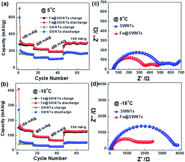 | ||
| Fig. 5 The cycling performance and the corresponding electrochemical impedance spectra of the SWNT and Fe@SWNT anodes: (a and c) 5 °C and (b and d) −15 °C. | ||
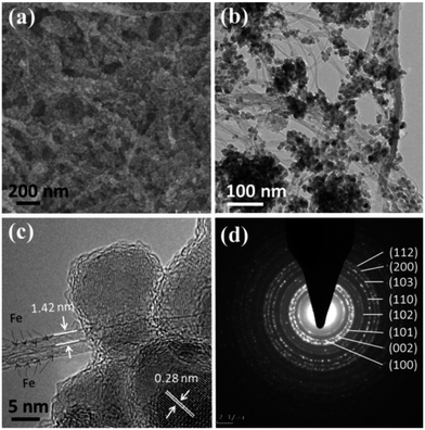
To investigate the enhanced effect of Fe@SWNT carriers for anodes, we preliminarily synthesis the composite of ZnO/Fe@SWNTs and study their LIB performance. The morphology and structure have been characterized by SEM, TEM and SAED, as shown in Fig. 6. As can be seen from Fig. 6(a), the ZnO NPs were coated well on the surface of Fe@SWNTs. The TEM image of Fig. 6(b) also supports this result. The covering of uniform ZnO NPs and typical bundles of Fe@SWNTs can be clearly observed. Fig. 6(c) further shows a HR-TEM image of ZnO/Fe@SWNTs. Being similar to the Fig. 1(d), the typical diameter of the SWNTs can be clearly found to be ∼1.4 nm, and the encapsulated iron filler can also be clearly determined. The existence of iron element was also supported by the EDS result shown in Fig. S9.† Meanwhile, two adjacent planes of ∼0.28 nm corresponding to the interlayer spacing of the (100) plane of ZnO was shown in figure. The samples of ZnO/SWNTs and ZnO/Fe@SWNTs were characterised and compared by XRD in Fig. S10.† The peak at 26° is ascribed to the (002) graphitic plane in SWNTs. All of other eight diffraction peaks could be unambiguously assigned to the zincite (ZnO) (JCPDS card no. 36-1451).30,31 These results are in consonance with that SEAD analysis. The detailed diffraction rings were presented in Fig. 6(d). Eight diffraction rings, respectively corresponding to the (103), (110), (102), (101), (002), (100), (200) and (112) planes of ZnO, can be observed clearly. In order to confirm the loading ratios of ZnO, SWNTs and Fe@SWNTs in composites, these two composite was used for TG analysis as shown in Fig. S11.† From the TGA curves, the weight ratio of the ZnO in ZnO/SWNTs and ZnO/Fe@SWNTs are ∼58.4 wt% and ∼56.1 wt%, respectively.
The Fig. 7 compared the cycling performance and the rate cycling performance of the ZnO/SWNT and ZnO/Fe@SWNT anodes at different current densities. Herein, Fig. S12a and b† show the discharge/charge voltage profiles of the ZnO/SWNT and ZnO/Fe@SWNT anodes. Equating to the CVs, the differential capacity versus voltage (dQ/dV) curves of the first two cycles are investigated in Fig. S12c and d.† The related electrochemical redox mechanism has been discovered for Fig. S12c and d, as shown in ESI.† As displayed in Fig. S13,† the two samples were tested at current densities of 200 mA g−1. Apparently, the ZnO/Fe@SWNTs exhibited a significantly improved reversible capacity. Meanwhile, these two samples were also tested at current densities of 600 mA g−1 after activating at 200 mA g−1 in the first three cycles as shown in Fig. 7(a). As expected, the ZnO/Fe@SWNT anode demonstrates an obviously better LIB cycling stability than that of without Fe encapsulation. The anode of ZnO/Fe@SWNTs can deliver discharged capacity of ∼575 mA h g−1 after 150 cycles at 600 mA g−1, showing a relative stable cyclability. However, the discharge capacity fade presented after the 60th cycle, remaining at only ∼195 mA h g−1 after 150 cycles. From Fig. 7(b), when the tested current densities increased from 200 mA g−1 to 1200 mA g−1, the initial reversible capacity of ∼720 mA h g−1 for ZnO/Fe@SWNT anode decreased to ∼545 mA h g−1, showing a difference of 175 mA h g−1. Under the same condition, the reversible capacity for ZnO/Fe@SWNT anode decreased from ∼583 to ∼316 mA h g−1, delivering a larger capacity fade of 267 mA h g−1 compared to ZnO/Fe@SWNT anode. More importantly, as the current density returned to 200 mA g−1, the ZnO/Fe@SWNT anode delivered a high capacity of ∼725 mA h g−1 even after 150 cycles, being much better than that of ∼335 mA h g−1 for the ZnO/SWNT anode. Interestingly, as calculated in the TGA result, the ZnO/SWNTs and ZnO/Fe@SWNTs contain ∼58.5 and ∼56 wt% ZnO, respectively. Thus, based on the Fig. 3 and S13,† subtracting the contribution from Fe@SWNTs in ZnO/Fe@SWNT nanocomposite, a reversible capacity of 958 mA h g−1 can be attributed to ZnO, indicating 98% of the theoretical capacity of ZnO (978 mA h g−1). By measuring at 200 mA g−1, the capacity of 958 mA h g−1 and the ratio of 98% can be calculated by the following equations: [CZnO/Fe@SWNTs − CFe@SWNTs × (44.0 wt%)]/56.0 wt% = [700 − (375 × 0.44)]/0.56 = 958 and 958/978 = 98%. The reversible capacity of ZnO in ZnO/Fe@SWNT nanocomposite can almost achieve its theoretical capacity under low current densities in this current study. The lithium battery performance presented in this work is comparable to the related reports.30–33 It is concluded that the electrochemical performance of in ZnO/Fe@SWNT nanocomposite composite can be strongly improved by using Fe@SWNTs as supporting carriers and catalysts.
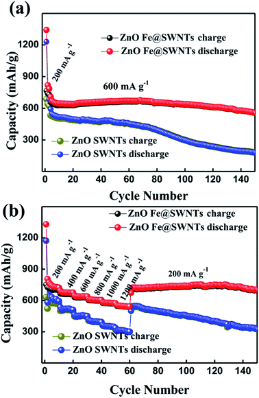 | ||
| Fig. 7 The cycling performance and the rate cycling performance of the ZnO/SWNT and ZnO/Fe@SWNT anodes at different current densities. | ||
Furthermore, from Fig. S14,† the cycle performance tested at relatively low temperature of 5 °C and at relatively high current densities of 1000 mA g−1 after being activated at 200 mA g−1 in the first three cycles. This anode can deliver reversible capacities of ∼330 mA h g−1 tested at 1000 mA g−1 even for 1400 cycles, revealing the excellent long cycling performance at low temperature. It is also concluded that the presence of Fe encapsulation can significantly improve the conductivity and charge transfer resistance for ZnO/Fe@SWNTs, being beneficial for bearing varied cycling currents. These results revealed that the ZnO/Fe@SWNT anode with good conductivity during the cycling process, which conclusion was also proved by the EIS result as shown in Fig. S15.†
4. Conclusions
In summary, to obtain the improved coulombic efficiency has become the key topic for LIB anodes of nano-carbon materials. As a typical sample, the novel composites of Fe-encapsulated single-walled carbon nanotubes (Fe@SWNTs) were synthesized via a simple vapor phase method coupled with heat treatment. Then the nano-structure Fe@SWNTs can be obtained and used as anode materials for LIBs. The resulting Fe@SWNT anode can provide much larger coulombic efficiency of 53.1% in the 1st cycle than 35.6% for pure SWNTs, implying the value increment reached ∼50%. Meanwhile, compared with pure SWNT anodes, the Fe@SWNTs can exhibit much better LIB performance both at room temperature and low temperatures of 5 and −15 °C. Importantly, the origination of this extra improved reversible capacity has been confirmed to be derived from the reversible reaction of SEI film activated by the catalyst. This preliminary work provides a useful strategy to obtain improved coulombic efficiency and reversible capacity nano-carbon anodes for high performance LIBs. Moreover, the preliminary result revealed that Fe@SWNTs used as high performance carriers for attaching ZnO NPs can deliver improved LIB performance.Conflicts of interest
There are no conflicts to declare.Acknowledgements
We acknowledge the financial support by the Natural Science Foundations of Fujian Province (Grant No. 2017J01035), the NSF for Distinguished Young Scholars of Fujian Province (Grant No. 2017J07004), the Natural Science Foundations of China (No. 21203025, No. 61574037) and the Strategic Priority Research Program of the Chinese Academy of Sciences (Grant No. XDA09010402).Notes and references
- S. Goriparti, E. Miele, F. De Angelis, E. Di Fabrizio, R. Proietti Zaccaria and C. Capiglia, Review on recent progress of nanostructured anode materials for Li-ion batteries, J. Power Sources, 2014, 257, 421–443 CrossRef CAS.
- X. Su, Q. Wu, J. Li, X. Xiao, A. Lott, W. Lu, B. W. Sheldon and J. Wu, Silicon-Based Nanomaterials for Lithium-Ion Batteries: A Review, Adv. Energy Mater., 2014, 4, 1300882 CrossRef , (23 pp.)..
- A. Fotouhi, D. J. Auger, K. Propp, S. Longo and M. Wild, A review on electric vehicle battery modelling: From Lithium-ion toward Lithium–Sulphur, Renewable Sustainable Energy Rev., 2016, 56, 1008–1021 CrossRef CAS.
- S. Xin, Y.-G. Guo and L.-J. Wan, Nanocarbon Networks for Advanced Rechargeable Lithium Batteries, Acc. Chem. Res., 2012, 45, 1759–1769 CrossRef CAS PubMed.
- Q. Zhou, Z. Zhao, Z. Wang, Y. Dong, X. Wang, Y. Gogotsi and J. Qiu, Low temperature plasma synthesis of mesoporous Fe3O4 nanorods grafted on reduced graphene oxide for high performance lithium storage, Nanoscale, 2014, 6, 2286–2291 RSC.
- H. Wan, G. Peng, X. Yao, J. Yang, P. Cui and X. Xu, Cu2ZnSnS4/graphene nanocomposites for ultrafast, long life all-solid-state lithium batteries using lithium metal anode, Energy Storage Materials, 2016, 4, 59–65 CrossRef.
- M. Zou, J. Li, W. Wen, L. Chen, L. Guan, H. Lai and Z. Huang, Silver-incorporated composites of Fe2O3 carbon nanofibers as anodes for high-performance lithium batteries, J. Power Sources, 2014, 270, 468–474 CrossRef CAS.
- M. Mancini, F. Nobili, S. Dsoke, F. D'Amico, R. Tossici, F. Croce and R. Marassi, Lithium intercalation and interfacial kinetics of composite anodes formed by oxidized graphite and copper, J. Power Sources, 2009, 190, 141–148 CrossRef CAS.
- L. Su, Z. Zhou and P. Shen, Ni/C Hierarchical Nanostructures with Ni Nanoparticles Highly Dispersed in N-Containing Carbon Nanosheets: Origin of Li Storage Capacity, J. Phys. Chem. C, 2012, 116, 23974–23980 CAS.
- L. Su, Z. Zhou and P. Shen, Core–shell Fe@Fe3C/C nanocomposites as anode materials for Li ion batteries, Electrochim. Acta, 2013, 87, 180–185 CrossRef CAS.
- Y. Tan, K. Zhu, D. Li, F. Bai, Y. Wei and P. Zhang, N-doped graphene/Fe–Fe3C nano-composite synthesized by a Fe-based metal organic framework and its anode performance in lithium ion batteries, Chem. Eng. J., 2014, 258, 93–100 CrossRef CAS.
- X. Zhao, D. Xia, J. Yue and S. Liu, In-situ generated nano-Fe3C embedded into nitrogen-doped carbon for high performance anode in lithium ion battery, Electrochim. Acta, 2014, 116, 292–299 CrossRef CAS.
- H. Tian, X. Tan, F. Xin, C. Wang and W. Han, Micro-sized nano-porous Si/C anodes for lithium ion batteries, Nano Energy, 2015, 11, 490–499 CrossRef CAS.
- P. Adelhelm, Y.-S. Hu, M. Antonietti, J. Maier and B. M. Smarsly, Hollow Fe-containing carbon fibers with tubular tertiary structure: preparation and Li-storage properties, J. Mater. Chem., 2009, 19, 1616 RSC.
- Y. Yang, X. Fan, G. Casillas, Z. Peng, G. Ruan, G. Wang, M. J. Yacaman and J. M. Tour, Three-Dimensional Nanoporous Fe2O3/Fe3C-Graphene Heterogeneous Thin Films for Lithium-Ion Batteries, ACS Nano, 2014, 8, 3939–3946 CrossRef CAS PubMed.
- Y. Jung, Y. C. Jeong, J. H. Kim, Y. S. Kim, T. Kim, Y. S. Cho, S. J. Yang and C. R. Park, One step preparation and excellent performance of CNT yarn based flexible micro lithium ion batteries, Energy Storage Materials, 2016, 5, 1–7 CrossRef.
- J. Li, W. Wen, G. Xu, M. Zou, Z. Huang and L. Guan, Fe-added Fe3C carbon nanofibers as anode for Li ion batteries with excellent low-temperature performance, Electrochim. Acta, 2015, 153, 300–305 CrossRef CAS.
- J. Zhang, K. Wang, Q. Xu, Y. Zhou, F. Cheng and S. Guo, Beyond Yolk–Shell Nanoparticles: Fe3O4@Fe3C Core@Shell Nanoparticles as Yolks and Carbon Nanospindles as Shells for Efficient Lithium Ion Storage, ACS Nano, 2015, 9, 3369–3376 CrossRef CAS PubMed.
- J.-X. Li, Y. Zhao and L.-H. Guan, Lithium storage in single-walled carbon nanotubes, Electrochem. Commun., 2010, 12, 592–595 CrossRef CAS.
- J. Li, C. Wu and L. Guan, Lithium Insertion/Extraction Properties of Nanocarbon Materials, J. Phys. Chem. C, 2009, 11, 18431–18435 Search PubMed.
- N. Wang and L. Guan, A chemical combination reaction within single-walled carbon nanotubes, Nanoscale, 2010, 2, 893–895 RSC.
- C. P. Yang, Y. X. Yin, Y. G. Guo and L. J. Wan, Electrochemical (de)lithiation of 1D sulfur chains in Li-S batteries: a model system study, J. Am. Chem. Soc., 2015, 137, 2215–2218 CrossRef CAS PubMed.
- G. Li, C. Fu, M. B. Oviedo, M. Chen, X. Tian, E. Bekyarova, M. E. Itkis, B. M. Wong, J. Guo and R. C. Haddon, Giant Raman Response to the Encapsulation of Sulfur in Narrow Diameter Single-Walled Carbon Nanotubes, J. Am. Chem. Soc., 2016, 138, 40–43 CrossRef CAS PubMed.
- R. Prakash, A. K. Mishra, A. Roth, C. Kübel, T. Scherer, M. Ghafari, H. Hahn and M. Fichtner, A ferrocene-based carbon–iron lithium fluoride nanocomposite as a stable electrode material in lithium batteries, J. Mater. Chem., 2010, 20, 1871 RSC.
- D. Deng, L. Yu, X. Chen, G. Wang, L. Jin, X. Pan, J. Deng, G. Sun and X. Bao, Iron encapsulated within pod-like carbon nanotubes for oxygen reduction reaction, Angew. Chem., Int. Ed., 2013, 52, 371–375 CrossRef CAS PubMed.
- J. Zhou, T. Qian, T. Yang, M. Wang, J. Guo and C. Yan, Nanomeshes of highly crystalline nitrogen-doped carbon encapsulated Fe/Fe3C electrodes as ultrafast and stable anodes for Li-ion batteries, J. Mater. Chem. A, 2015, 3, 15008–15014 CAS.
- Y.-G. Huang, X.-L. Lin, X.-H. Zhang, Q.-C. Pan, Z.-X. Yan, H.-Q. Wang, J.-J. Chen and Q.-Y. Li, Fe3C@carbon nanocapsules/expanded graphite as anode materials for lithium ion batteries, Electrochim. Acta, 2015, 178, 468–475 CrossRef CAS.
- S. Chen, J. Wu, R. Zhou, L. Zuo, P. Li, Y. Song and L. Wang, Porous Carbon Spheres Doped with Fe3C as an Anode for High-Rate Lithium-ion Batteries, Electrochim. Acta, 2015, 180, 78–85 CrossRef CAS.
- F. Nobili, M. Mancini, S. Dsoke, R. Tossici and R. Marassi, Low-temperature behavior of graphite–tin composite anodes for Li-ion batteries, J. Power Sources, 2010, 195, 7090–7097 CrossRef CAS.
- S. M. Abbas, S. T. Hussain, S. Ali, N. Ahmad, N. Ali and S. Abbas, Structure and electrochemical performance of ZnO/CNT composite as anode material for lithium-ion batteries, J. Mater. Sci., 2013, 48, 5429–5436 CrossRef CAS.
- C. T. Hsieh, C. Y. Lin, Y. F. Chen and J. S. Lin, Synthesis of ZnO@Graphene composites as anode materials for lithium ion batteries, Electrochim. Acta, 2013, 111, 359–365 CrossRef CAS.
- H. Ning, H. Xie, Q. S. Zhao, J. L. Liu, W. Tian, Y. Wang and M. B. Wu, Electrospinning ZnO/carbon nanofiber as binder-free and self-supported anode for Li-ion batteries, J. Alloys Compd., 2017, 722, 716–720 CrossRef CAS.
- Q. S. Zhao, H. Xie, H. Ning, J. L. Liu, H. Zhang, L. X. Wang, X. B. Wang, Y. Zhu, S. Li and M. B. Wu, Intercalating petroleum asphalt into electrospun ZnO/Carbon nanofibers as enhanced free-standing anode for lithium-ion batteries, J. Alloys Compd., 2018, 737, 330–336 CrossRef CAS.
Footnote |
| † Electronic supplementary information (ESI) available. See DOI: 10.1039/c8ra00480c |
| This journal is © The Royal Society of Chemistry 2018 |

