 Open Access Article
Biofunctionalized and self-supported polypyrrole frameworks as nanostructured ECM-like biointerfaces†
Damien Lefèvrea,
Juliette Louvegnya,
Mathieu Naudina,
Etienne Ferainab,
Christine Dupont-Gillain *a and
Sophie Demoustier-Champagne
 *a
*a
aInstitute of Condensed Matter and Nanosciences (Bio & Soft Matter), Croix du Sud 1, B-1348, Louvain-la-Neuve, Belgium. E-mail: sophie.demoustier@uclouvain.be; Christine.dupont@uclouvain.be
bIt4ip S.A., Avenue J.-E. Lenoir, B-1348, Louvain-la-Neuve, Belgium
First published on 22nd June 2018
Abstract
Hybrid nanobiointerfaces were designed as an original contribution to the challenge of synthesizing nanostructured biomaterials integrating a set of cell fate-determining cues, originally provided to cells by the extracellular matrix (ECM). The produced biointerfaces consist of a stiff framework of intersected polypyrrole (PPy) nanotubes supporting a soft multilayer composed of ECM-derived biomacromolecules: collagen (Col) and hyaluronic acid (HA). PPy frameworks with highly tunable characteristics were synthesized through chemical oxidative polymerization of pyrrole monomers, templated within track-etched polycarbonate (PC) membranes featuring a network of intersected nanopores. PPy interfaces with a porosity of 80%, composed of nanotubes with an average diameter ranging from 40 to 300 nm, intersecting at an angle of 90°, were shown to be self-supported. These rigid PPy nanostructured interfaces were functionalized with a self-assembling (HA/Col) multilayer deposited via a layer-by-layer process. Biofunctionalized and unmodified PPy frameworks were both shown to promote sustained cell adhesion, therefore demonstrating the cytocompatibility of the engineered matrices. Such nanobiointerfaces, combining a mechanically-stable framework of tunable dimensions with a soft biopolymeric multilayer of highly versatile nature, pave the way towards cell-instructive biomaterials able to gather a wide range of cues guiding cell behavior. The developed self-supported structures could be used as a coating or as membranes bridging different tissues.
Introduction
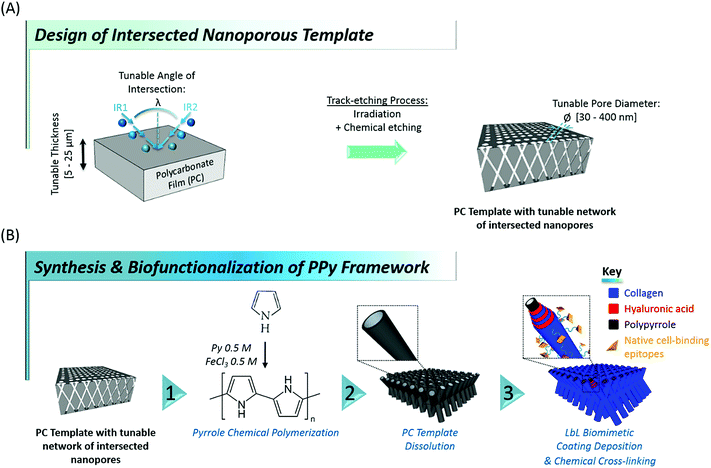
Designing tissue engineering and regenerative medicine strategies remains challenging in modern nanosciences, their successful outcome being largely dependent on the availability of suitable biointerfaces able to artificially recreate down to the nanoscale the conditions ultimately guiding cell fate in vivo.1–4 As the complex interplay of topographical, mechanical, biochemical and physicochemical stimuli controlling cell behaviour5–10 is originally provided in nature through the extracellular matrix (ECM), current trends in tissue engineering mainly focus on the development of biomaterials mimicking the native ECM.11–13 The complexity of the highly diverse cell-instructive cues found in vivo is reflected in the wide variety of bioinspired materials found in the literature, which attempt at replicating the 3-dimensional (3D) intricate network of fibrillary proteins, proteoglycans and glycoaminoglycans originally constituting the cell environment.14,15 In particular, in view of the variety of roles played by collagen in different tissues, research has focused on developing novel collagen-based biomaterials to mimic the architecture of native collagen-based ECM. Among the different methods reported up to now for producing fibers of dimensions close to those of native ECM (diameters ranging between 50 and 500 nm), electrospinning appears as an attractive and widely used method.16,17 This technique indeed allows to generate porous mats made of various synthetic and natural polymer fibers. However, due to the need of rather high electric fields and harsh solvents, electrospinning of collagen is still quite challenging when preservation of protein function is required.18 Another approach consists in combining ECM-derived biomacromolecules for the design of biomimetic multilayers,19–21 but their weak mechanical properties restrict their application to coatings of pre-existing biomaterials, as their in vivo transposition requires a supporting substrate. In an attempt to overcome the lack of mechanical integrity of biopolymers, different groups developed composite materials of collagen and multi-walled carbon nanotubes.22,23 Even though these composites showed and appropriate macroporous architecture and were effective at enhancing cell proliferation, no clear control could be exerted over the nanoscale topography, which is a widely recognized cell-instructive agent.24,25 These examples illustrate the complexity in meeting the requirements for a mechanically-stable architecture, easy to handle at the macroscale, while at the same time featuring the wide diversity of cell-regulating nanoscale tags found in native ECM.Here, we report on an original contribution to this current challenge. Hybrid mechanically-stable and self-supported polymer networks made of core–shell nanotubes, combining the biocompatibility and bioactivity of naturally-derived biomacromolecules with the mechanical stability of a rigid polymer core were designed and synthesized through a versatile template-based fabrication method (Fig. 1). For that purpose, flexible nanoporous membranes featuring a peculiar network of intersected nanopores26,27 were prepared through sequential polycarbonate (PC) film irradiation with heavy energetic ions at different incident angles, followed by chemical etching of the ion tracks created within the polymer film (see Fig. 1A). These membranes exhibit tunable properties such as membrane thickness (ranging from 5 to 25 μm), pore density (107 to 1010 pores per cm2), average pore diameter (ranging from 30 to 400 nm) and angle of intersection between crossing ion tracks (random or set at a fixed value). Next, polypyrrole (PPy), a stiff,28 electroactive and biocompatible29–32 polymer was synthesized within the pores of these PC membranes, used as templates, through a fast and easy chemical polymerization route33 (Fig. 1B, step 1). After removal of the PC template, arrays of intersected PPy nanotubes (Fig. 1B, step 2) with well-controlled architecture were obtained. A range of properties of the PC template were optimized to get freestanding nanofibrous interfaces. In a third step, engineered stiff PPy networks were functionalized with a self-assembled multilayer based on the alternate adsorption of two ECM-derived biopolymers: hyaluronic acid (HA) and type I collagen (Col) (Fig. 1B, step 3). Col is the most abundant protein in mammals and is ubiquitously present as a structural protein in the ECM.34,35 Type I Col, in particular, is well-known for featuring peptide sequences (i.e. GFOGER13,36 and DGEA37,38 motifs, etc.) responsible for triggering integrin-mediated cell adhesion39,40 and was also demonstrated to play a role in cellular differentiation, especially towards the osteoblastic lineage.37,41 In order to benefit from these bioactive properties, Col was thus specifically chosen to decorate the outermost layer of the biofunctionalized interfaces. HA, a linear glycosaminoglycan copolymer of D-glucuronic acid and N-acetyl-D-glucosamide also abundantly present in native ECM42 was more recently discovered to be granted with numerous biological functions. HA is indeed involved in cell signalling, including proliferation,43 migration44 and adhesion.45,46 HA was therefore selected as second partner for the layer-by-layer (LbL) assembly of the biomimetic multilayer, in combination with Col. Although the great interest of these two biomolecules has been clearly demonstrated, reports focusing on the LbL assembly of Col and HA remain scarce in the literature,47–50 probably due to the complexity of the selection of adequate assembling conditions. The evolution of the electrophoretic mobility (EPM) of the two biomacromolecules as a function of pH was therefore monitored to determine the isoelectric point (iep) of each biopolymer. The pH of the construction medium was fixed accordingly to trigger the LbL self-assembly of HA and Col, which was monitored by quartz crystal microbalance (QCM-D). After the LbL build-up was confirmed, the construction of the biomimetic (HA/Col) multilayer was initiated on the rigid PPy nanotubes network to yield a core–shell structure. The osteogenic properties of Col in combination with the hybrid core–shell structure of the engineered biointerfaces encouraged us to evaluate their potential as bone matrix mimics.51 The cytocompatibility of these new nanostructured biointerfaces was thus assessed through preliminary cell adhesion tests with murine MC3T3-E1 pre-osteoblasts, chosen as typical model cells whose behaviour (adhesion, proliferation, differentiation) highly depends on bone matrix organization.
Results and discussion
Template synthesis of self-supported PPy frameworks
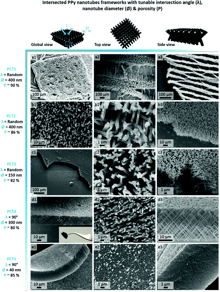
In order to select the set of template characteristics most likely to yield mechanically-stable, self-supported frameworks of intersected PPy nanotubes, chemical polymerization of Py was performed inside the pores of various PC membranes (PCT1-5, see Table 1). To evaluate the morphology and mechanical integrity of the resulting PPy nanostructures, they were collected through selective dissolution of the PC template and image by SEM. Pictures from Fig. 2 clearly demonstrate that architectures made of intersected PPy nanotubes were produced in all cases, with dimensions matching those of the used PC template. The first framework (Fig. 2a), issued from template PCT1 with an average pore diameter of 400 nm and random angles of intersection between nanotubes, shows a microporous architecture (Fig. 2a1), as could be expected with a porosity as high as 90%. When zooming in (Fig. 2a2), we can clearly distinguish widely spaced yet interconnected sheets of nanotubes, responsible for microporous lamellar structure of the whole interface. When observing the framework sideways (Fig. 2a3), the lamellar structure originating from these interconnected nanotube sheets is even more blatant. Although such an interface combining a microporous structure and nanotopographical cues could turn out to be particularly interesting to study and control cell behaviour, it does not fulfil the requirement for a self-supported architecture. The lack of mechanical stability is clearly a consequence of the too high porosity of the intersecting network, which is in turn the result of a too low pore density of the original templating PC membrane. When designing template PCT2, the density of nanopores was therefore increased while the average pore diameter was left unchanged. The resulting second network is slightly less porous than the first one: a highly homogeneous interface is obtained, both at the micro- and macroscale (Fig. 2b1). At higher magnification (Fig. 2b2), some intersections between nanotubes are clearly visible. However, images of the edge of the nanostructured framework (Fig. 2b3) reveal that the network is partially collapsing. The still high porosity (∼86%) is again responsible for the low mechanical strength of the structure. So as to impart better mechanical stability, the overall porosity was further decreased while the number of intersections between nanotubes was increased. For that purpose, a third PC template was designed with a lower pore diameter (∅ = 150 nm) coupled to a higher pore density (template PCT3 of Table 1). A highly homogeneous framework, both at the macro- and microscale, resulted again from the polymerization of Py within this template (Fig. 2c1 and c2). Nonetheless, the sides of the PPy network were unstable (Fig. 2c3), as nanotubes were still collapsing. Further detailed observations evidenced that this instability can be attributed to a too low density of nanotube intersections, which is a side effect of the reduction of the average nanotube diameter. To conciliate these two conflicting requirements, a new parameter was adjusted, i.e. the angle at which nanotubes intersect (λ). A new PC template (template PCT4 of Table 1) was therefore designed to combine a level of porosity set at 80% with an intermediate pore diameter of 300 nm. The angle of intersection between tubes was set at 90°. This implies the PC film to be irradiated twice with an ion beam aligned at +45° and −45° with respect to the normal of the template surface. The resulting PPy framework shows a highly uniform and well-organized architecture, with PPy nanotubes intersecting at an angle of 90° (Fig. 2d1–d3). Furthermore, the intersected PPy network meets the requirements for a self-supported material (see inset in Fig. 2d1) and is therefore optimal to pursue the targeted applications. Further exploiting the set of refined parameters (i.e., intersecting angle λ = 90°, average porosity ∼ 80–85%), freestanding PPy networks composed of nanotubes with a diameter as low as 40 nm were successfully synthesized (Fig. 2e1–e3), strongly evidencing the possibility to finely tune the nanotopography presented by the nanostructured PPy platforms.
| PC template | Pore diameter: ∅ (nm) | Pore density: ρ (#pores per cm2) | Template thickness: L (μm) | Angle of intersection: λ (°) | Computed porosity of resulting framework: P (%) |
|---|---|---|---|---|---|
| PCT1 | 400 | 6.4 × 10⁷ | 25 | Random (0 ≤ λ ≤ 90) | ∼90 |
| PCT2 | 400 | 1.05 × 10⁸ | 25 | Random (0 ≤ λ ≤ 90) | ∼86 |
| PCT3 | 150 | 1 × 10⁹ | 25 | Random (0 ≤ λ ≤ 90) | ∼82 |
| PCT4 | 300 | 2.8 × 10⁸ | 25 | ∼90 | ∼80 |
| PCT5 | 40 | 1.2 × 10¹⁰ | 25 | ∼90 | ∼85 |
Selection of favourable conditions for the biomimetic (Col/HA) self-assembly
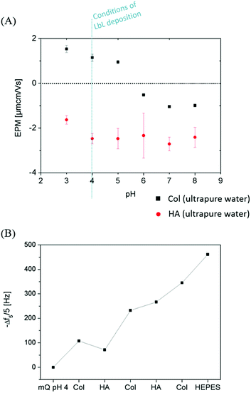
Monitoring the electrophoretic mobility of the two biopolymers as a function of pH allowed the determination of their experimental isoelectric point (iep). As shown in Fig. 3A, the iep of type I Col was found to be ∼5.5, while the one of HA was determined to be below 3. Both values were in good agreement with the ones usually reported in the literature52,53 The electrostatic interactions existing between the two partners in mildly acidic conditions (pH ∼ 4) can thus be exploited to build LbL assemblies, using Col as a polycation and HA as a polyanion, as previously scarcely outlined in the literature.47–50 To further confirm the adequacy of the chosen conditions, the build-up of the (Col/HA) multilayer was monitored in situ, on reference substrates, using QCM-D (Fig. S1†). The change of Δf recorded upon adsorption at the crystal surface is directly proportional to the mass of adsorbed molecules; a relation typically embodied by the Sauerbrey's equation, which holds for homogeneous and rigid thin films: . Correspondingly, Fig. 3B displays, after extraction of the −Δf recorded in Fig. S1,† the gradual evolution of the mass adsorbed at the crystal surface following the stepwise adsorption of HA and Col. The relatively linear increase in Δf upon injection of each biopolymer, demonstrates the capacity of these molecules to interact together, in order to create complex multilayered architecture in a LbL fashion. The high dissipation increase recorded after each Col injection step is characteristic of the adsorption of Col as a soft and viscoelastic layer, as previously described by Landoulsi et al.54
Circulation of HEPES buffer (10 mM, NaCl 0.15 M, pH 7.4) on the self-assembled (Col/HA) multilayer leads to a swelling of the biopolymer multilayer, without causing any subsequent multilayer deconstruction. The (Col/HA) multilayer built in the chosen conditions is thus stable under physiological conditions, in contrast to the previous conclusions of Johansson et al.48
Biofunctionalization of PPy frameworks
In order to produce ECM-like biointerfaces, the alternate adsorption of HA and Col was initiated on the optimally designed self-supported PPy frameworks derived from template PCT4. SEM images showing the PPy interface sideways, before (Fig. 4a–c) and after (Fig. 4d–f) LbL assembly of 6 bilayers of the (HA/Col) system, clearly highlight the effective construction of a biopolymer shell surrounding the nanotubes (Fig. 4d–f). Furthermore, Fig. 4c and f confirms the tubular nature of the framework building blocks, as central open pores can be distinguished. Aerial views of the scaffolding PPy platforms further emphasize the presence of the polymer coating (Fig. S2c and d†). The growth of the biomimetic (HA/Col) multilayer was further investigated by SEM, as the rigid PPy network was submitted to the deposition of an increasing number of (HA/Col) bilayers (starting from 3 up to 12 bilayers) (Fig. 5-sideways and S3-aerial views). While the growth of the (HA/Col)n system appears to be first limited, in the early stages of the deposition process, to a soft polymer adlayer directly covering the nanotubes surface (Fig. 5a and b), it rapidly expands towards the intertubular space, finally merging after deposition of 12 bilayers into a dense polymer gel completely masking the constituting tubules (Fig. 5d-sideways and Fig. S3d†-aerial view). The fibrillary structure of the polymer crust can be attributed to the fibrillation of Col, a phenomenon commonly reported under the studied conditions.49,55 The progressive growth of the HA/Col multilayer further opens the opportunity to tune the thickness of the biomimetic shell functionalizing the rigid PPy interface.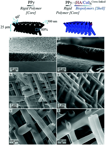 | ||
| Fig. 4 SEM images showing a side view of PPy framework (a–c) before biofunctionalization [increasing magnification from a to c] and (d–f) after LbL deposition of 6 bilayers of HA & Col. | ||
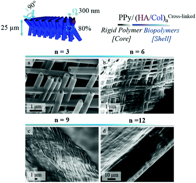 | ||
| Fig. 5 SEM images showing a side view of PPy frameworks after deposition of an increasing number of (HA/Col) bilayers: (a) 3 bilayers, (b) 6 bilayers, (c) 9 bilayers and (d) 12 bilayers. | ||
Information regarding the surface chemistry of (un)coated PPy biointerfaces was obtained using Fourier-transform infrared spectroscopy with an attenuated total reflection system (ATR-FTIR). FTIR spectra of uncoated and (HA/Col)6-biofunctionalized PPy frameworks are compared in Fig. 6 (A & B, respectively). The unfunctionalized PPy interface displays the typical fingerprint of naked PPy, with characteristic absorbance peaks like the band centered around 1550 cm−1 representing the Py ring vibration, the C–N stretching vibration peak at ∼1470 cm−1, the C–H vibration band at ∼1040 cm−1 and the absorbance peak at ∼1320 cm−1 attributed to the C–C stretching vibration.56,57 The change in interfacial chemistry upon introduction of the biomimetic (HA/Col)6 multilayer is clearly visible in the FTIR spectrum and confirms the successful biofunctionalization of the PPy network. Indeed, while the peaks characteristic of PPy disappear, a set of absorbance bands highly characteristic of proteins and polysaccharides can be identified:58,59 the amide I, II and III bands centered at ∼1650 cm−1, ∼1550 cm−1 and ∼1320 cm−1, respectively; the absorbance peak located around 1150 cm−1, attributed to the antisymmetric C–O–C stretching of glycosidic groups present in carbohydrate moieties; the vibration band of carboxylate groups at ∼1410 cm−1; as well as the broad and intense band located at ∼3250 cm−1 which corresponds to N–H and O–H groups engaged in hydrogen bonds in both HA and Col.
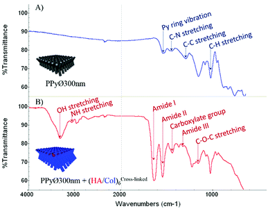 | ||
| Fig. 6 ATR-FTIR spectra of (A) uncoated and (B) (HA/Col)6-coated PPy framework (PPy framework obtained from PCT4). | ||
Preliminary study of cell adhesion & proliferation
Murine MC3T3-E1 pre-osteoblasts, widely used as model cell line for bone tissue engineering applications,60,61 were selected to evaluate in vitro the potential of (un)modified PPy frameworks as cell-instructive biointerfaces. The number of (HA/Col) bilayers decorating the PPy core was set at 6 for all cellular tests, to avoid masking the underlying nanotopography. When seeded at a density of 60![[thin space (1/6-em)]](https://www.rsc.org/images/entities/char_2009.gif) 000 cells per mL and after 24 h of culture, cells were found to adhere to both uncoated and (HA/Col)6-biofunctionalized nanostructured PPy frameworks (Fig. S4C & D†). Given the specificities of the engineered biointerfaces (opaque black colour, high developed specific surface area, non-uniformly smooth surface, etc.), cell densities were difficult to assess based solely on microscopic analyses. Cells seeded on the PPy networks were indeed found to interact both with the tips of the constituting nanotubes as well as with their cylindrical body, as cells were adhering to the vertical edges of the biointerfaces (Fig. 8C2 and 7B3). In contrast, a 2D surface only was explored by cells on glass. Total DNA quantification was therefore selected as an objective parameter for the comparison of samples (Fig. 9).
000 cells per mL and after 24 h of culture, cells were found to adhere to both uncoated and (HA/Col)6-biofunctionalized nanostructured PPy frameworks (Fig. S4C & D†). Given the specificities of the engineered biointerfaces (opaque black colour, high developed specific surface area, non-uniformly smooth surface, etc.), cell densities were difficult to assess based solely on microscopic analyses. Cells seeded on the PPy networks were indeed found to interact both with the tips of the constituting nanotubes as well as with their cylindrical body, as cells were adhering to the vertical edges of the biointerfaces (Fig. 8C2 and 7B3). In contrast, a 2D surface only was explored by cells on glass. Total DNA quantification was therefore selected as an objective parameter for the comparison of samples (Fig. 9).
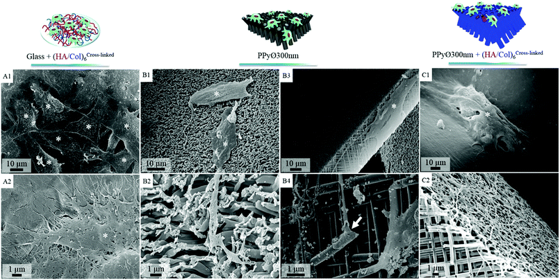 | ||
Fig. 7 SEM images of cell-seeded biointerfaces after 6 days of in vitro culture (seeding density 60![[thin space (1/6-em)]](https://www.rsc.org/images/entities/char_2009.gif) 000 cells per mL): cells (asterisk) adhering on uncoated glass slide (positive control, Fig. S5†), (A1 and 2) (HA/Col)6-coated glass slide, (B1–4) uncoated PPy framework ∅ 300 nm (cytoplasmic elongations are shown to interact with nanotubes [arrows]), (C1 and 2) (HA/Col)6-coated PPy framework ∅ 300 nm. 000 cells per mL): cells (asterisk) adhering on uncoated glass slide (positive control, Fig. S5†), (A1 and 2) (HA/Col)6-coated glass slide, (B1–4) uncoated PPy framework ∅ 300 nm (cytoplasmic elongations are shown to interact with nanotubes [arrows]), (C1 and 2) (HA/Col)6-coated PPy framework ∅ 300 nm. | ||
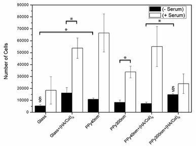 | ||
| Fig. 9 MC3T3-E1 proliferation after 24 hours of culture in the presence or absence of 10% foetal bovine serum supplementation. Bars are means ± SEM of triplicates. *p < 0.05, §p < 0.01. | ||
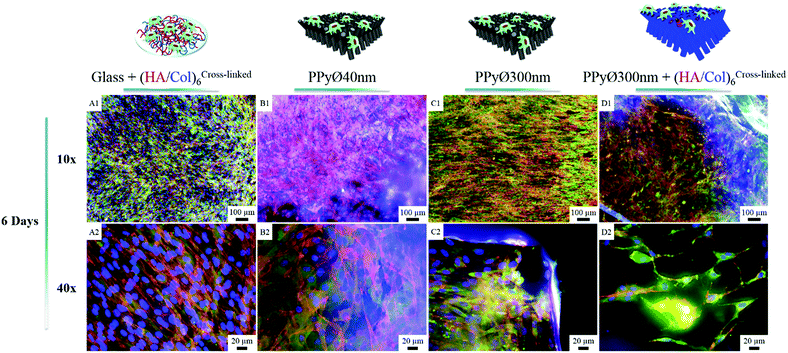
In absence of serum, the produced biointerfaces were shown to promote cell adhesion to an extent similar to or higher than uncoated glass, which is known for its cytophilic properties.62 In particular, networks of bare nanotubes with a diameter of 40 nm and biofunctionalized nanotubes of 300 nm were found to host significantly more cells than glass. In addition to demonstrating the cytocompatibility of the engineered biointerfaces, these results emphasize the ability of the biomimetic (HA/Col) coating to be an efficient substitute for the undefined mixture of proteins found in serum while ensuring a similar cell adhesion level. Serum-supplemented cultures did not show any significant differences in cell adhesion and proliferation depending on sample type, all the samples eliciting a cell adhesiveness as high as the one of glass. After 6 days of culture, cells had proliferated on all substrates and were well-spread (Fig. 8). The morphology of the seeded cells was found to be influenced by their supporting substrate. They adopted a polygonal shape, characteristic of the MC3T3-E1 cells,50,63 when cultured on uncoated glass slides (Fig. S4(A2 and A4†)), while they were found to adopt a more stellate shape both on (HA/Col)6-coated glass slides and (un)coated PPy frameworks (Fig. S4(B2, B4, C2 and C4†). In particular, cells formed many pseudopods in presence of the biomimetic (HA/Col)6 coating (Fig. S4(B1, B4, D1 and D4†), which might be due to the specific anchorage of cells to the integrin-binding cues located on collagen molecules, non-uniformly distributed on the substrate.64 On nanostructured interfaces, the formation of filopodia might be increased as adherent cells have to contact multiple nanotubular heads to anchor themselves on the surface. The heterogeneous distribution of cell-adhesive cues and nanotopography might be both at play in dictating the morphology of cells adhering to (HA/Col)6-functionalized nanobiointerfaces. Further investigations will be carried out to define whether such morphological changes can be correlated with a modification of the cell differentiation ability. SEM analyses (Fig. 7) further highlight the presence of numerous cell protrusions, which wrap themselves around the tubules (Fig. 7B2 & B4). This observation opens perspectives for the use of the hollow cavity of the tubes, which is directly in contact with the cytoplasmic projections, to deliver bioactive agents. A dense fibrillary network is found on biofunctionalized systems, fully covering the samples (Fig. 7C2). It is attributed to a reorganization of the (HA/Col)6 multilayer upon dehydration rather than to a de novo synthesis of ECM macromolecules by the adherent cells (as demonstrated in Fig. S6†). When increasing the seeded cell density to 1![[thin space (1/6-em)]](https://www.rsc.org/images/entities/char_2009.gif) 000
000![[thin space (1/6-em)]](https://www.rsc.org/images/entities/char_2009.gif) 000 cells per mL, pre-osteoblast cells were found to fully colonize the surface of all (un)coated PPy interfaces after 6 days in culture, illustrating the cytocompatibility of the produced biointerfaces (Fig. 8B–D). Further experiments will be carried out to specifically determine the effect of a variation of the tubes diameter on cell adhesion and proliferation as well as to evaluate the influence of the produced biointerfaces on cell differentiation.
000 cells per mL, pre-osteoblast cells were found to fully colonize the surface of all (un)coated PPy interfaces after 6 days in culture, illustrating the cytocompatibility of the produced biointerfaces (Fig. 8B–D). Further experiments will be carried out to specifically determine the effect of a variation of the tubes diameter on cell adhesion and proliferation as well as to evaluate the influence of the produced biointerfaces on cell differentiation.
Conclusion
Biofunctional rigid nanostructured PPy frameworks with highly tunable features were reproducibly fabricated using the simple and cost-effective hard-templating process combined with the versatile LbL technique. In particular, mechanically-stable frameworks made of intersected PPy nanotubes with a diameter of 40 or 300 nm and an angle of 90° between crossing tubes were successfully synthesized. These self-supported PPy architectures were further functionalized with a biomimetic coating, therefore combining two often antagonistic factors: mechanical stability and bioactivity. Such hybrid systems were shown to elicit good cell adhesion and cytocompatibility. Murine MC3T3-E1 pre-osteoblast cells were indeed able to adhere and proliferate on both uncoated and (HA/Col)6-functionalized PPy nanostructures, reaching confluence after 6 days. These synthesized hybrid nanostructures hold many advantages, including: highly tunable geometry, nanotopography (values ranging from 30 to 400 nm were selected in this work, but the range of achievable nanotube diameters can be considerably extended), interconnected porosity and potentially electrical conductivity (which could be modulated by varying the tubular diameter33), together with biocompatibility and high versatility of the LbL-deposited functional coating (HA and Col, ECM-derived biopolymers, were selected in the present work for the LbL process, but many other polyelectrolyte combinations could be used). Such biointerfaces could provide further cell-signalling cues through the incorporation of bioactive molecules either inside the tubular polypyrrole core or directly within the biomimetic shell. We thus foresee that his new type of nanobiointerfaces could be useful as cell-instructive materials. Relying on the promising preliminary cellular tests, carried out with pre-osteoblastic cells which demonstrated the cytophilicity of both coated and uncoated frameworks, future prospects will consider the extension of the study to stem cells. An interesting area of research indeed opens up to determine whether their differentiation could be oriented towards a wide range of tissues by appropriately tailoring the set of cues presented by the bioengineered interfaces, which could be used as a coating on biomaterials or as membranes making the bridge between different tissues. Finally, these frameworks made of intersected nanotubes, developing a high specific surface area and that can be functionalized at will, pave the way towards the elaboration of multifunctional platforms useful for a broad range of applications in the field of drug delivery, biosensing or nanocatalysis.Experimental section
Preparation of nanostructured frameworks of intersected PPy nanotubes
Biofunctionalization of PPy structures
![[thin space (1/6-em)]](https://www.rsc.org/images/entities/char_2009.gif) :
:![[thin space (1/6-em)]](https://www.rsc.org/images/entities/char_2009.gif) 2 v/v] for 20 min, before being thoroughly rinsed with ultrapure water and dried under nitrogen flow. All measurements were performed in a Q-Sense E4 system [Gothenburg, Sweden] following the same protocol: resonance frequencies of the crystals were obtained under buffer for the different overtones, and the shifts of frequency (Δf) and of dissipation (ΔD) were both monitored as a function of time upon stepwise injection of each of the two biopolymers.
2 v/v] for 20 min, before being thoroughly rinsed with ultrapure water and dried under nitrogen flow. All measurements were performed in a Q-Sense E4 system [Gothenburg, Sweden] following the same protocol: resonance frequencies of the crystals were obtained under buffer for the different overtones, and the shifts of frequency (Δf) and of dissipation (ΔD) were both monitored as a function of time upon stepwise injection of each of the two biopolymers.The flow was set at 30 μL min−1 using a peristaltic pump while the temperature was fixed at 25 °C. The solutions of either Col or HA molecules were alternately injected in the system and allowed to adsorb on the crystals during 1 h. Each adsorption step was then followed by a rinsing step, conducted in the corresponding pH-adjusted solution for at least 30 min. Dissipation and frequency shifts recorded for the 5th overtone are displayed in this paper.
Fourier transform infrared analysis
The in situ Fourier transform infrared (FTIR) spectroscopy in attenuated total reflection (ATR) mode experiments were performed with a Nexus 870 FT-IR spectrometer (Nicolet, USA) coupled to a Continuum microscope (Thermo Spectra-Tech, USA). Unmodified and biofunctionalized PPy frameworks were deposited on a Si crystal and ATR-FTIR spectra, averaged over 128 scans, were recorded in the range of 400–4000 cm−1 with 8 cm−1 resolution. The spectra were analysed using the software OMNIC.Preliminary cell adhesion and proliferation tests
![[thin space (1/6-em)]](https://www.rsc.org/images/entities/char_2009.gif) 000 U mL−1 penicillin & 10
000 U mL−1 penicillin & 10![[thin space (1/6-em)]](https://www.rsc.org/images/entities/char_2009.gif) 000 μg mL−1 streptomycin, Gibco®) at 37 °C with 5% CO2. The supplemented culture medium was renewed every 3 days and confluent cells were subcultured through trypsinization (trypsin EDTA, Lonza) until reaching passage 23, where the cells were seeded either on nanostructured PPy frameworks (uncoated or (HA/Col)6-coated) or control substrates (virgin or (HA/Col)6-coated circular glass slides, ∅ 10 mm, Thermo Scientific). All samples were sterilized with 70% ethanol for 30 min followed by 4 times rinsing with sterile PBS prior to cell seeding. The samples were kept in a 24-well plate (Costar® Ultra-low attachment 24 well plate from Corning), and 60
000 μg mL−1 streptomycin, Gibco®) at 37 °C with 5% CO2. The supplemented culture medium was renewed every 3 days and confluent cells were subcultured through trypsinization (trypsin EDTA, Lonza) until reaching passage 23, where the cells were seeded either on nanostructured PPy frameworks (uncoated or (HA/Col)6-coated) or control substrates (virgin or (HA/Col)6-coated circular glass slides, ∅ 10 mm, Thermo Scientific). All samples were sterilized with 70% ethanol for 30 min followed by 4 times rinsing with sterile PBS prior to cell seeding. The samples were kept in a 24-well plate (Costar® Ultra-low attachment 24 well plate from Corning), and 60![[thin space (1/6-em)]](https://www.rsc.org/images/entities/char_2009.gif) 000; 500
000; 500![[thin space (1/6-em)]](https://www.rsc.org/images/entities/char_2009.gif) 000 or 1
000 or 1![[thin space (1/6-em)]](https://www.rsc.org/images/entities/char_2009.gif) 000
000![[thin space (1/6-em)]](https://www.rsc.org/images/entities/char_2009.gif) 000 cells were seeded per well (volume of solution per well = 1 mL).
000 cells were seeded per well (volume of solution per well = 1 mL).![[thin space (1/6-em)]](https://www.rsc.org/images/entities/char_2009.gif) :
:![[thin space (1/6-em)]](https://www.rsc.org/images/entities/char_2009.gif) 175 in blocking buffer) (FAK100, Millipore) during 1 h at room temperature. Cells were then washed 3 times and reacted with (FITC)-conjugated secondary antibody (1
175 in blocking buffer) (FAK100, Millipore) during 1 h at room temperature. Cells were then washed 3 times and reacted with (FITC)-conjugated secondary antibody (1![[thin space (1/6-em)]](https://www.rsc.org/images/entities/char_2009.gif) :
:![[thin space (1/6-em)]](https://www.rsc.org/images/entities/char_2009.gif) 150 in PBS) (AP124F, FITC-conjugated goat anti-mouse IgG, Millipore) for 1 h at room temperature. To detect actin filaments simultaneously, (TRITC)-conjugated phalloidin (1
150 in PBS) (AP124F, FITC-conjugated goat anti-mouse IgG, Millipore) for 1 h at room temperature. To detect actin filaments simultaneously, (TRITC)-conjugated phalloidin (1![[thin space (1/6-em)]](https://www.rsc.org/images/entities/char_2009.gif) :
:![[thin space (1/6-em)]](https://www.rsc.org/images/entities/char_2009.gif) 100 in PBS) (FAK100, Millipore) was added in the secondary antibody solution. Finally, the substrates were washed 3 times before being mounted in Vectashield containing DAPI (Vector Laboratories, Peterborough, UK) to stain the nuclei. Immunolabeled cells were observed using an epifluorescence microscope (Olympus, IX71). In order to further analyse the cell–material interactions by SEM, cell-seeded samples were washed three times with PBS, gradually dehydrated in 20, 40, 60, 80 and 100% ethanol for 5 min each, covered with hexamethyldisilazane and left to dry overnight in a fumehood. The samples were finally sputter-coated with 10 nm gold prior to imaging.
100 in PBS) (FAK100, Millipore) was added in the secondary antibody solution. Finally, the substrates were washed 3 times before being mounted in Vectashield containing DAPI (Vector Laboratories, Peterborough, UK) to stain the nuclei. Immunolabeled cells were observed using an epifluorescence microscope (Olympus, IX71). In order to further analyse the cell–material interactions by SEM, cell-seeded samples were washed three times with PBS, gradually dehydrated in 20, 40, 60, 80 and 100% ethanol for 5 min each, covered with hexamethyldisilazane and left to dry overnight in a fumehood. The samples were finally sputter-coated with 10 nm gold prior to imaging.![[thin space (1/6-em)]](https://www.rsc.org/images/entities/char_2009.gif) 000 cells per well) with or without 10% FBS (Lonza), was quantified using a CyQUANT® Proliferation Assay kit (Molecular Probes, USA). After 24 h of culture, adherent cells were rinsed twice with sterile PBS before being detached from their corresponding substrate using trypsin and collected in a cryotube. Cell suspensions were then centrifuged at 1500 RPM for 5 min at 4 °C to recover cell pellets. After being washed with sterile PBS to remove all traces of phenol red (which might interfere with the CyQUANT® kit) and subsequently centrifuged, cells pellets were frozen at −80 °C. Before the start of the assay, the concentrated cell lysis buffer (CLB) provided with the CyQUANT® kit was diluted 20 times in ultrapure water. A reagent solution was then freshly prepared by diluting 80 times the CyQUANT® DNA-labelling GR dye with the prepared CLB solution, and kept protected from light. Cell pellets were thawed and resuspended in 200 μL of the CLB/GR dye solution. The obtained cell suspensions were independently transferred to a 96-well microplate. One well containing only the CLB/GR dye solution (i.e., with no cell) was used as blank. The fluorescence intensity of each well was then measured with a Tecan Infinite M200-PRO microplate reader with an excitation and emission wavelength set at 480 nm and 520 nm, respectively. In order to build a calibration curve displaying the fluorescence intensity as a function of the cell number, reference pellets containing 500
000 cells per well) with or without 10% FBS (Lonza), was quantified using a CyQUANT® Proliferation Assay kit (Molecular Probes, USA). After 24 h of culture, adherent cells were rinsed twice with sterile PBS before being detached from their corresponding substrate using trypsin and collected in a cryotube. Cell suspensions were then centrifuged at 1500 RPM for 5 min at 4 °C to recover cell pellets. After being washed with sterile PBS to remove all traces of phenol red (which might interfere with the CyQUANT® kit) and subsequently centrifuged, cells pellets were frozen at −80 °C. Before the start of the assay, the concentrated cell lysis buffer (CLB) provided with the CyQUANT® kit was diluted 20 times in ultrapure water. A reagent solution was then freshly prepared by diluting 80 times the CyQUANT® DNA-labelling GR dye with the prepared CLB solution, and kept protected from light. Cell pellets were thawed and resuspended in 200 μL of the CLB/GR dye solution. The obtained cell suspensions were independently transferred to a 96-well microplate. One well containing only the CLB/GR dye solution (i.e., with no cell) was used as blank. The fluorescence intensity of each well was then measured with a Tecan Infinite M200-PRO microplate reader with an excitation and emission wavelength set at 480 nm and 520 nm, respectively. In order to build a calibration curve displaying the fluorescence intensity as a function of the cell number, reference pellets containing 500![[thin space (1/6-em)]](https://www.rsc.org/images/entities/char_2009.gif) 000 MC3T3-E1 cells were resuspended in CLB and serially diluted (by a factor 2) in the wells of a 96-well microplate, so as to span cell numbers from 244 to 250
000 MC3T3-E1 cells were resuspended in CLB and serially diluted (by a factor 2) in the wells of a 96-well microplate, so as to span cell numbers from 244 to 250![[thin space (1/6-em)]](https://www.rsc.org/images/entities/char_2009.gif) 000 cells. CLB/GR dye solution was then added to each well to reach a final volume of 200 μL, whose fluorescence intensity was measured. Three repetitions of the calibration curve were achieved per sample group (i.e., with or without addition of FBS). For each repetition, a well containing only the CLB/GR dye solution (i.e., with no cells) was used as blank.
000 cells. CLB/GR dye solution was then added to each well to reach a final volume of 200 μL, whose fluorescence intensity was measured. Three repetitions of the calibration curve were achieved per sample group (i.e., with or without addition of FBS). For each repetition, a well containing only the CLB/GR dye solution (i.e., with no cells) was used as blank.Conflicts of interest
There are no conflicts to declare.Acknowledgements
The authors thank the it4ip company for designing and providing polycarbonate and PET membranes; Prof. Bernard Knoops for granting the access to the cell culture facilities, Sarah Becker for her help with cell culture experiments; Dr Jessem Landoulsi and Elodie Colaco for EPM data; Sabine Bebelman for her support on ATR-FTIR measurements. The work was supported by the Belgian Science Policy (IAP/PAI P7/05), the Wallonia/Brussels Community (ARC 13/18-052) and the Belgian Funds for Scientific Research F.R.S.-FNRS.Notes and references
- S. Shah, A. Solanki and K. B. Lee, Acc. Chem. Res., 2016, 49, 17–26 CrossRef PubMed.
- M. J. Dalby, N. Gadegaard and R. O. C. Oreffo, Nat. Mater., 2014, 13, 558–569 CrossRef PubMed.
- M. D. Mager, V. LaPointe and M. M. Stevens, Nat. Chem., 2011, 3, 582–589 CrossRef PubMed.
- X. Liu and S. Wang, Chem. Soc. Rev., 2014, 43, 2385–2401 RSC.
- C. S. Chen, M. Mrksich, S. Huang, G. M. Whitesides and D. E. Ingber, Science, 1997, 276, 1425–1428 CrossRef PubMed.
- X. Yao, R. Peng and J. Ding, Adv. Mater., 2013, 25, 5257–5286 CrossRef PubMed.
- A. J. Engler, S. Sen, H. L. Sweeney and D. E. Discher, 2006, 677–689.
- J. Fu, Y. Wang, M. T. Yang, R. A. Desai, X. Yu, Z. Liu and C. S. Chen, Nat. Methods, 2010, 7, 733–736 CrossRef PubMed.
- J. H. Wen, L. G. Vincent, A. Fuhrmann, Y. S. Choi, K. C. Hribar, H. Taylor-weiner, S. Chen and A. J. Engler, Nat. Mater., 2014, 13, 979–987 CrossRef PubMed.
- C. Yang, M. W. Tibbitt, L. Basta and K. S. Anseth, Nat. Mater., 2014, 13, 645–652 CrossRef PubMed.
- P. X. Ma, Adv. Drug Delivery Rev., 2008, 60, 184–198 CrossRef PubMed.
- N. Gjorevski, N. Sachs, A. Manfrin, S. Giger, M. E. Bragina, P. Ordonnez-Moran, H. Clevers and M. P. Lutolf, Nature, 2016, 539, 560–564 CrossRef PubMed.
- K. Von Der Mark, J. Park, S. Bauer and P. Schmuki, Cell Tissue Res., 2010, 339, 131–153 CrossRef PubMed.
- H. Fernandes, L. Moroni, C. van Blitterswijk and J. de Boer, J. Mater. Chem., 2009, 19, 5474 RSC.
- C. Frantz, K. M. Stewart and V. M. Weaver, J. Cell Sci., 2010, 123, 4195–4200 CrossRef PubMed.
- M. D. Schofer, U. Boudriot, C. Wack, I. Leifeld, C. Gräbedünkel, R. Dersch, M. Rudisile, J. H. Wendorff, A. Greiner, J. R. J. Paletta and S. Fuchs-Winkelmann, J. Mater. Sci.: Mater. Med., 2009, 20, 767–774 CrossRef PubMed.
- M. P. Prabhakaran, J. Venugopal and S. Ramakrishna, Acta Biomater., 2009, 5, 2884–2893 CrossRef PubMed.
- B. D. Walters and J. P. Stegemann, Acta Biomater., 2014, 10, 1488–1501 CrossRef PubMed.
- J. M. Silva, R. L. Reis and J. F. Mano, Small, 2016, 4308–4342 CrossRef PubMed.
- K. Ren, T. Crouzier, C. Roy and C. Picart, Adv. Funct. Mater., 2008, 18, 1378–1389 CrossRef PubMed.
- C. Picart, Curr. Med. Chem., 2008, 15, 685–697 CrossRef PubMed.
- E. E. da Silva, H. H. M. Della Colleta, A. S. Ferlauto, R. L. Moreira, R. R. Resende, S. Oliveira, G. T. Kitten, R. G. Lacerda and L. O. Ladeira, Nano Res., 2009, 2, 462–473 CrossRef.
- E. Hirata, M. Uo, H. Takita, T. Akasaka, F. Watari and A. Yokoyama, J. Biomed. Mater. Res., Part B, 2009, 90 B, 629–634 CrossRef PubMed.
- J. Park, S. Bauer, K. von der Mark and P. Schmuki, Nano Lett., 2007, 7, 1686–1691 CrossRef PubMed.
- E. Hirata, M. Uo, H. Takita, T. Akasaka, F. Watari and A. Yokoyama, Carbon, 2011, 49, 3284–3291 CrossRef.
- M. Rauber, I. Alber, S. Muöller, R. Neumann, O. Picht, C. Roth, A. Schoökel, M. E. Toimil-Molares and W. Ensinger, Nano Lett., 2011, 11, 2304–2310 CrossRef PubMed.
- L. Piraux, V. Antohe, E. Ferain and D. Lahem, RSC Adv., 2016, 6, 21808–21813 RSC.
- S. Cuenot, S. Demoustier-Champagne and B. Nysten, Phys. Rev. Lett., 2000, 85, 1690–1693 CrossRef PubMed.
- N. K. Guimard, N. Gomez and C. E. Schmidt, Prog. Polym. Sci., 2007, 32, 876–921 CrossRef.
- Y. Wei, X. Mo, P. Zhang, Y. Li, J. Liao, Y. Li, J. Zhang, C. Ning, S. Wang, X. Deng and L. Jiang, ACS Nano, 2017, 11, 5915–5924 CrossRef PubMed.
- X. Liu, Z. Yue, M. J. Higgins and G. G. Wallace, Biomaterials, 2011, 32, 7309–7317 CrossRef PubMed.
- J. Zeng, Z. Huang, G. Yin, J. Qin, X. Chen and J. Gu, Colloids Surf., B, 2013, 110, 450–457 CrossRef PubMed.
- J. Duchet, R. Legras and S. Demoustier-Champagne, Synth. Met., 1998, 113–122 CrossRef.
- M. J. Beckman, K. J. Shields and R. F. Diegelmann, Encycl. Biomater. Biomed. Eng., 2004, 324–334 Search PubMed.
- K. A. Piez, Encycl. Polym. Sci. Eng., 1985, 699–727 Search PubMed.
- J. Emsley, C. G. Knight, R. W. Farndale, M. J. Barnes and R. C. Liddington, Cell, 2000, 101, 47–56 CrossRef PubMed.
- M. Mizuno, R. Fujisawa and Y. Kuboki, J. Cell. Physiol., 2000, 184, 207–213 CrossRef PubMed.
- M. Mizuno and Y. Kuboki, J. Biochem., 2001, 129, 133–138 CrossRef PubMed.
- P. Nykvist, H. Tu, J. Ivaska, J. Ka and T. Pihlajaniemi, J. Biol. Chem., 2000, 275, 8255–8261 CrossRef PubMed.
- J. A. Schiro, B. M. C. Chan, W. T. Roswit, P. D. Kassner, A. P. Pentland, M. E. Hemler, A. Z. Eisen and T. S. Kupper, Cell, 1991, 67, 403–410 CrossRef PubMed.
- R. M. Salasznyk, W. A. Williams, A. Boskey, A. Batorsky and G. E. Plopper, J. Biomed. Biotechnol., 2004, 1, 24–34 CrossRef PubMed.
- T. C. Laurent, U. B. Laurent and J. R. Fraser, Immunol. Cell Biol., 1996, 74, A1–A7 CrossRef PubMed.
- M. Yoneda, S. Shimizu, Y. Nishi, M. Yamagata, S. Suzuki and K. Kimata, J. Cell Sci., 1988, 90(Pt 2), 275–286 Search PubMed.
- T. Nishida, M. Nakamura, M. Hiroshi and T. Otori, Exp. Eye Res., 1991, 53, 753–758 CrossRef PubMed.
- E. A. Turley, P. W. Noble and L. Y. W. Bourguignon, J. Biol. Chem., 2002, 277, 4589–4592 CrossRef PubMed.
- C. B. Underhill and B. P. Toole, J. Cell Biol., 1979, 82, 475–484 CrossRef PubMed.
- H. Ao, Y. Xie, H. Tan, S. Yang, K. Li, X. Wu, X. Zheng and T. Tang, J. R. Soc., Interface, 2013, 10, 20130070 CrossRef PubMed.
- J. Å. Johansson, T. Halthur, M. Herranen, L. Söderberg, U. Elofsson and J. Hilborn, Biomacromolecules, 2005, 6, 1353–1359 CrossRef PubMed.
- J. Zhang, B. Senger, D. Vautier, C. Picart, P. Schaaf, J. C. Voegel and P. Lavalle, Biomaterials, 2005, 26, 3353–3361 CrossRef PubMed.
- X. Li, Q. Luo, Y. Huang, X. Li, F. Zhang and S. Zhao, Polym. Adv. Technol., 2012, 23, 756–764 CrossRef.
- K. Anselme, Biomaterials, 2000, 21, 667–681 CrossRef PubMed.
- L. Lapčík, S. De Smedt, J. Demeester and P. Chabreček, Chem. Rev., 1998, 98, 2663–2684 CrossRef.
- S. Rossler, D. Scharnweber, C. Wolf and H. Worch, J. Adhes. Sci. Technol., 2000, 14, 453–465 CrossRef.
- J. Landoulsi, S. Demoustier-Champagne and C. Dupont-Gillain, Soft Matter, 2011, 7, 3337 RSC.
- C. C. Dupont-Gillain, Colloids Surf., B, 2014, 124, 87–96 CrossRef PubMed.
- S. Jiang, Y. Sun, X. Cui, X. Huang, Y. He, S. Ji, W. Shi and D. Ge, Synth. Met., 2013, 163, 19–23 CrossRef.
- C. Li, Y. Hsu and W. Hu, Polymer, 2016, 8, 1–12 Search PubMed.
- R. Gilli, M. Kacuráková, M. Mathlouthi, L. Navarini and S. Paoletti, Carbohydr. Res., 1994, 263, 315–326 CrossRef PubMed.
- K. Belbachir, R. Noreen, G. Gouspillou and C. Petibois, Anal. Bioanal. Chem., 2009, 395, 829–837 CrossRef PubMed.
- M. D. Yazid, S. Hisham, Z. Ariffin, S. Senafi, M. A. Razak, R. Megat and A. Wahab, Cancer Cell Int., 2010, 10, 1–12 CrossRef PubMed.
- J. Wang, J. de Boer and K. de Groot, J. Dent. Res., 2008, 87, 650–654 CrossRef PubMed.
- G. Gronowicz and M. B. McCarthy, J. Orthop. Res., 1996, 14, 878–887 CrossRef PubMed.
- S. Wu, X. Liu, K. W. K. Yeung, C. Liu and X. Yang, Mater. Sci. Eng., R, 2014, 80, 1–36 CrossRef.
- D. M. Kalaskar, S. Demoustier-Champagne and C. C. Dupont-Gillain, Colloids Surf., B, 2013, 111, 134–141 CrossRef PubMed.
- S. Demoustier-Champagne, J. Duchet and R. Legras, Synth. Met., 1999, 101, 20–21 CrossRef.
- J. Landoulsi, C. J. Roy, C. Dupont-Gillain and S. Demoustier-Champagne, Biomacromolecules, 2009, 10, 1021–1024 CrossRef PubMed.
- L. Richert, F. Boulmedais, P. Lavalle, J. Mutterer, E. Ferreux, G. Decher, P. Schaaf, J.-C. Voegel and C. Picart, Biomacromolecules, 2004, 5, 284–294 CrossRef PubMed.
Footnote |
| † Electronic supplementary information (ESI) available. See DOI: 10.1039/c8ra00325d |
| This journal is © The Royal Society of Chemistry 2018 |

