 Open Access Article
Conjugated polymer-based carbonaceous films as binder-free carbon electrodes in supercapacitors†
Satoshi Matsushita *a,
Bairu Yan
 b,
Takanori Matsuib,
Je-Deok Kim
 ac and
Kazuo Akagi
 b
b
aPolymer Electrolyte Fuel Cell Group, Global Research Center for Environmental and Energy Based on Nanomaterials Science (GREEN), National Institute for Materials Science (NIMS), 1-1 Namiki, Tsukuba, Ibaraki 305-0044, Japan. E-mail: MATSUSHITA.Satoshi@nims.go.jp
bDepartment of Polymer Chemistry, Kyoto University, Katsura, Kyoto 615-8510, Japan
cHydrogen Production Materials Group, Center for Green Research on Energy and Environmental Materials, NIMS, 1-1 Namiki, Tsukuba, Ibaraki 305-0044, Japan
First published on 29th May 2018
Abstract
We present a facile preparation method for carbonaceous film electrodes using poly(3,4-ethylenedioxythiophene) (PEDOT) and polyacetylene (PA) films as precursors via a morphology-retaining carbonization process. Carbonization was performed on acceptor-doped conjugated polymer films in the temperature range of 600–1100 °C. The obtained carbonaceous films had similar surface morphologies to those of the original conjugated polymer films. The carbonaceous film prepared from the electrochemically synthesized PEDOT film and the carbon film prepared from the chemically synthesized PA film showed hierarchical porous structures consisting of granular and fibril morphologies, respectively. The PEDOT and PA films carbonized at 1100 °C exhibited average electrical conductivities of 2.1 × 100 S cm−1 and 9.9 × 101 S cm−1, respectively. The carbonaceous films could be used as binder-free carbon electrodes in supercapacitors, and the PEDOT-based carbonaceous film prepared in the range of 1000–1100 °C exhibited the most efficient performance on the basis of the electrochemical capacitance in neutral and alkaline aqueous solutions determined from cyclic voltammograms and galvanostatic charge/discharge curves. This approach requires no binders/additives and no further activation processes or additional treatments for the enhancement of the capacities of the carbon materials, enabling one-step fabrication and their direct use as carbon electrodes for energy-storage devices. This is the first report of PEDOT- and PA-based carbonaceous films being used as carbon electrodes in supercapacitors.
1. Introduction
Electrical energy-storage devices, such as rechargeable batteries and supercapacitors, are readily applicable in portable consumer electronics, electric transportation technology, electric power industry, and so on. In recent years, society has demanded lightweight and space-saving electrical energy-storage devices with high charging capacities towards further miniaturization of electric devices. In particular, supercapacitors are a relatively new type of energy-storage device, which lie between conventional capacitors and secondary batteries, due to their fundamental advantages, such as a high power densities, fast charge/discharge rates, and long cycle lifetimes.1–8 Unlike lithium-ion batteries, which operate via charge/discharge processes with a slow electrochemical reaction, the charge/discharge in supercapacitors occurs via a fast process, such as ion adsorption/desorption (electric double-layer capacitance: EDLC) and fast redox reactions (pseudocapacitance). Currently, activated carbon materials are widely used as an electrode material for practical applications in supercapacitors because they have porous structures, high specific surface areas, and electrochemical stabilities, which are indispensable factors for exhibiting high performance in electric devices. However, activated carbon powders must be fabricated into films on a current collector by mixing with binders and conducting agents, such as carbon black, for use as carbon electrode materials in supercapacitors. Therefore, an easier one-step approach for producing a carbon electrode material is desired for the development of advanced supercapacitors. To this end, a good approach is to use a carbon-based film as a supercapacitor electrode.Various freestanding carbon-based films for supercapacitor electrode materials have been prepared by using a variety of synthetic approaches with carbon nanotubes (CNTs),9 graphene-based materials,10 carbon fibers,11 amorphous carbons,12 etc. Although these binder-free carbon electrodes show excellent capacitive performances with distinct cycling capabilities, it is inherently difficult to control the structures and morphologies of carbon materials, limiting the structural variety of the carbon electrodes. Indeed, there have only been a few reports on freestanding carbon-based films with controlled morphologies that are directly usable as supercapacitor electrodes without needing a time-consuming film-making process on a current collector. If it is possible to synthesize carbonization precursor polymer films with hierarchical porous morphologies and the controlled morphologies are retained even after heat treatment, the obtained carbon-based films would be promising candidates for use as supercapacitor electrodes and would expand the morphological variety that polymeric materials have.
We have recently prepared a variety of morphology-controlled carbonaceous and graphitic films from various conjugated polymers, such as polythiophene derivatives,13 polyacetylenes (PAs),14–17 and polyphenylene derivatives.18 In particular, freestanding carbonaceous films have been prepared from poly(3,4-ethylenedioxythiophene) (PEDOT) and PA films that have been synthesized through electrochemical and interfacial chemical polymerization methods in an isotropic solvent, respectively.13–16 The PEDOT film with hierarchical porous morphology can be directly obtained via the oxidative polymerization of EDOT as a monomer on an anode surface. In contrast, the interfacial polymerization method affords a PA film with a random fibril morphology. In a recent study, we have shown that a freestanding carbon film with its precursor morphology can be prepared from a fully doped PA film with iodine.14–16 Furthermore, hierarchical helical carbonaceous and graphitic films with fibrous structures have been prepared from both conjugated polymers. Although the morphology-controlled carbonaceous and graphitic films show good electrical and mechanical properties, practical applications based on their morphological functions have not yet been achieved. The conjugated polymer-based carbonaceous films are thought to be applicable as carbon electrodes for energy-storage devices composed of supercapacitors because of their electrochemical stabilities, high electrical conductivities, and good mechanical properties. Among the carbonaceous films, the PEDOT- and PA-based freestanding carbonaceous films are highly suitable candidates for the above-mentioned application. Recently, porous carbonaceous materials with high specific surface areas and superior capacitive behaviors, which have been prepared from various conjugated polymer-based frameworks, such as polyanilines,19 PEDOT,20 conjugated microporous polymers,21 conjugated polymer networks,22 and porous aromatic frameworks23 serving as carbonization precursors, have been achieved. However, since these carbonaceous materials are obtained as powders, all of them require binders for the fabrication of supercapacitor electrodes.
Here we present carbonaceous films prepared from conjugated polymer films as a new class of carbon electrodes in supercapacitors. First, we prepared freestanding carbonaceous films from PEDOT and PA films with hierarchical porous morphologies as potential carbonization precursors. Then we investigated the electrochemical properties of the carbonaceous films by focusing on specific capacitances determined by using cyclic voltammetry (CV) and galvanostatic charge/discharge (GCD) measurements.
2. Results and discussion
2.1 Synthesis of PEDOT and PA films
PEDOT films were synthesized via electrochemical polymerization in acetonitrile (ACN) using mono-EDOT as a monomer and tetra-n-butylammonium perchlorate (TBAP) as a supporting electrolyte. On the other hand, the PA film was synthesized by using interfacial acetylene polymerization in toluene with a Ziegler–Natta catalyst, tetra-n-butoxytitanium [Ti(O-n-Bu)4] and triethylaluminum (Et3Al). The full experimental details of the polymerization procedure are described in the ESI.† The electrochemically produced PEDOT films are usually obtained in a doped state. We have recently discussed that the degree of crystallinity of the graphitic film prepared from a perchlorate ion (ClO4−)-doped PEDOT film up to 2600 °C is higher than that prepared from an undoped PEDOT film.13 Since a highly crystalline carbon film usually has high electrical conductivity, the ClO4−-doped PEDOT film was used as a carbonization precursor polymer film in the present study. The amount of doped ClO4− in the PEDOT film was determined by using elemental analysis: C, 40.38; H, 2.75; S, 18.06; and Cl, 5.53. The ratio of doped ClO4− to EDOT unit in the PEDOT film (ClO4−/EDOT) was calculated to be [EDOT(ClO4−)0.28(H2O)0.43]n from the results of elemental analysis.2.2 Morphologies of PEDOT and PA films
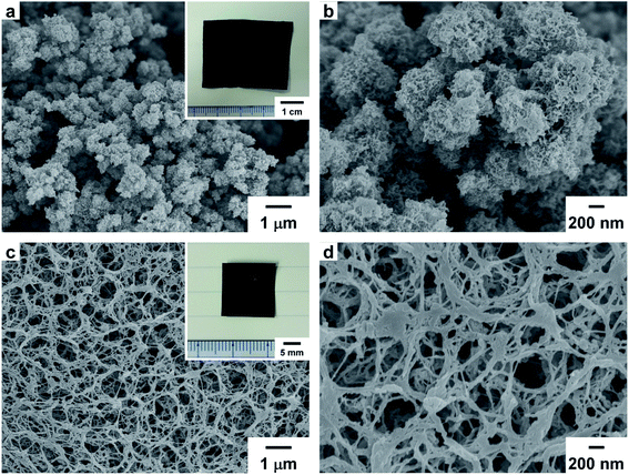
Freestanding PEDOT and PA films were obtained by polymerizing EDOT and acetylene, respectively. The inset in Fig. 1a is a photograph of the solution side of the PEDOT film with a dark blue color. The solution side of the PEDOT film and the gas side of the PA film exhibited a dull metallic luster. In contrast, the glass sides of the PEDOT and PA films exhibited a shiny metallic luster. Fig. 1a and b are scanning electron microscopy (SEM) images of the PEDOT film. The surface of the solution side of the PEDOT film exhibited a porous structure and a granular morphology in SEM images. In contrast, the glass side of the PEDOT film exhibited a wrinkled structure and a dense morphology compared with the solution side of the film (Fig. S2 in the ESI†). Fig. 1c and d are SEM images of the PA film. The surface of the gas side of the PA film had a porous morphology consisting of entangled fibrils with a subnanometer scale diameter. On the other hand, the glass side of the PA film had a densely packed structure and randomly arranged fibril morphology (Fig. S3 in the ESI†). The bulk density (dbulk) of the PA film is higher than that of the PEDOT film.2.3 TG–DTA curve for the PEDOT and PA films
The thermal behaviors of acceptor-doped PEDOT and PA films in a heating run were investigated using thermogravimetric–differential thermal analysis (TG–DTA) up to 1000 °C with a heating rate of 10 °C min−1 under flowing nitrogen or oxygen gas. In thermogravimetric analysis (TGA) measurements, the ClO4−-doped PEDOT film was stable up to 202 °C, and the major decomposition of the film occurred in the region between 202 and 388 °C (Fig. 2a). Continuous decomposition was observed in the region between 388 and 1000 °C after the major decomposition.24 The initial weight decrease (<100 °C) in the TG curve was attributed to evaporation of adsorbed moisture from the film. In the DTA curve of an iodine-doped PA film, an exothermic peak attributed to a cis–trans isomerization was observed at 129 °C. The weight of the PA film radically decreased with an increase in temperature up to 194 °C due to evaporation of the excess adsorbed iodine, as seen in the TG curve. A small decrease in weight was then observed in the range of 451–672 °C. In the DTA curve of the iodine-doped PA film, no clear endothermic peaks attributed to thermal decomposition were observed (Fig. 2b). The main purpose of iodine-doping in this study was to prevent thermal decomposition of the PA film during heat treatment and to produce a freestanding carbon film which has the precursor morphology reported previously.14–16 A TG–DTA curve for a pristine PA film ([CH]n) is shown in Fig. S5b (ESI†).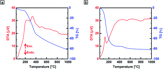 | ||
| Fig. 2 TG–DTA curves for the precursor polymer films obtained under nitrogen gas. (a) ClO4−-doped PEDOT film and (b) iodine-doped PA film ([CHI0.34]n). | ||
2.4 Carbonization of PEDOT and PA films
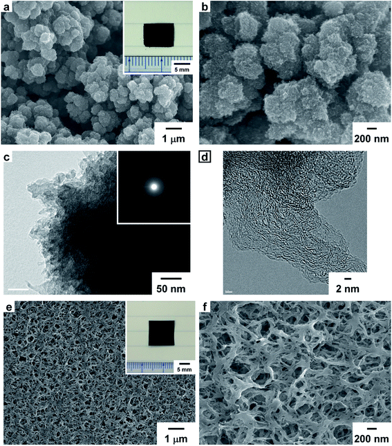
The PEDOT film was carbonized in the temperature range of 600–1100 °C using an electric furnace in flowing argon or nitrogen gas. The carbonization time and the heating rate for the carbonaceous films prepared in the temperature range of 600–1000 °C were 60 min and 10 °C min−1, respectively. For the carbonaceous film prepared at 1100 °C, the PEDOT film was first carbonized at 600 °C for 30 min, and then the carbonized film was subjected to a second thermal treatment at 1100 °C for 30 min at a heating rate of 5 °C min−1. The two-step heat-treatment procedure is hereafter called “1100 °C”. Freestanding carbonaceous films with thicknesses in the range of 64–144 μm were obtained from the PEDOT film by carbonizing in the range of 600–1100 °C (Fig. 3a, inset). The dbulk values of the carbonaceous films were lower than that of the precursor PEDOT film and decreased with an increase in the heat-treatment temperature (Fig. S7 in the ESI†). The hydrogen content of the PEDOT film carbonized at 1100 °C was lower than that of the film carbonized at 600 °C. It is worth noting that the carbonized films still include sulfur atoms even at 1100 °C. The sulfur content of the carbonized PEDOT film decreased with an increase in the heat-treatment temperature (Fig. S8a in the ESI†). Thus, the amount of heteroatoms doping could be well controlled. In contrast, the carbon content of the carbonized PEDOT film increased with an increase in the heat-treatment temperature. We have recently performed X-ray photoelectron spectroscopy (XPS) on a PEDOT-based carbon film prepared at 800 °C to investigate bonding states of the sulfur atom in the carbon film.13a From the XPS profile, the sulfur atoms are mainly found in thiophene-like structures in the present carbonaceous films. It is well-known that the electrochemical properties of carbon materials can be improved by doping them with heteroatom species, such as nitrogen, oxygen, phosphorus, boron, and sulfur. Among heteroatom-doped carbon materials, there are some examples of sulfur-doped carbon materials being used in supercapacitors.25 It has been reported that the doped carbon materials show a capacitance superior to that of undoped carbon materials. In addition, from energy dispersive X-ray spectrometry (EDS) analysis, the PEDOT-based carbonaceous film contained both oxygen and sulfur species (Fig. S9 in the ESI†).The PA film was carbonized in the range of 600–1100 °C using a method similar to the carbonization of the PEDOT film. Iodine-doping was performed before the carbonization process by exposing the film to iodine gas at room temperature for 20–28 h in a sample bottle. The amount of doped iodine in the films was determined by weighing the doped PA films. The atomic ratio of doped iodine to carbon in the PA film (I/C) was in the range of 0.17–0.32. Freestanding carbon films with thicknesses in the range of 66–76 μm were obtained by the carbonization of the PA film in the range of 600–1100 °C (Fig. 3e, inset). The dbulk values of the carbon films were higher than that of the PA film (Fig. S7 in the ESI†). On the basis of the results of elemental analysis, no iodine was detected in the carbon films prepared at temperatures higher than 800 °C. Isotropic thermal shrinkage was observed in both polymer films during heat treatment. Carbonization yields, dbulk values, elemental analyses, and σ values of the PEDOT, PA, and carbonaceous films are summarized in Table 1.
| Polymer | Heat-treatment temp. (°C) | Precursor | Carbonization yield (%) | dbulk (g cm−3) | C (wt%) | H (wt%) | S (wt%) | Cl (wt%) | σ (S cm−1) |
|---|---|---|---|---|---|---|---|---|---|
| a An untreated precursor polymer film.b Not applicable.c Data not available.d The carbon film was prepared through a carbonization of a precursor polymer film at 600 °C for 30 min and the carbonized film was further heat treated at 1100 °C for 30 min with a heating rate of 5 °C min−1.e After iodine doping. | |||||||||
| PEDOT | Rawa | [EDOT(ClO4−)0.28(H2O)0.43]n | —b | 0.52 | 40.38 | 2.75 | 18.06 | 5.53 | 1.6 × 101 |
| 600 | 34 | 0.44 | 66.79 | 1.1 | 26.4 | —c | 6.1 × 10⁻⁶ | ||
| 800 | 26 | 0.36 | 78.43 | 0.35 | 13.96 | —c | 1.4 × 10⁻¹ | ||
| 1000 | 13 | 0.34 | 91.25 | 0.22 | 5.34 | —c | 1.6 × 100 | ||
| 1100d | 35–36 (600 °C), 19–20 (1100 °C) | 0.27 | 95.03 | <0.2 | 2 | —c | 2.1 × 100 | ||
| PA | Rawa | [CH]n | —b | 0.72 | 88.27 | 7.48 | —b | —b | 3.4 × 10²e |
| 600 | [CHI0.26–0.32]n | 73–74 | 0.96 | 91.2 | 1.94 | —b | —b | 2.1 × 10⁻³ | |
| 800 | [CHI0.27–0.31]n | 70–73 | 1.13 | 93.13 | 0.67 | —b | —b | 3.8 × 101 | |
| 1000 | [CHI0.17–0.30]n | 57–66 | 0.95 | 93.5 | 0.29 | —b | —b | 9.7 × 101 | |
| 1100d | [CHI0.21–0.30]n | 70–73 (600 °C), 76–89 (1100 °C) | 0.83 | 93.07 | <0.2 | —b | —b | 9.9 × 101 | |
2.5 Morphologies of the PEDOT- and PA-based carbonaceous films
Fig. 3a and b show SEM images of the PEDOT-based carbonaceous film prepared at 1100 °C. In the SEM images of the solution side of the carbonaceous film, fine particles similar to those of the PEDOT film were observed. Fig. 3c and d show transmission electron microscopy (TEM) images of the PEDOT-based carbonaceous films. In the high-resolution TEM image, an amorphous structure in the carbonized PEDOT was observed. The amorphous carbon structure was further confirmed by using a selected-area electron-diffraction (SAED) pattern (Fig. 3c, inset), in which only diffused halos characteristic of a turbostratic carbon state were observed. Fig. 3e and f show SEM images of the gas side of the PA-based carbon film prepared at 1100 °C. An entangled fibril morphology similar to the structure of the PA film was observed on the surface of the carbon film. The hierarchical porous surface morphology of the solution side of the PEDOT-based carbonaceous film and the gas side of the PA-based carbon film should effectively adsorb a large amount of ion species during electrochemical charge and discharge processes. SEM images of the solution, gas, and glass sides of the carbonaceous films prepared at 600, 800, and 1000 °C are shown in the ESI (Fig. S10–S17†).2.6 XRD patterns of the PEDOT, PA, and carbonaceous films
Fig. 4a shows X-ray diffraction (XRD) patterns of the PEDOT film. In the pattern, a sharp (100) reflection was observed at 13.1 Å (6.7° in 2θ), and (400) and (020) reflections were observed at 3.5 Å (25.8° in 2θ). Fig. 4c shows XRD patterns of the PA film. Sharp (110) and (200) reflections were observed at 3.8 Å (23.2° in 2θ), and small (210) and (002) reflections were observed at 2.9 Å (30.9° in 2θ) and 2.2 Å (41.0° in 2θ), respectively. It is clear from the XRD patterns that the PA film has a highly crystalline region inside the fibril.26 On the other hand, in the patterns for the carbonaceous films prepared in the range of 600–1100 °C, no clear peaks were observed regardless of the heat-treatment temperature and kinds of precursor polymers in agreement with previously reported results (Fig. 4b and d).13a,16 The carbon films prepared from the PA film had slightly better degrees of crystallinity than those of the carbonaceous films prepared from the PEDOT film.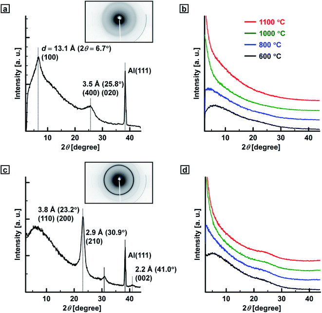 | ||
| Fig. 4 XRD patterns of the (a) PEDOT, (b) PEDOT-based carbonaceous, (c) PA and (d) PA-based carbon films. | ||
2.7 Raman scattering spectra of the PEDOT, PA, and carbonaceous films
Fig. 5 shows Raman spectra of PEDOT-based carbonaceous and PA-based carbon films. The Raman spectra for the carbonaceous films prepared at 800 °C showed broad D- and G-bands in the ranges of 1333–1336 and 1532–1559 cm−1, respectively, which is in agreement with previous results.13a,16 The D-bands for the carbonaceous films increased in intensity with an increase in the heat-treatment temperature in the range of 600–1100 °C. Raman intensity ratios of the G- and D-bands (IG/ID) and La values of the carbonaceous films are summarized in Table S1 (ESI†). The IG/ID and La values decreased with an increase in the heat-treatment temperature.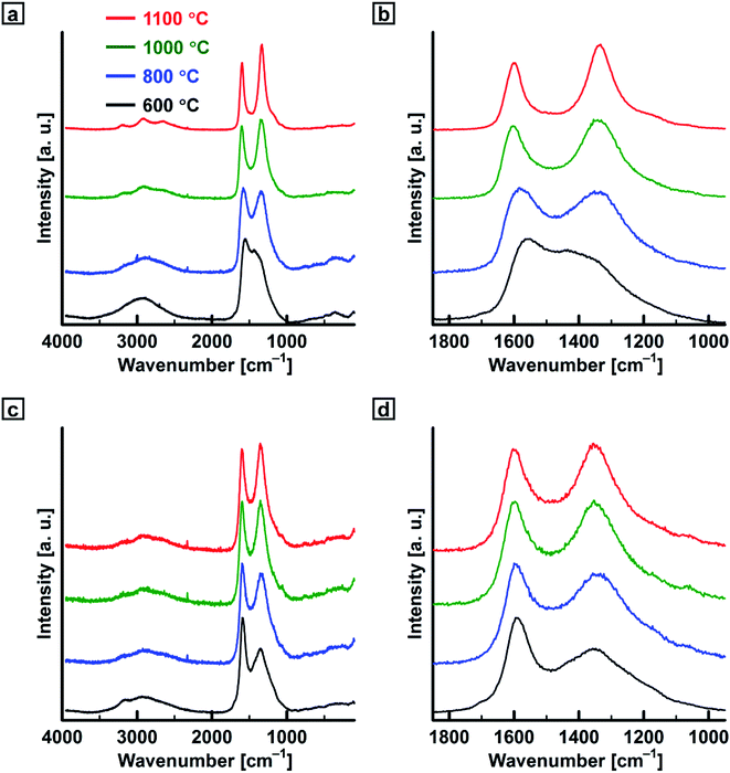 | ||
| Fig. 5 Raman scattering spectra of the (a and b) PEDOT-based carbonaceous films and (c and d) PA-based carbon films prepared in the temperature range of 600–1100 °C. | ||
2.8 Surface areas, pore volumes, and pore sizes of the PEDOT- and PA-based carbonaceous films
Fig. S21 and S22 (ESI†) show nitrogen adsorption/desorption isotherms and pore size distributions of the PEDOT-based carbonaceous films and PA-based carbon films prepared in the range of 1000–1100 °C. The PEDOT-based carbonaceous film basically exhibited a type I adsorption isotherm characteristic of microporous materials. The Brunauer–Emmett–Teller (BET) specific surface area (SBET) and micropore volume (Vmicro) of the carbonaceous film were in the ranges of 617–715 m2 g−1 and 0.22–0.26 cm3 g−1, respectively. The contents of the micropore surface area (Smicro/SBET) and volume (Vmicro/Vtotal) were determined to be 96% and in the range of 72%–85%, respectively. In contrast, the PA-based carbon film had a much lower SBET value than that of the PEDOT-based carbonaceous film. The SBET, Smicro, Vtotal, Vmicro, and average pore diameter (Daverage) values for the carbonized PEDOT are summarized in Table 2.| Polymer | Heat-treatment temp. (°C) | SBET (m2 g−1) | Smicro (m2 g−1) | Vtotal (cm3 g−1) | Vmicro (cm3 g−1) | Smicro/SBET (%) | Vmicro/Vtotal (%) | Daverage (nm) |
|---|---|---|---|---|---|---|---|---|
| PEDOT | 1000 | 715 | 689 | 0.3 | 0.26 | 96 | 85 | 1.7 |
| 1100 | 617 | 590 | 0.31 | 0.22 | 96 | 72 | 2 | |
| PA | 1000 | 17.6 | 14.6 | 0.14 | 0.39 × 10⁻² | 83 | 2.8 | 31.9 |
| 1100 | 13.9 | 10.1 | 0.12 | 0.25 × 10⁻² | 73 | 2.1 | 33.7 |
2.9 Electrical conductivities of the PEDOT, PA, and carbonaceous films
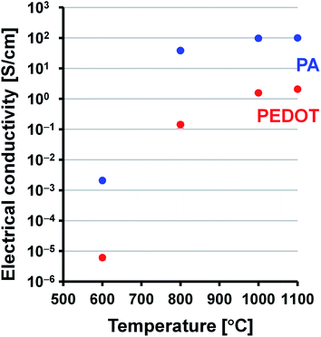
Electrical conductivities of the PEDOT, PA, and carbonaceous films were measured using a four-point probe method at room temperature. The doped PEDOT film had a conductivity of 1.6 × 101 S cm−1. The PA film with doped iodine ([CHI0.31]n) had a conductivity of 3.4 × 10² S cm−1. In contrast, the PEDOT- and PA-based carbonaceous films prepared in the range of 600–1100 °C had conductivities on the order of 10−6 to 100 S cm−1 and 10−3 to 101 S cm−1, respectively (Fig. 6). The present PEDOT- and PA-based carbonaceous films have lower electrical conductivity than doped PEDOT film and PA film with doped iodine. This is an expected result because the carbonaceous films prepared at a relatively low temperature of 600–1100 °C still contain a large amount of sp3 carbon component, implying that the films are exist in an amorphous state. Such an amorphous and low-crystalline carbon material often shows relatively low electrical conductivity. The electrical conductivities of the carbonaceous films increased with increase in the heat-treatment temperature. Note that the PEDOT and PA films carbonized at 1100 °C have approximately 5 orders and 4 orders of magnitude higher conductivities than those of the films carbonized at 600 °C do, respectively. The conductivity of the PA-based carbon film prepared at 1100 °C is approximately 48 times higher than that of the PEDOT-based carbonaceous film prepared at 1100 °C. The large difference in electrical conductivity between the carbonaceous films was attributed to the difference in the dbulk values. The PA-based carbon film has a higher dbulk value in the range of 0.83–1.13 g cm−3 than that of the PEDOT-based carbonaceous film (0.27–0.44 g cm−3), leading to the high conductivity.2.10 Cyclic voltammetry of PEDOT- and PA-based carbonaceous films
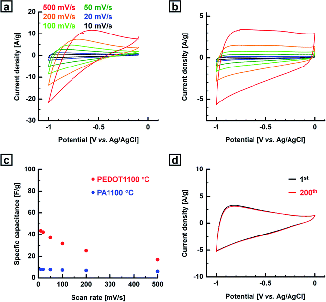
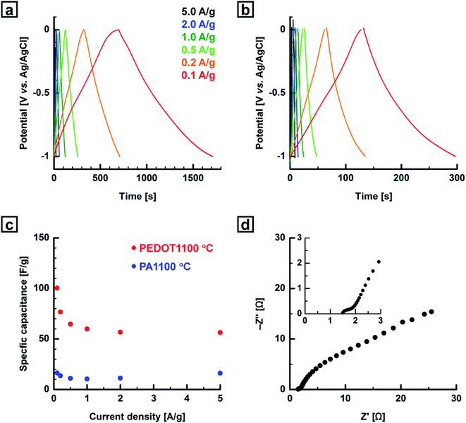
Cyclic voltammetry was performed using a three-electrode system with KCl as the electrolyte at room temperature. A Pt wire, Ag/AgCl electrode, and nickel plate were used as the counter electrode, reference, and current collector, respectively. In this work, we used the PEDOT- and PA-based carbonaceous films without any further treatment as electrode materials for the fabrication of working electrodes. The potential range and the scan rate were −1.0–0.0 V or −1.0–(−0.1) V and 10–500 mV s−1, respectively. No obvious sample damage was observed during the electrochemical experiments. Fig. 7, S23 and S25 (ESI†) show cyclic voltammograms of the PEDOT- and PA-based carbonaceous films measured at various scan rates. The cyclic voltammograms of the PEDOT and PA films carbonized in the range of 1000–1100 °C showed typical capacitive behavior with no remarkable peaks and a quasi-rectangular shape profile. The cyclic voltammograms of the carbonaceous films remained rectangular-like shape with little distortion even at a high scan rate of 500 mV s−1, indicating good rate capability. On the other hand, the cyclic voltammograms of the carbonaceous film prepared in the range of 600–800 °C showed small rectangular-like waves independent of the scan rate, corresponding to low specific capacitances. This is mainly due to the relatively low carbon content and the low electrical conductivity of the film, resulting in the poor CV performance. The specific capacitances of the PEDOT-based carbonaceous and the PA-based carbon films decreased with an increase in the scan rate. The highest specific gravimetric capacitance (Cm,CV) was recorded for the PEDOT-based carbonaceous film prepared at 1100 °C. The maximum Cm,CV values of the PEDOT-based carbonaceous films at scan rates of 10, 20, 50, 100, 200, and 500 mV s−1 were calculated from the cyclic voltammograms to be 44, 42, 37, 32, 25, and 17 F g−1, respectively. The maximum Cm,CV values of the PA-based carbon film at scan rates of 10, 20, 50, 100, 200, and 500 mV s−1 were calculated to be 7.8, 7.7, 7.5, 7.1, 6.7, and 5.9 F g−1, respectively.Although the PEDOT-based carbonaceous film has much lower electrical conductivity than the PA-based carbon film at the same heat-treatment temperature does, the former has a higher Cm,CV value than the latter. The unexpectedly low Cm,CV value of the PA-based carbon films is rationalized as follows: the main effect of the doped iodine in the PA film during the heat treatment is to prevent thermal decomposition of the film, as mentioned before. The decomposition reaction of the PA film is largely suppressed, as observed in the TG–DTA curve for the iodine-doped PA film (Fig. 2b). In other words, PA-based carbon films with relatively high electrical conductivities can be produced from the iodine-doped PA film. However, their Cm,CV values are quite low due to a lack of microporous structures and the existence of insufficient adsorption sites for electrolyte ions in the carbon film due to the large suppression of thermal decomposition during heat treatment. This lack of a microporous structure in the PA-based carbon film prepared in the range of 1000–1100 °C was confirmed by using BET measurements, as described previously (Table 2). Thus, low electrochemical performance was observed even for the PA-based carbon film prepared at the relatively high temperature of 1100 °C. However, the PEDOT films carbonized above 1000 °C undergo clear thermal decomposition, which is believed to be indispensable for the formation of micropores, resulting in the relatively high Cm,CV value of the PEDOT-based carbonaceous films in contrast to that of the PA-based carbon films. A cyclability test was performed for the PEDOT-based carbonaceous film prepared at 1000 °C with a relatively high Cm,CV value, and the cyclability test could be repeated 200 times using CV, demonstrating that the film had acceptable electrochemical stability (Fig. 7d). The shape of the cyclic voltammogram of the carbonaceous film scarcely changed, and the Cm,CV value [Cm,CV (200th) = 100% of Cm,CV (1st)] did not decrease even after 200 scans.
2.11 Galvanostatic charge and discharge curves for the PEDOT- and PA-based carbonaceous films
The GCD curves for PEDOT- and PA-based carbonaceous films were recorded at room temperature in the same potential range as that used in CV. The current density was varied from 0.1 to 5.0 A g−1. Fig. 8, S24 and S26 (ESI†) show GCD curves for the PEDOT- and PA-based carbonaceous films measured at various current densities. The PEDOT and PA films carbonized in the range of 1000–1100 °C showed more linear and triangular shape profiles than those for the films carbonized in the range of 600–800 °C, indicating ideal capacitive performance for the carbonaceous film. No significant IR drop was observed in the charge and discharge curves of the carbonaceous films even at a high current density of 5 A g−1, indicating that the films have good electrical conductivities (Fig. S27 in the ESI†). The specific capacitances of the PEDOT-based carbonaceous and the PA-based carbon films decreased with an increase in the current density. The specific gravimetric capacitances (Cm,GCD) of the carbonaceous films were calculated from the discharge curves in the potential range of −1.0–0.0 V. The PEDOT-based carbonaceous film prepared at 1000 °C was determined to have the highest Cm,GCD value of 111 F g−1 with a low current density of 0.1 A g−1. When the current density was increased to 5 A g−1, the Cm,GCD value remained at 56 F g−1, indicating a high-rate capacitive performance. In contrast, the maximum Cm,GCD values of the PA-based carbon film at current densities of 0.1, 0.2, 0.5, 1.0, 2.0, and 5.0 A g−1 were calculated to be 16, 14, 11, 10, 11, and 16 F g−1, respectively. The PA-based carbon film showed a lower Cm,GCD value than the PEDOT-based carbonaceous film did regardless of the heat-treatment temperature and current density. This agrees with the CV results. The Cm values of the carbonaceous films prepared from the PEDOT and PA films obtained from CV and GCD measurements as a function of heat-treatment temperature are summarized in Table S2 (ESI†).Fig. 8d shows a Nyquist plot for the PEDOT-based carbonaceous film prepared at 1000 °C. The equivalent series resistance (ESR) was estimated from the x-intercept of the Nyquist plot to be 1.4 Ω. The energy density of the PEDOT film carbonized at 1100 °C reached 14.0 W h kg−1 at a power density of 49.8 W kg−1. The relatively high energy density of the carbonaceous film was maintained at high power densities (Fig. S28 in the ESI†). Finally, the PEDOT-based carbonaceous films prepared in the temperature range of 1000–1100 °C exhibited relatively high Cm values not only in a neutral aqueous electrolyte solution but also in an alkaline one. Fig. S29 (ESI†) shows electrochemical behaviors of the PEDOT-based carbonaceous film prepared at 1000 °C measured by using 4 M KOH aq. as an electrolyte in the potential range from −1.0 to −0.1 V (vs. Hg/HgO). The Cm values of the carbonaceous film are summarized in Table S3 (ESI†). The highest Cm,GCD value was determined to be 69 F g−1 when the current density was 0.1 A g−1, demonstrating that the carbon material has reasonable capacitive properties even under an alkaline electrolyte conditions.
It might be fruitful to summarize advanced points of the present PEDOT-based carbonaceous film. The carbonaceous film is more advanced than active carbon mixed with binders used in supercapacitor because they require no binders/additives enabling one-step preparation without a time-consuming film-making process and their direct use as carbon electrodes in supercapacitor. In addition, aging deterioration of supercapacitors caused by mixing with binders can be effectively suppressed. On the other hand, the carbonaceous film is more advanced than other free-standing carbon-based films used in supercapacitor because they can be easily prepared via morphology-retaining carbonization of doped PEDOT films as precursors and require no further activation processes or additional treatments for the enhancement of the capacities. The carbonization precursor films can also be directly synthesized by using a very simple electrochemical polymerization procedure with a short reaction time of 1 h. Moreover, we have recently developed to produce carbonaceous and graphitic materials with hierarchical helical morphologies or highly aligned structures from electrochemically synthesized or solid-state polymerized PEDOT materials.13,20 We believe that the capacities are expected to be more enhanced than the present carbonaceous films by using the morphology-controlled carbon materials as supercapacitor electrodes owing to their ordered structures. This morphological controllability for the PEDOT-based carbon materials is also a superior point for the development of advanced supercapacitor electrodes.
3. Conclusions
It was demonstrated that carbonaceous films prepared from acceptor-doped conjugated polymer films in the range 1000–1100 °C showed good performances as supercapacitor electrodes on the basis of their high electrical conductivities and hierarchical porous morphologies. The electrochemical performance of the carbonaceous film electrodes largely depended on the heating temperature. In particular, the PEDOT film carbonized at 1000 °C exhibited the highest Cm,GCD value of 111 F g−1 at a low current density of 0.1 A g−1 determined by using GCD measurements in neutral aqueous solutions. The value is comparable to Cm values reported for cellulose-derived 2D carbon materials.11b,c,e,i To the best of our knowledge, this is the first report of PEDOT- and PA-based carbonaceous films being used as carbon electrodes for energy-storage devices. The present carbonaceous films require no binders/additives and no further activation processes or additional treatments for the enhancement of the capacities, enabling one-step preparation and their direct use as carbon electrodes in supercapacitors. The capacitive properties of the present carbonaceous films can be enhanced further by using a chemical or physical activation process.27 Moreover, the present conjugated polymer-based carbonaceous films will expand the morphological variety of supercapacitor electrode materials and could be readily used for practical applications. Finally, since conjugated polymer films synthesized through liquid crystal polymerization methods afford carbonaceous films with anisotropic structures or hierarchical helical morphologies via a morphology-retaining carbonization method,28 electrochemical investigations of the morphologically controlled carbonaceous films as advanced supercapacitor electrodes are necessary. In addition, to investigate the specific impact of the amount and type of heteroatoms on the morphology and electrochemical performance is also the main scope of the future study.Conflicts of interest
There are no conflicts to declare.Acknowledgements
We would like to thank Dr T. Takei (NIMS, Japan) for the TEM measurements and NIMS Battery Research Platform for the BET measurements. This work was supported by a Grant-in-Aid for Scientific Research (A) (No. 13370214) and that for Young Scientists (A) (No. 16H06051) from the Ministry of Education, Culture, Sports, Science and Technology, Japan. This work was partially supported by the MEXT Program for Development of Environmental Technology using Nanotechnology.References
- (a) P. Simon and Y. Gogotsi, Nat. Mater., 2008, 7, 845–854 CrossRef PubMed; (b) P. Simon and Y. Gogotsi, Acc. Chem. Res., 2013, 46, 1094–1103 CrossRef PubMed; (c) M. R. Lukatskaya, B. Dunn and Y. Gogotsi, Nat. Commun., 2016, 7, 12647 CrossRef PubMed.
- C. Liu, F. Li, L.-P. Ma and H.-M. Cheng, Adv. Mater., 2010, 22, E28–E62 CrossRef PubMed.
- Y. Zhu, S. Murali, M. D. Stoller, K. J. Ganesh, W. Cai, P. J. Ferreira, A. Pirkle, R. M. Wallace, K. A. Cychosz, M. Thommes, D. Su, E. A. Stach and R. S. Ruoff, Science, 2011, 332, 1537–1541 CrossRef PubMed.
- Y. Zhai, Y. Dou, D. Zhao, P. F. Fulvio, R. T. Mayes and S. Dai, Adv. Mater., 2011, 23, 4828–4850 CrossRef PubMed.
- H. Jiang, P. S. Lee and C. Li, Energy Environ. Sci., 2013, 6, 41–53 Search PubMed.
- X. Lu, M. Yu, G. Wang, Y. Tong and Y. Li, Energy Environ. Sci., 2014, 7, 2160–2181 Search PubMed.
- P. Pachfule, D. Shinde, M. Majumder and Q. Xu, Nat. Chem., 2016, 8, 718–724 CrossRef PubMed.
- (a) Z. Zhang, Z. Huang, L. Ren, Y. Shen, X. Qi and J. Zhong, Electrochim. Acta, 2014, 149, 316–323 CrossRef; (b) Z. Huang, Z. Zhang, X. Qi, X. Ren, G. Xu, P. Wan, X. Sun and H. Zhang, Nanoscale, 2016, 8, 13273–13279 RSC; (c) X. Liu, X. Qi, Z. Zhang, L. Ren, G. Hao, Y. Liu, Y. Wang, K. Huang, X. Wei, J. Li, Z. Huang and J. Zhong, RSC Adv., 2014, 4, 13673–13679 RSC; (d) X. Chen, G. Xu, X. Ren, Z. Li, X. Qi, K. Huang, H. Zhang, Z. Huang and J. Zhong, J. Mater. Chem. A, 2017, 5, 6581–6588 RSC.
- (a) V. L. Pushparaj, M. M. Shaijumon, A. Kumar, S. Murugesan, L. Ci, R. Vajtai, R. J. Linhardt, O. Nalamasu and P. M. Ajayan, Proc. Natl. Acad. Sci. U. S. A., 2007, 104, 13574–13577 CrossRef PubMed; (b) L. Hu, J. W. Choi, Y. Yang, S. Jeong, F. L. Mantia, L.-F. Cui and Y. Cui, Proc. Natl. Acad. Sci. U. S. A., 2009, 106, 21490–21494 CrossRef PubMed; (c) A. Izadi-Najafabadi, S. Yasuda, K. Kobashi, T. Yamada, D. N. Futaba, H. Hatori, M. Yumura, S. Iijima and K. Hata, Adv. Mater., 2010, 22, E235–E241 CrossRef PubMed; (d) Z. Niu, W. Zhou, J. Chen, G. Feng, H. Li, W. Ma, J. Li, H. Dong, Y. Ren, D. Zhao and S. Xie, Energy Environ. Sci., 2011, 4, 1440–1446 RSC.
- (a) X. Lu, H. Dou, B. Gao, C. Yuan, S. Yang, L. Hao, L. Shen and X. Zhang, Electrochim. Acta, 2011, 56, 5115–5121 CrossRef; (b) X. Yang, J. Zhu, L. Qiu and D. Li, Adv. Mater., 2011, 23, 2833–2838 CrossRef PubMed; (c) H. Gwon, H.-S. Kim, K. U. Lee, D.-H. Seo, Y. C. Park, Y.-S. Lee, B. T. Ahn and K. Kang, Energy Environ. Sci., 2011, 4, 1277–1283 RSC; (d) Z. Weng, Y. Su, D. W. Wang, F. Li, J. Du and H.-M. Cheng, Adv. Energy Mater., 2011, 1, 917–922 CrossRef; (e) H. Gao, F. Xiao, C. B. Ching and H. Duan, ACS Appl. Mater. Interfaces, 2012, 4, 7020–7026 CrossRef PubMed; (f) Z.-S. Wu, A. Winter, L. Chen, Y. Sun, A. Turchanin, X. Feng and K. Müllen, Adv. Mater., 2012, 24, 5130–5135 CrossRef PubMed; (g) F. Liu, S. Song, D. Xue and H. Zhang, Adv. Mater., 2012, 24, 1089–1094 CrossRef PubMed; (h) X. Yang, C. Cheng, Y. Wang, L. Qiu and D. Li, Science, 2013, 341, 534–537 CrossRef PubMed; (i) H.-P. Cong, X.-C. Ren, P. Wang and S.-H. Yu, Energy Environ. Sci., 2013, 6, 1185–1191 RSC; (j) Y. He, W. Chen, X. Li, Z. Zhang, J. Fu, C. Zhao and E. Xie, ACS Nano, 2013, 7, 174–182 CrossRef PubMed; (k) Z. Xiong, C. Liao, W. Han and X. Wang, Adv. Mater., 2015, 27, 4469–4475 CrossRef PubMed; (l) L. J. Wang, M. F. El-Kady, S. Dubin, J. Y. Hwang, Y. Shao, K. Marsh, B. McVerry, M. D. Kowal, M. F. Mousavi and R. B. Kaner, Adv. Energy Mater., 2015, 5, 1500786 CrossRef; (m) W. Quan, Z. L. Tang, S. T. Wang, Y. Hong and Z. T. Zhang, Chem. Commun., 2016, 52, 3694–3696 RSC; (n) Y. Shao, M. F. El-Kady, C.-W. Lin, G. Zhu, K. L. Marsh, J. Y. Hwang, Q. Zhang, Y. Li, H. Wang and R. B. Kaner, Adv. Mater., 2016, 28, 6719–6726 CrossRef PubMed; (o) H. Nishihara, T. Simura, S. Kobayashi, K. Nomura, R. Berenguer, M. Ito, M. Uchimura, H. Iden, K. Arihara, A. Ohma, Y. Hayasaka and T. Kyotani, Adv. Funct. Mater., 2016, 26, 6418–6427 CrossRef.
- (a) K. Babel and K. Jurewicz, J. Phys. Chem. Solids, 2004, 65, 275–280 CrossRef; (b) K. E. Shopsowitz, W. Y. Hamad and M. J. MacLachlan, Angew. Chem., Int. Ed., 2011, 50, 10991–10995 CrossRef PubMed; (c) L. Bao and X. Li, Adv. Mater., 2012, 24, 3246–3252 CrossRef PubMed; (d) K. Gao, Z. Shao, J. Li, X. Wang, X. Peng, W. Wang and F. Wang, J. Mater. Chem. A, 2013, 1, 63–67 RSC; (e) L. Jiang, G. W. Nelson, H. Kim, I. N. Sim, S. O. Han and J. S. Foord, ChemistryOpen, 2015, 4, 586–589 CrossRef PubMed; (f) Y. Li, J. Dong, J. Zhang, X. Zhao, P. Yu, L. Jin and Q. Zhang, Small, 2015, 11, 3476–3484 CrossRef PubMed; (g) K. Qin, J. Kang, J. Li, C. Shi, Y. Li, Z. Qiao and N. Zhao, ACS Nano, 2015, 9, 481–487 CrossRef PubMed; (h) X. Zhou, Q. Chen, A. Wang, J. Xu, S. Wu and J. Shen, ACS Appl. Mater. Interfaces, 2016, 8, 3776–3783 CrossRef PubMed; (i) L. Jiang, G. W. Nelson, S. O. Han, H. Kim, I. N. Sim and J. S. Foord, Electrochim. Acta, 2016, 192, 251–258 CrossRef.
- D. Zhu, Y. Liu, L. Yuan, Y. Liu, X. Li, L. Yi, H. Wei and K. Yao, RSC Adv., 2014, 4, 63734–63740 RSC.
- (a) S. Matsushita, B. Yan, S. Yamamoto, Y. S. Jeong and K. Akagi, Angew. Chem., Int. Ed., 2014, 53, 1659–1663 CrossRef PubMed; (b) B. Yan, S. Matsushita and K. Akagi, Chem. Mater., 2016, 28, 8781–8791 CrossRef.
- M. Kyotani, S. Matsushita, T. Nagai, Y. Matsui, M. Shimomura, A. Kaito and K. Akagi, J. Am. Chem. Soc., 2008, 130, 10880–10881 CrossRef PubMed.
- S. Matsushita, M. Kyotani and K. Akagi, J. Am. Chem. Soc., 2011, 133, 17977–17992 CrossRef PubMed.
- S. Matsushita and K. Akagi, J. Am. Chem. Soc., 2015, 137, 9077–9087 CrossRef PubMed.
- M. Goh, S. Matsushita and K. Akagi, Chem. Soc. Rev., 2010, 39, 2466–2476 RSC.
- B. Yan, S. Matsushita, K. Suda and K. Akagi, Chem. Mater., 2015, 27, 2973–2980 CrossRef.
- (a) L. Pan, G. Yu, D. Zhai, H. R. Lee, W. Zhao, N. Liu, H. Wang, B. C.-K. Tee, Y. Shi, Y. Cui and Z. Bao, Proc. Natl. Acad. Sci. U. S. A., 2012, 109, 9287–9292 CrossRef PubMed; (b) J. W. F. To, Z. Chen, H. Yao, J. He, K. Kim, H.-H. Chou, L. Pan, J. Wilcox, Y. Cui and Z. Bao, ACS Cent. Sci., 2015, 1, 68–76 CrossRef PubMed.
- B. Yan, S. Matsushita and K. Akagi, J. Mater. Chem. C, 2017, 5, 3823–3829 RSC.
- (a) Y. Kou, Y. Xu, Z. Guo and D. Jiang, Angew. Chem., Int. Ed., 2011, 50, 8753–8757 CrossRef PubMed; (b) X. Zhuang, F. Zhang, D. Wu, N. Forler, H. Liang, M. Wagner, D. Gehrig, M. R. Hansen, F. Laquai and X. Feng, Angew. Chem., Int. Ed., 2013, 52, 9668–9672 CrossRef PubMed; (c) J.-S. M. Lee, T.-H. Wu, B. M. Alston, M. E. Briggs, T. Hasell, C.-C. Hu and A. I. Cooper, J. Mater. Chem. A, 2016, 4, 7665–7673 RSC.
- X. Feng, Y. Liang, L. Zhi, A. Thomas, D. Wu, I. Lieberwirth, U. Kolb and K. Müllen, Adv. Funct. Mater., 2009, 19, 2125–2129 CrossRef.
- Z. Xiang, D. Wang, Y. Xue, L. Dai, J.-F. Chen and D. Cao, Sci. Rep., 2015, 5, 8307 CrossRef PubMed.
- (a) R. Kiebooms, A. Aleshin, K. Hutchison and F. Wudl, J. Phys. Chem. B, 1997, 101, 11037–11039 CrossRef; (b) Y. Lei, H. Oohata, S. Kuroda, S. Sasaki and T. Yamamoto, Synth. Met., 2005, 149, 211–217 CrossRef.
- (a) G. Hasegawa, M. Aoki, K. Kanamori, K. Nakanishi, T. Hanada and K. Tadanaga, J. Mater. Chem., 2011, 21, 2060–2063 RSC; (b) X. Zhao, Q. Zhang, C.-M. Chen, B. Zhang, S. Reiche, A. Wang, T. Zhang, R. Schlögl and D. S. Su, Nano Energy, 2012, 1, 624–630 CrossRef; (c) M. Seredych and T. J. Bandosz, J. Mater. Chem. A, 2013, 1, 11717–11727 RSC; (d) J. P. Paraknowitsch and A. Thomas, Energy Environ. Sci., 2013, 6, 2839–2855 RSC; (e) X. Ma, G. Ning, Y. Kan, Y. Ma, C. Qi, B. Chen, Y. Li, X. Lan and J. Gao, Electrochim. Acta, 2014, 150, 108–113 CrossRef; (f) M. Seredych, K. Singh and T. J. Bandosz, Electroanalysis, 2014, 26, 109–120 CrossRef; (g) W. Kiciński, M. Szala and M. Bystrzejewski, Carbon, 2014, 68, 1–32 CrossRef; (h) K. Singh, M. Seredych, E. R. Castellon and T. J. Bandosz, ChemElectroChem, 2014, 1, 565–572 CrossRef; (i) N. Parveen, M. O. Ansari, S. A. Ansari and M. H. Cho, J. Mater. Chem. A, 2016, 4, 233–240 RSC.
- M. Kyotani, S. Matsushita, M. Goh, T. Nagai, Y. Matsui and K. Akagi, Nanoscale, 2010, 2, 509–514 RSC.
- J. Wang and S. Kaskel, J. Mater. Chem., 2012, 22, 23710–23725 RSC.
- S. Matsushita, B. Yan and K. Akagi, Synth. Met., 2016, 216, 103–112 CrossRef.
Footnote |
| † Electronic supplementary information (ESI) available: Materials and measurements, EDOT and acetylene polymerizations, Scheme S1, Fig. S1–S30, and Tables S1–S3. See DOI: 10.1039/c8ra00267c |
| This journal is © The Royal Society of Chemistry 2018 |

