 Open Access Article
N doped carbon coated V2O5 nanobelt arrays growing on carbon cloth toward enhanced performance cathodes for lithium ion batteries†
Lijun Wuab,
Yu Zhanga,
Bingjiang Lib,
Pengxiang Wanga,
Lishuang Fanab,
Naiqing Zhang *ab and
Kening Sun*b
aState Key Laboratory of Urban Water Resource and Environment, Harbin Institute of Technology, Harbin, 150090, PR China. E-mail: znqmww@163.com
bAcademy of Fundamental and Interdisciplinary Sciences, Harbin Institute of Technology, Harbin, 150090, PR China. E-mail: sunkeninghit@163.com; Fax: +86-451-86412153; Tel: +86-451-86412153
First published on 9th February 2018
Abstract
Highly flexible, binder-free cathodes for lithium ion batteries were fabricated by utilizing N doped carbon to coat V2O5 (V2O5@N-C) nanobelt arrays growing on carbon cloth. Such a robust architecture endows the electrode with effective ion diffusion and charge transport, resulting in high rate capability (135 mA h g−1 at 10C) and excellent cycling performance (215 mA h g−1 after 50 cycles at 0.5C).
Introduction
Flexible, lightweight and environmentally friendly energy storage systems are crucial for wearable devices, smart electronics, and rollup displays.1–4 Though many various flexible electrodes have been developed, it is still a great challenge to prepare highly flexible electrodes with robust mechanical properties and outstanding electrochemical properties.5–7 Recently, many efforts have been reported on the preparation of flexible anodes for high-performance lithium ion batteries (LIBs).8–10 However, the preparation of flexible cathodes has rarely been reported because the traditional cathode materials, such as LiFePO4 and LiCoO2, are generally prepared using high temperatures, while many flexible substrates are unstable under such conditions.11,12 Therefore, it is highly desirable to prepare highly flexible cathodes with high mechanical strength and excellent electrochemical properties.Vanadium oxide (V2O5) has attracted much attention as a well-known cathode material for LIBs due to abundant sources, and higher theoretical capacity (294 mA h g−1). The high theoretical capacity of V2O5 is own to the insertion of two lithium ions during 4.0–2.0 V (vs. Li/Li+), which is much higher than LiCoO2 (140 mA h g−1) and LiFePO4 (170 mA h g−1).13–16 However, the extensive application of V2O5 is limited to its poor structural stability, low electrical conductivity, and low diffusion coefficient of Li+. To overcome these drawbacks, numerous researches have been put in effort.13–15,17,18
Currently, various nanostructures of V2O5 such as spheres, flowers and nanowires have been reported.15,19–21 Such structures own large electrode–electrolyte contact areas and short ion diffusion paths, which are beneficial for the transport of Li+. However, in order to fabricate electrodes, powder materials are usually mixed with binder and electrical conductor agent, which don't contribute to the lithium storage. Moreover, the auxiliary materials decrease the accessible area of the V2O5 nanomaterial for Li+ and cause the severe electrochemical polarization.22,23
In this work, self-supported N doped carbon coated V2O5 nanobelt arrays directly grow on a flexible carbon cloth (noted as V2O5@N-C) through a template-free hydrothermal method and followed calcination. The novel flexible and binder-free electrode is directly used as LIBs cathode. The V2O5@N-C nanobelt arrays show excellent electrochemical performances, which deliver a specific capacity of 215 mA h g−1 after 50 cycles at 0.5C (1C = 294 mA h g−1) and a specific capacity of 135 mA h g−1 at a current density of 10C.
Results and discussion
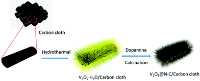
As illustrated in Scheme 1, the V2O5@N-C array was fabricated via hydrothermal route and subsequent calcination. The detail is shown in ESI.† The areal loading of V2O5@N-C in the electrode is about 1.2 mg cm−2. The X-ray diffraction (XRD) was used to characterize crystal structures of the precursor samples. The XRD patterns of the precursor samples (ESI, Fig. S1†) show an orthorhombic structure, which match with the V3O7 (JCPDS card no. 18-1453). Subsequent calcination of the V3O7 at 400 °C for 2 h in flowing argon results in the formation of V2O5. Fig. 1 shows the crystal structure of the obtained V2O5. It shows that all the diffraction peaks of calcinated sample are well indexed to the orthorhombic V2O5 (JCPDS card no. 41-1426) structure without visible impurity. Furthermore, the dopamine coated doesn't change the crystal of V2O5.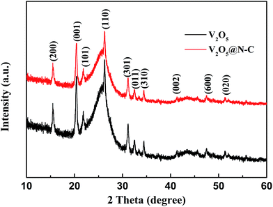 | ||
| Fig. 1 The XRD patterns of the V2O5 scraped from the as-prepared V2O5 on carbon cloth, indicating the successful preparation of V2O5. | ||
The oxidation state of vanadium was confirmed by the X-ray photoelectron spectroscopy (XPS). The spectrum (Fig. S2, ESI†) reveals the peak at 517.7 eV, 530.6 eV corresponding with V 2p3/2 and the O 1s for the V (5+)-O stretch, which is similar with the previous report.24 The peak of N 1s is obviously observed in the XPS survey spectrum of V2O5@N-C and the XPS spectrum of N 1s is provided in Fig. S2c,† which confirmed the N doping of carbon.
The calcinated samples deliver good retention of the nanobelt arrays structure, which are carried out by scanning electron microscope (SEM) and transmission electron microscope (TEM). The SEM images of carbon cloth and V2O5 array is shown in Fig. S3 and S4,† 2a. N doped carbon coated V2O5 arrays (Fig. 2b) are similarly to V2O5 arrays (Fig. 2a), which show excellent nanobelt arrays structure. TEM images (Fig. 2c and d) show that the V2O5 nanobelt is about 100 nm width and covered with a 10 nm carbon layer. The high resolution TEM (HRTEM) image (Fig. 2e) displays that it is single crystalline. The special lattice fringe matches with spacing value of 0.204 nm, corresponding to the (202) planes of the orthorhombic V2O5. The selected area electron diffraction (SAED) further confirms the single crystalline of the V2O5 nanobelt arrays (Fig. 2f). The specific surface area of V2O5 is calculated to be 18.6 m2 g−1 from the Brunauer–Emmett–Teller analysis of nitrogen adsorption–desorption isotherms in Fig. S5.†
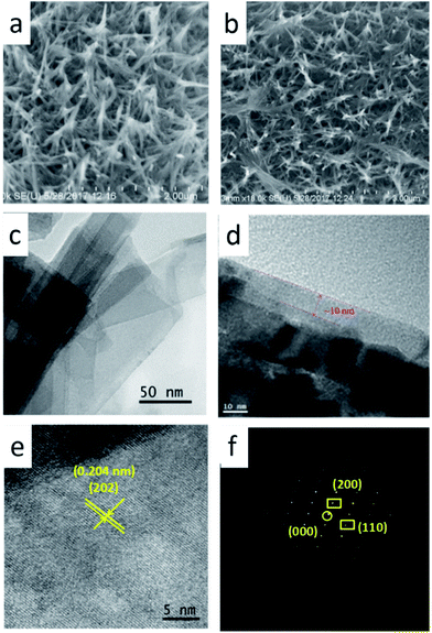 | ||
| Fig. 2 (a, b) High-magnification FESEM image. (c, d) High-magnification TEM image of V2O5@N-C. (e) HRTEM image of the product. (f) Corresponding electron diffraction pattern of the V2O5. | ||
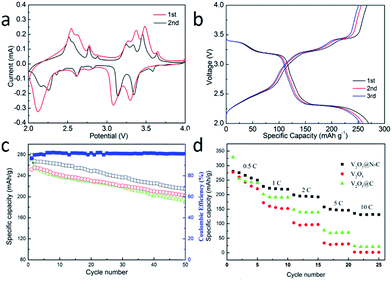
The cyclic voltammograms (CVs) curve of the V2O5@N-C at 0.2 mV s−1 during 4.0 to 2.01 V is shown in Fig. 3a. Three dominant cathodic peaks located at 2.15, 3.16 and 3.38 V are observed in the samples, which correspond to the phase transition to the γ (Li2.0V2O5), δ (Li1.0V2O5) and ε (Li0.5V2O5), respectively.25 The reduction peaks appearing around 3.38 and 3.16 V correspond to the first lithium ion intercalation the V2O5 crystal:
| V2O5 + 0.5Li+ + 0.5e− ↔ Li0.5V2O5 | (1) |
| Li0.5V2O5 + 0.5Li+ + 0.5e− ↔ LiV2O5 | (2) |
The reduction peak appearing around 2.15 V corresponds to the second lithium ion intercalation into the V2O5 crystal:
| LiV2O5 + Li+ + e− ↔ Li2V2O5 | (3) |
Three dominant anodic peaks located at around 2.50, 3.30 and 3.50 V can be attributed to the extraction of the two lithium ions with the formation of LiV2O5, Li0.5V2O5 and V2O5, respectively. While other minor redox peaks around 3.6 V and shoulder peaks located at 2.60 and 3.20 V are contributed to the structural changes.
Galvanostatic current charge–discharge profiles of sample (Fig. 3b) are carried out at 0.2C (1C = 294 mA g−1) with 2.01 V to 4.0 V. The constant current charge–discharge curves present three distinguished plateaus in each charge and discharge process, which correspond to the redox peaks and the electrochemical reactions in the CV curves. The V2O5@N-C electrode shows the initial discharge and charge capacities of 269 and 267 mA h g−1, corresponding to an initial coulombic efficiency of 99%.
Fig. 3c displays cyclic performances of the electrode materials at 0.5C. After 50 cycles, V2O5 has a specific capacity of 189 mA h g−1 with a capacity retention of 70% compared with the initial capacity. Meanwhile, the V2O5@N-C nanobelt arrays show excellent electrochemical performances, which deliver a specific capacity of 215 mA h g−1 after 50 cycles with a capacity retention of 80%. In order to further confirm the advantage of N doped carbon coating, carbon coated V2O5 arrays without N doping (V2O5@C) were prepared and tested. The cycling stability of V2O5@C is similar with V2O5. The specific capacity and capacity retention of V2O5@N-C is better than V2O5 arrays which can be attributed to the N doped carbon coated.
Considering the rate capability is one of the important parameter to measure electrochemical performance of LIBs.26 The rate capability of V2O5@N-C nanobelt arrays were tested. From Fig. 3d, it can be seen that the capacity decreases from 269, 217, 193 to 146 mA h g−1 with the current density decrease from 0.5, 1.0, 2.0 to 5.0C. Even at 10.0C, the V2O5@N-C nanobelt arrays still achieve a high capacity of 135 mA h g−1, which is higher than the previously reported values for V2O5 materials.27,28 On the other hand, the capacities of V2O5@C and V2O5 at high current densities are much lower than V2O5@N-C. The better rate capability of V2O5@N-C further confirmed the advantages of N doped carbon coating.
To further understand the reason for the enhanced electrochemical properties of V2O5@N-C. The capacitive contribution was calculated by different scan rate. Fig. 4a shows the cyclic voltammograms curves with different scan rate and pseudocapacitive capacity ratio (Fig. 4b). As shown in Fig. 4b, the ratio of the lithium storage capacity of V2O5@N-C was 94%, 90%, 83% and 76%, respectively with the scan rate 0.1, 0.2, 0.5 and 1.0 mV s−1. The ratio of capacitance for V2O5@N-C is increased with the increase of scan rate, which is beneficial for the performance of V2O5@N-C electrode material. The EIS (Fig. S6†) shows that a smaller Rct is able to realize the effective use of cathode, even in the case of high rate discharge.
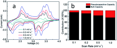 | ||
| Fig. 4 (a) CV curves of the V2O5@N-C at a different scan rate. (b) The histogram for the different ratio of pseudocapacitive and lithium storage capacity. | ||
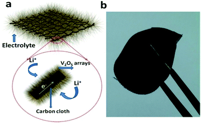
Scheme 2a shows the operating principles of the rechargeable LIBs based on the V2O5@N-C nanobelt arrays. The high capacity, good rate and impressive cycling stability performance could be ascribed to the particular structure of V2O5@N-C nanobelt arrays on the following reasons: (1) the V2O5 nanobelt arrays are strongly bound to the carbon cloth so that they have outstanding electronic conductivity. While the traditional electrode materials are usually exfoliated from the current collectors with ongoing cycling.27,29 (2) The V2O5 nanobelt arrays have the loose textures and open spaces between neighbouring nanobelt arrays, thus enhancing the electrolyte-V2O5@N-C contact area, which provides ideal conditions for quick access of the electrolyte so as to realize the higher efficiency of lithiation and delithiation with the adequate electrolyte participation. (3) Nanobelt arrays deliver excellent elastic feature, so the pulverization and fragmentation to the electrode while assembling batteries can be sufficiently avoided, which is favourable for boosting the electrochemical performances.30,31 (4) The nanoarrays structure shortens the Li+ diffusion paths and improves the rate capacity. Scheme 2b shows a photographic image of the V2O5 nanobelt arrays growing on carbon cloth, delivering excellent flexibility. It can be facile rolled up periodically, indicating the possible application in flexible devices.
Conclusion
In summary, V2O5 nanobelt arrays growing on flexible carbon cloth have been successfully prepared with a simple hydrothermal method followed by calcination in argon. These flexible, binder-free cathodes materials show an excellent electrochemical performance with outstanding cyclic stability and desirable rate performance. The V2O5@N-C nanobelt arrays cathodes deliver a specific capacity of 215 mA h g−1 after 50 cycles at 0.5C and a specific capacity of 135 mA h g−1 at 10C. V2O5 nanobelt arrays on carbon cloth could become a promising candidate for flexible LIBs cathode materials due to its excellent electrochemical performance and high mechanical strength.Conflicts of interest
There are no conflicts to declare.Acknowledgements
This work was supported by the National Natural Science Foundation of China (no. 21646012), the State Key Laboratory of Urban Water Resource and Environment, Harbin Institute of Technology (no. 2016DX08), China Postdoctoral Science Foundation (no. 2016M600253, 2017T100246), and the Postdoctoral Foundation of Hei long jiang Province, the Fundamental Research Funds for the Central Universities (grant no. HIT. NSRIF. 201836).Notes and references
- H. Nishide and K. Oyaizu, Science, 2008, 319, 737–738 CrossRef CAS PubMed.
- L. Nyholm, G. Nyström, A. Mihranyan and M. Strømme, Adv. Mater., 2011, 23, 3751–3769 CAS.
- J. A. Rogers, T. Someya and Y. Huang, Science, 2010, 327, 1603–1607 CrossRef CAS PubMed.
- P. P. Prosini, R. Mancini, L. Petrucci, V. Contini and P. Villano, Solid State Ionics, 2001, 144, 185–192 CrossRef CAS.
- J. Liu, J. Sun and L. Gao, Nanoscale, 2011, 3, 3616–3619 RSC.
- K. Wang, S. Luo, Y. Wu, X. He, F. Zhao, J. Wang, K. Jiang and S. Fan, Adv. Funct. Mater., 2013, 23, 846–853 CrossRef CAS.
- H. Yu, C. Zhu, K. Zhang, Y. Chen, C. Li, P. Gao, P. Yang and Q. Ouyang, J. Mater. Chem. A, 2014, 2, 4551–4557 CAS.
- K. Fu, O. Yildiz, H. Bhanushali, Y. Wang, K. Stano, L. Xue, X. Zhang and P. D. Bradford, Adv. Mater., 2013, 25, 5109–5114 CrossRef CAS PubMed.
- B. Liu, J. Zhang, X. Wang, G. Chen, D. Chen, C. Zhou and G. Shen, Nano Lett., 2012, 12, 3005–3011 CrossRef CAS PubMed.
- Q.-Q. Xiong, J.-P. Tu, X.-H. Xia, X.-Y. Zhao, C.-D. Gu and X.-L. Wang, Nanoscale, 2013, 5, 7906–7912 RSC.
- X. Jia, Z. Chen, A. Suwarnasarn, L. Rice, X. Wang, H. Sohn, Q. Zhang, B. M. Wu, F. Wei and Y. Lu, Energy Environ. Sci., 2012, 5, 6845–6849 CAS.
- X. Jia, C. Yan, Z. Chen, R. Wang, Q. Zhang, L. Guo, F. Wei and Y. Lu, Chem. Commun., 2011, 47, 9669–9671 RSC.
- A. Ghosh, E. J. Ra, M. Jin, H. K. Jeong, T. H. Kim, C. Biswas and Y. H. Lee, Adv. Funct. Mater., 2011, 21, 2541–2547 CrossRef CAS.
- Y. Li, J. Yao, E. Uchaker, M. Zhang, J. Tian, X. Liu and G. Cao, J. Phys. Chem. C, 2013, 117, 23507–23514 CAS.
- H. Yu, X. Rui, H. Tan, J. Chen, X. Huang, C. Xu, W. Liu, Y. Denis, H. H. Hng and H. E. Hoster, Nanoscale, 2013, 5, 4937–4943 RSC.
- J. Xu, H. Sun, Z. Li, S. Lu, X. Zhang, S. Jiang, Q. Zhu and G. S. Zakharova, Solid State Ionics, 2014, 262, 234–237 CrossRef CAS.
- H. Li, J. Wang, X. Liu, Q. Sun, A. B. Djurišić, M. Xie, Y. Mei, C. Y. Tang and K. Shih, RSC Adv., 2017, 7, 2480–2485 RSC.
- S. Liang, Y. Hu, Z. Nie, H. Huang, T. Chen, A. Pan and G. Cao, Nano Energy, 2015, 13, 58–66 CrossRef CAS.
- H. Liu and W. Yang, Energy Environ. Sci., 2011, 4, 4000–4008 CAS.
- A. Q. Pan, H. B. Wu, L. Zhang and X. W. D. Lou, Energy Environ. Sci., 2013, 6, 1476–1479 CAS.
- C. Zhang, Z. Chen, Z. Guo and X. W. D. Lou, Energy Environ. Sci., 2013, 6, 974–978 CAS.
- Y. Wang, H. J. Zhang, W. X. Lim, J. Y. Lin and C. C. Wong, J. Mater. Chem., 2011, 21, 2362–2368 RSC.
- Q.-Q. Xiong, J.-P. Tu, Y. Lu, J. Chen, Y.-X. Yu, X.-L. Wang and C.-D. Gu, J. Mater. Chem., 2012, 22, 18639–18645 RSC.
- Y. Liu, M. Clark, Q. Zhang, D. Yu, D. Liu, J. Liu and G. Cao, Adv. Energy Mater., 2011, 1, 194–202 CrossRef CAS.
- X. Zhou, G. Wu, J. Wu, H. Yang, J. Wang and G. Gao, Phys. Chem. Chem. Phys., 2014, 16, 3973–3982 RSC.
- Y. Li, B. Tan and Y. Wu, Nano Lett., 2008, 8, 265–270 CrossRef CAS PubMed.
- J. Shin, H. Jung, Y. Kim and J. Kim, J. Alloys Compd., 2014, 589, 322–329 CrossRef CAS.
- S. Wang, Z. Lu, D. Wang, C. Li, C. Chen and Y. Yin, J. Mater. Chem., 2011, 21, 6365–6369 RSC.
- J. Cheng, B. Wang, H. L. Xin, G. Yang, H. Cai, F. Nie and H. Huang, J. Mater. Chem. A, 2013, 1, 10814–10820 CAS.
- D. Chao, X. Xia, J. Liu, Z. Fan, C. F. Ng, J. Lin, H. Zhang, Z. X. Shen and H. J. Fan, Adv. Mater., 2014, 26, 5794–5800 CrossRef CAS PubMed.
- A. K. Mondal, D. Su, S. Chen, X. Xie and G. Wang, ACS Appl. Mater. Interfaces, 2014, 6, 14827–14835 CAS.
Footnote |
| † Electronic supplementary information (ESI) available. See DOI: 10.1039/c7ra13633a |
| This journal is © The Royal Society of Chemistry 2018 |

