 Open Access Article
Establishment of a highly efficient flame-retardant system for rigid polyurethane foams based on bi-phase flame-retardant actions
Xingxing Shia,
Saihua Jiang *ab,
Jingyi Zhua,
Guohui Lib and
Xiangfang Peng*a
aSchool of Mechanical and Automotive Engineering, South China University of Technology, Wushan Road 381, Guangzhou, 510641, P. R. China. E-mail: meshjiang@scut.edu.cn; pmxfpeng@scut.edu.cn; mezcl@scut.edu.cn; Fax: +86-20-22236321; Fax: +86-20-87112503; Tel: +86-13678970588 Tel: +86-20-87111143 Tel: +86-18822182920
bTianjin Fire Research Institute of Ministry of Public Security, Tianjin 300381, China
First published on 12th March 2018
Abstract
Rigid polyurethane foam (PU), one of the most promising wall insulation materials, exhibits high flammability and fire risk. In this work, PU/EG/HQ composites with highly effective flame retardancy were fabricated by adding two kinds of flame retardants, expandable graphite (EG) and 10-(2,5-dihydroxyphenyl)-10-hydro-9-oxa-10-phosphorylphenanthrene-10-oxide (DOPO-HQ), during the synthesis of polyurethane. Thermal stability and flammability were evaluated using the limiting oxygen index (LOI), thermogravimetric analysis (TGA), UL-94 vertical flame results, and cone colorimeter tests. The as-synthesized PU/EG/HQ composites showed a high LOI value, a maximum peak heat release rate (PHRR) value which was decreased by 58.5% and an increased char yield at 800 °C. They also achieved UL-94 V-0 classification. SEM and Raman spectra indicated that the “worm-like” intumescent char layer with a graphitized structure and the formed viscous liquid film were vital factors in the enhancement of the flame retardancy of polyurethane foam in the condensed phase. TG-IR results show that the release of toxic volatiles and flammable gases from the PU/EG/HQ samples was remarkably decreased compared with the release from pure PU. This work associates a gas–solid biphase flame retardancy mechanism with the incorporation of two types of flame retardant and presents an effective method for the synthesis of bi-phase flame-retardant polymers.
1. Introduction
Rigid polyurethane foam (PU) possesses unparalleled advantages in the field of thermal insulation materials due to its low heat conductivity, abrasion resistance, light weight, and energy efficiency.1–3 Although it is one of the most promising wall insulation materials, polyurethane foam easily catches fire and has a fast flame propagation speed and a relatively low limiting oxygen index value.4,5 Moreover, the toxic gases that escape during combustion threaten people’s property as well as their lives.6The most prevalent technique to reinforce the fire-resistance performance of polyurethane foam is to blend additive flame retardants into the foam matrix at the synthesis stage. This method is operationally simple, low cost and perfect for large-scale manufacture. In recent years, expandable graphite (EG), a representative intumescent flame retardant, has attracted much interest due to its excellent expansibility, high temperature resistance and thermal insulation. EG can form an intumescent carbonaceous layer at high temperatures and the expanded char can then cover a substrate surface to restrain heat and mass transfer, acting as a vital part in condensed-phase flame retardancy.7,8 However, poor dispersion and interfacial compatibility between EG and matrices sometimes restrict its applications.9 Under the influence of flame pressure or heat convection, the “worm-like” char produced by EG can easily fall off the foam surface, which is known as the “popcorn effect”.10 Moreover, the migration and precipitation phenomenon of EG seriously affects the anti-flame durability over long periods of use.
In recent years, a novel phosphorus-based flame retardant, 10-(2,5-dihydroxyphenyl)-10-hydro-9-oxa-10-phosphorylphenanthrene-10-oxide (DOPO-HQ, abbreviated as HQ) has attracted considerable attention on account of its high thermal stability and good resistance to oxidation and water.11,12 HQ can be introduced into the backbone structure of polyurethane at the compounding stage in a reactive manner. HQ was originally adapted for epoxy thermosets and exhibits prominent flame-retardant properties in the gas phase.13–15 In addition, HQ can produce active PO˙ radicals during its decomposition, which are capable of reacting with H˙ and OH˙ radicals during the combustion process of the matrix to decrease heat release, prevent further oxidation and consequently suppress flame propagation.16,17 Besides, the incorporation of HQ into polyurethane can improve the flame retardancy without changing the structure of the matrix, and there is no long-term migration phenomenon. Hence, HQ can partially replace EG to reduce the EG loading and ensure flame retardancy.
In this work, EG and HQ were incorporated during polyurethane synthesis to obtain highly effective flame-retardant PU/EG/HQ samples. The thermal decomposition behaviour and flammability of the PU/EG/HQ composites were evaluated using TGA, the LOI, a UL-94 vertical combustion test and cone colorimeter tests. SEM and Raman spectroscopy of the char residue were conducted to explore the fire-retardancy mechanism in the condensed phase. The gas-phase flame-retardancy mechanism of polyurethane was also analysed by detecting the volatilization of flammable gases in a TG-IR test.
2. Experimental section
2.1 Materials
Diphenyl methane diisocyanate (MDI5005, NCO = 30.75%) and polyether polyols 4110 (hydroxyl value: 430 mg KOH g−1, viscosity: 2500–4000 mPa s at 25 °C) were supplied by Guangzhou Hongna Chemical Co., Ltd (Guangzhou, China). Expandable graphite (80 mesh) was provided by Qingdao Hengrunda Graphite Products Co., Ltd (Qingdao, China). The foam stabilizing silicone oil and A33 catalyst (33 wt% triethylene diamine solution) were also obtained from Guangzhou Hongna Chemical Co., Ltd (Guangzhou, China). The blowing agent, deionized water, was purchased from Guangzhou Qianhui Chemical Glass Instrument Co., Ltd. (Guangzhou, China). 10-(2,5-Dihydroxyphenyl)-9,10-dihydro-9-oxa-10-phosphaphenanthrene10-oxide (HQ) was purchased from Zhengzhou Alpha Chemical Co., Ltd (Zhengzhou, China).2.2 Fabrication of flame-retardant PU/EG/HQ composites
The flame-retardant polyurethane (FRPU) samples were prepared by a one-pot and free-rise procedure. Polyols, silicone oil, distilled water and A33 were weighed and then mixed in a 500 mL plastic beaker using a high speed electric mixer (JBQ-D1355) to obtain mixture A. EG, HQ and MDI were blended in another plastic beaker to gain mixture B. Mixture B was rapidly added to mixture A and stirred at 20![[thin space (1/6-em)]](https://www.rsc.org/images/entities/char_2009.gif) 000 r for 10 seconds, then at once fed into an open plastic mold (225 × 165 × 70 mm3) to prepare free-rise foam. Finally, the foam was cured at 70 °C for 24 h. The NCO/OH ratio was 1.05. The optimal formulations of pure FRPU are shown in Table 1 and the compositions of the PU/EG/HQ composites are illustrated in Table 2.
000 r for 10 seconds, then at once fed into an open plastic mold (225 × 165 × 70 mm3) to prepare free-rise foam. Finally, the foam was cured at 70 °C for 24 h. The NCO/OH ratio was 1.05. The optimal formulations of pure FRPU are shown in Table 1 and the compositions of the PU/EG/HQ composites are illustrated in Table 2.
| Sample | PU (wt%) | EG (wt%) | HQ (wt%) | Density (g cm−3) | UL-94 | LOI (%) |
|---|---|---|---|---|---|---|
| PU | 100 | — | — | 0.073 | NR | 19.2 |
| PU-25EG | 75 | 25 | — | 0.084 | V-0 | 36.7 |
| PU-20EG | 80 | 20 | — | 0.075 | V-0 | 35.1 |
| PU-15EG | 85 | 15 | — | 0.077 | V-0 | 30.5 |
| PU-14EG-1HQ | 85 | 14 | 1 | 0.074 | V-0 | 28.5 |
| PU-12EG-3HQ | 85 | 12 | 3 | 0.072 | V-0 | 28.8 |
| PU-10EG-5HQ | 85 | 10 | 5 | 0.070 | V-0 | 28.7 |
2.3 Characterization
A UL-94 vertical flame test was carried out on a CFZ-2-type instrument (Jiangning Analysis Instrument Company, China) according to ASTM D635-14 standards. The dimensions of the specimens were 127 × 13 × 10 mm3.LOI values were measured using a JF-4 oxygen index meter (Jiangning Analysis Instrument Company, China) according to GB/T 2406.2-2009. The dimensions of the specimens were 127 × 10 × 10 mm3.
The apparent density was measured using a DH-600 electronic densimeter (Shenzhen Dahong Metalloy Density Measuring Instrument Company, China) according to GB/T 6343–2009 standards, with a specimen bar cut to the dimensions of 50 × 30 × 5 mm3.
Cone colorimeter tests were carried out using a cone calorimeter (FTT) at a heat flux of 35 kW m−2 with specimen dimensions of 100 × 100 × 25.0 mm3 according to ISO 5660-1 standards.
TGA was analyzed using a TGA 209F3 IR thermal gravimetric analyzer (Netzsch, Germany) from 25 °C to 800 °C at a heating rate of 20 °C min−1 under N2 and air flow.
SEM images were taken using a scanning electron microscope (FEI Quanta FEG 250) at an accelerating voltage of 5.0 kV.
Raman spectroscopy was performed using a RAMANLOG 6 laser Raman Spectrometer (SPEX-1403, USA) with an argon laser of 514.5 nm in a wavelength range of 2000–800 cm−1.
The TG-IR test was carried out using a TGA STA449C IR thermogravimetric analyzer (Netzsch, Germany), which was interfaced to a Tensor27 FTIR spectrophotometer (Bruker, Germany).
3. Results and discussion
3.1 Flame retardancy
The PU/EG/HQ samples were examined using UL-94 and LOI tests in order to assess their flammability properties and these results are summarized in Table 2. PU has a comparatively low LOI value of 19.2% and burns heavily and all samples can reach the UL-94 V-0 grade with the presence of EG or EG/HQ. As illustrated in Table 2, the incorporation of 15 wt% EG into neat PU leads to a large increase in the LOI value from 19.2% to 30.5% and LOI values are increased further with the increased loading of EG. However, settlement behaviour and poor dispersion were observed during the premixing procedure when a high volume of EG (≥15 wt%) was added into PU, resulting in a deterioration of processing performance in industrial production.18 HQ was introduced into the PU/EG system to lessen the amount of EG without compromising the fire-resistant properties. The PU/EG/HQ samples can achieve a V-0 rating and still demonstrate much higher LOI values than PU with a total amount of 15 wt%. This result suggests that the as-fabricated PU/EG/HQ composites display heightened fire resistance with the combination of EG and HQ in comparison with PU.The densities of the PU/EG/HQ samples are also expressed in Table 2. A slight increase in foam density can be seen with increasing EG content, attributed to the large size of the EG particles embedded in the cell wall. When EG particles are partially replaced with HQ particles of a smaller size, PU/EG/HQ foam density decreases gradually with increased HQ loading.
Cone calorimetry tests were used to simulate the combustion behaviour of a real fire hazard, and the optical photos of the PU/EG/HQ composites after the cone calorimeter test are shown in Fig. 1a. It can be found that only a small amount of smooth char residue remained in the pure PU, while “worm-like” intumescent and dense char was left after the addition of EG or EG/HQ. Fig. 1b and c reveal the heat release rate and total heat release curves of the PU/EG/HQ composites, and the detailed data are presented in Table 3. The maximum peak heat release rate (PHRR) and total heat release (THR) values for neat PU are 310 kW m−2 and 40.7 MJ m−2, respectively. When EG and HQ were incorporated into the system, the time to reach the PHRR (t-PHRR) reduced from 45 s to 25 s due to the catalytic degradation of EG and HQ. Compared with PU, the PHRR value of the PU-10EG-5HQ sample shifted to a lower value and decreased by 58.5%. However, the addition of EG and HQ had little effect on the THR value. As a result, the intumescent char layer is beneficial to the reduction of the PHRR value and the PU/EG/HQ composites exhibit better fire-resistance performance and heat inhibition effects.
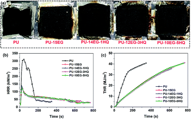 | ||
| Fig. 1 (a) Optical photos of the PU/EG/HQ samples after the cone calorimeter test; (b) heat release rate, and (c) total heat release curves of the PU/EG/HQ composites. | ||
| Sample | t-PHRR (s) | PHRR (kW m−2) | THR (MJ m−2) |
|---|---|---|---|
| a PHRR: the maximum peak heat release rate, t-PHRR: the time to reach PHRR, and THR: total heat release. | |||
| PU | 45 | 310.0 | 40.7 |
| PU-15EG | 25 | 123.4 | 37.3 |
| PU-14EG-1HQ | 20 | 140.8 | 35.9 |
| PU-12EG-3HQ | 25 | 130.3 | 41.2 |
| PU-10EG-5HQ | 25 | 128.5 | 40.7 |
3.2 Thermal properties analysis
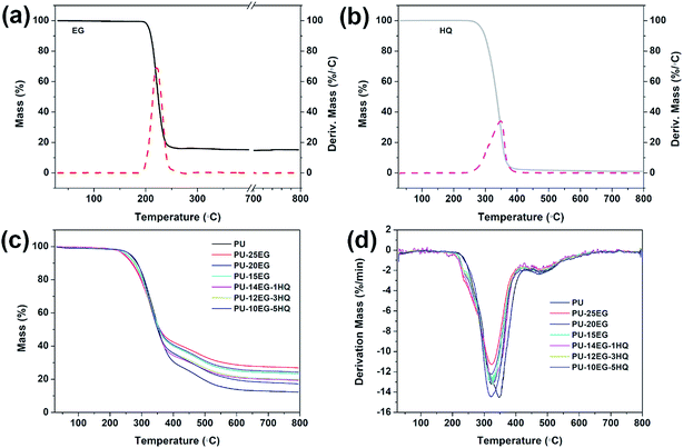
The TGA/DTG curves for the PU/EG/HQ composites under a N2 atmosphere are shown in Fig. 2, and the related data is illustrated in Table 4. The main decomposition of pure PU at 200–400 °C is ascribed to the depolycondensation reaction of polyurethanes to produce precursors such as polyols and isocyanates.19,20 Then the isocyanates are dimerized to form carbodiimides, accompanied by the volatilization of small molecule compounds such as carbon oxides, alcohols, amines, aldehydes, etc.21 The second degradation stage at 400–800 °C is primarily the degradation of substituted urea resulting from the reaction of carbodiimide with alcohol or water.22 In the presence of EG, both the T5% and the Tmax1 of the PU/EG composites are shifted to a lower value compared with pure PU and decrease with increasing EG loading. This may be caused by the early degradation of EG with a Tmax1 value of 220.1 °C (shown in Fig. 1a). Besides, the char yields of the PU/EG samples are raised with increased EG content. As can be observed in Table 4, with the incorporation of HQ into the PU/EG system, the T5% of the PU/EG/HQ sample is moved to a higher value from 247 °C for PU-14EG-1HQ to 265 °C for PU-10EG-5HQ as a result of the high initial degradation temperature of HQ. The maximum increase of char residue in the PU/EG/HQ samples is enhanced from 12.3 wt% for PU to 19.9 wt% for PU-12EG-3HQ, which is much lower than that of the PU-15EG samples.| Samples | T5% (°C) | Tmax1 (°C) | Tmax2 (°C) | CR at 800 °C (wt%) |
|---|---|---|---|---|
| a T5%: the temperature at 5 wt% weight loss (defined as the initial degradation temperature), Tmax1/Tmax2: the temperature at the first/second maximum weight loss rate, CR: the solid residual char yields. | ||||
| PU | 263 | 347.3 | 473.5 | 12.3 |
| PU-25EG | 244 | 323.9 | 482.6 | 26.9 |
| PU-20EG | 252 | 321.7 | 472.2 | 24.3 |
| PU-15EG | 254 | 328.8 | 480.6 | 23.3 |
| PU-14EG-1HQ | 247 | 326.8 | 470.8 | 19.4 |
| PU-12EG-3HQ | 251 | 326.6 | 472.4 | 19.9 |
| PU-10EG-5HQ | 265 | 322.0 | 474.1 | 17.2 |
| DOPO-HQ | 288 | 347.9 | — | 1.07 |
| EG | 206 | 220.1 | — | 15.1 |
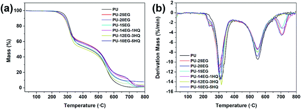
To further investigate the thermal stability of the PU/EG/HQ composites, the TGA/DTG curves under an air atmosphere are explored in Fig. 3 and the relevant results are shown in Table 5. Under an air atmosphere, the initial decomposition temperature T5% of all samples is much higher than that under a N2 atmosphere. The final char residue at 800 °C is lower in the presence of oxygen compared to that under N2 atmosphere. In the presence of EG, another degradation stage at 650–750 °C is observed in the PU/EG composites due to the further oxidative degradation of the unstable carbonaceous char. The char yield of the PU-15EG sample is 0.93 wt%, while the residue char of the PU-14EG-1HQ sample is 2.49 wt% when only 1 wt% HQ is added into the PU/EG system, which is attributed to the catalytic charring effect of HQ. The final char of the PU-10EG-5HQ samples gradually increased to 7.76 wt% with 5 wt% loading of HQ. These results indicate that the combination of EG and HQ can notably increase the char yield and enhance the high-temperature stability of the PU/EG/HQ samples.
| Samples | T5% (°C) | Tmax1 (°C) | Tmax2 (°C) | Tmax3 (°C) | CR at 800 °C (wt%) |
|---|---|---|---|---|---|
| a T5%: the temperature at 5 wt% weight loss (defined as the initial degradation temperature), Tmax1/Tmax2/Tmax3: the temperature at the first/second/third maximum weight loss rate, CR: the solid residual char yield. | |||||
| PU | 295.6 | 305.5 | 552.4 | — | 0.83 |
| PU-25EG | 280.7 | 299.9 | 548.4 | 711.4 | 2.11 |
| PU-20EG | 282.0 | 298.0 | 551.5 | 704.3 | 1.79 |
| PU-15EG | 283.1 | 300.1 | 550.7 | 703.4 | 0.93 |
| PU-14EG-1HQ | 282.8 | 304.6 | 551.4 | 712.2 | 2.49 |
| PU-12EG-3HQ | 281.4 | 316.3 | 551.7 | — | 3.86 |
| PU-10EG-5HQ | 287.8 | 314.6 | 550.7 | — | 7.76 |
3.3 Condensed-phase flame retardancy
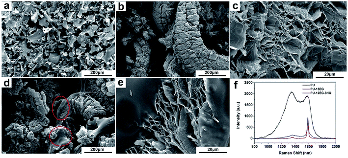
The char residues were evaluated to explore the specific mechanism of the enhanced flame retardancy of the PU/EG/HQ composites. As can be seen in Fig. 4, the cells of pure PU are severely broken with a lot of slag left on the cell surface. A “worm-like” intumescent char layer can be observed in the PU-15EG samples and a loose and porous sheet structure can be found in the “worm-like” char as shown in Fig. 4c. However, the as-obtained char layer possessing the “popcorn effect” lacks cohesion with the foam matrix, resulting in the char easily falling off from the foam surface, thereby losing the durability of its flame retardancy.23,24 Furthermore, a viscous liquid film covering the intumescent char surface can be seen in Fig. 4d (circled in red) and Fig. 4e as HQ is incorporated into the PU/EG systems. The main reason for this is that HQ can decompose to form phosphoric acid, metaphosphoric acid and polymetaphosphoric acid at high temperatures. These phosphorus oxyacids are non-volatile viscous semisolid materials which can cover the substrate surface to form a liquid film and can meanwhile catalyse the dehydration carbonization of foam.25 The formed viscous liquid film can reinforce the densification and strength of the “worm-like” intumescent char layer and enhance adhesion with the foam substrate at the same time.Raman spectra were investigated to detect the graphitic structure of the char residue for the PU/EG/HQ composites as shown in Fig. 4f. The G-band at 1580 cm−1 corresponds to the vibration of the sp2-bonds of the carbon atoms in graphite layers, while the D-band at 1350 cm−1 relates to the vibration of carbon atoms in disordered graphite or glass carbons.26–28 According to Fig. 4f, the PU-15EG and PU-12EG-3HQ samples exhibit a distinct Raman peak similar to that of pure EG with a sharply intense G-band and a low intensity D-band. Besides, the graphitization degree of the char residue is determined by the intensity ratio of the D and G bands (ID/IG).29 Therefore, the char residues of the PU-15EG and PU-12EG-3HQ samples have a higher graphitization degree than that of pure PU. This means that the intumescent char residue with a graphitized structure in the condensed phase can act as a physical barrier and effectively delay the volatilization of flammable products, further reducing oxygen and heat transfer into the combustion zone, leading to an enhancement of flame retardancy.
Based on the above discussion, the “worm-like” intumescent char layer of EG formed at high temperatures plays an essential role in the condensed-phase flame retardancy of polyurethane substrates. In order to comprehend the flame retardancy mechanism of EG in the condensed phase, PU and PU-15EG samples with the same size (30 × 30 × 30 mm3) were first dried in an oven at 70 °C for 10 h to remove excess moisture, and then all samples were put in a muffle furnace for 15 min at different temperatures varying from 100 °C to 600 °C. The correlative optical images of PU and PU-15EG samples at different temperatures are shown in Fig. 5. Both PU and PU-15EG samples began to shrink at 200 °C with a slightly darkened foam colour. When the temperature reached 300 °C, pure PU foam shrank and deformed heavily, while PU-15EG foam retained its original shape with a little swelling and a “worm-like” char emerged on the surface. When the temperature was increased to 400 °C, only a pile of residual char was left for the PU sample. However, the PU-15EG sample still maintained its shape, although some deformation occurred and more “worm-like” char appeared with the increased temperature from 400 °C to 600 °C.
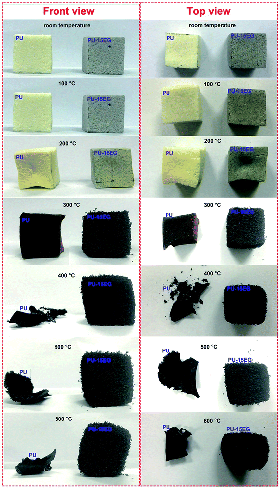 | ||
| Fig. 5 Optical photographs of the front and top views of PU and PU-15EG samples at different temperatures. | ||
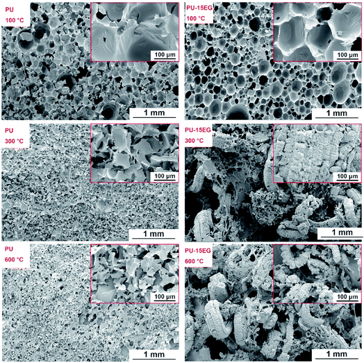
From the optical photographs in Fig. 5, it is obvious that 300 °C is a critical turning point for changes in samples’ appearance and shape. In order to intuitively observe microstructural changes in the char residues, SEM images of the PU and PU-15EG samples at different temperatures were taken, as shown in Fig. 6. The cells of the PU foam began to crack at 100 °C and a small amount of residue slag was left on the cell surface, while an intact cell structure can be observed in the PU-15EG sample with no char slag. With increased temperature, the cell rupture and cracking phenomena were more serious and a large amount of residue slag appeared on the surface of the PU foam. However, a “worm-like” intumescent char layer began to appear in the PU-15EG sample at 300 °C and more intumescent char can be observed with temperatures up to 600 °C, which could act as a stable barrier to effectively protect the substrate from further combustion. Optical photographs of the cross sections of the PU and PU-15EG samples are shown in Fig. 7. The intumescent char layer was also present in the cross section of the PU-15EG sample as the temperature rose. Therefore, the EG in polyurethane foam can form a stable intumescent char layer and affect the inhibition of heat transfer.
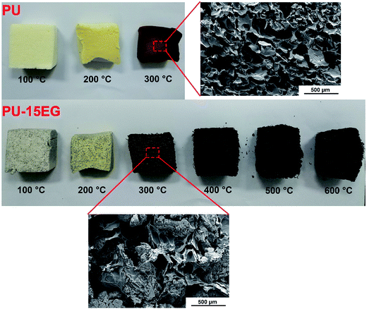 | ||
| Fig. 7 Optical photographs of the cross sections of PU and PU-15EG samples at different temperatures. | ||
3.4 Gas-phase flame retardancy
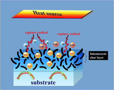
The three-dimensional TG-IR spectra of the evolved gases of the PU and PU-12EG-3HQ samples during thermal decomposition are shown in Fig. 8, with the purpose of investigating the flame-retardancy mechanism in the gas phase. As represented in Fig. 8a, the characteristic bands of pure PU during the pyrolysis process can be detected, such as those for hydrocarbons (3000–2850 cm−1), CO2 (2400–2300 cm−1), –NCO compounds (2300–2200 cm−1), carbonyl compounds (1800–1600 cm−1), NH3 (1000–900 cm−1), etc.30,31 The PU-12EG-3HQ samples release similar pyrolysis products to the PU samples, but it was found that the amount of flammable gases released from PU-12EG-3HQ samples is much less than that from PU. The absorbance intensity of the main volatilized products for the PU and PU-12EG-3HQ samples is illustrated in Fig. 9. The amount of toxic volatiles (–NCO, aromatic compounds and CO) and flammable gases (hydrocarbons, ethers and carbonyl compounds) released from the PU-12EG-3HQ samples is significantly decreased compared with that for pure PU, which is attributed to the formed stable char residues with a graphitic structure and the radical capture effect of HQ. HQ can release free radicals such as P˙ and PO˙ radicals at high temperatures which can capture OH˙ and H˙ radicals so that the combustion reaction is interrupted. Therefore, the use of a combination of EG and HQ can not only build a stable char barrier in the condensed phase to restrain mass and heat transfer, but also depress the amount of flammable gases released and catch free radicals in the gas phase.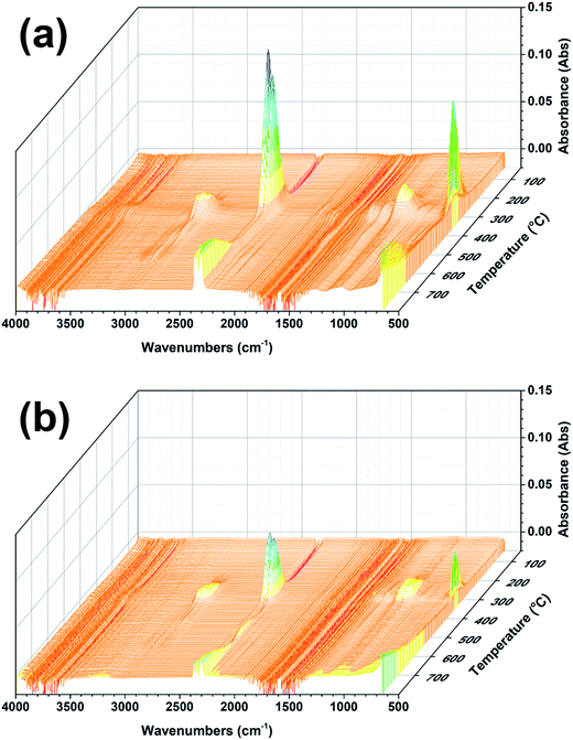 | ||
| Fig. 8 3D surface graphs for the TG-IR spectra of the evolved gases produced by (a) PU and (b) PU-12EG-3HQ samples. | ||
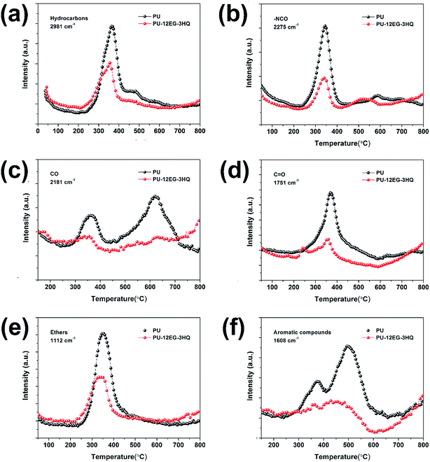 | ||
| Fig. 9 Absorbance of pyrolysis products for PU and PU-12EG-3HQ vs. temperature: (a) hydrocarbons, (b) –NCO compounds, (c) CO, (d) carbonyl compounds, (e) ethers and (f) aromatic compounds. | ||
3.5 Bi-phase flame-retardant mechanism
Based on the above description and discussion, a suggested bi-phase flame-retardancy mechanism is proposed in Fig. 10. Under the stimulation of an external heat source, EG gradually expands to form a “worm-like” intumescent char layer. The EG in the polyurethane foam can absorb a large amount of heat during the expansion process, and the formed stable char layer can further hinder mass/heat transfer and suppress the diffusion of flammable gas. Besides, the incorporation of HQ can decompose P˙ and PO˙ radicals under high temperature and terminate chain reactions in the gas phase by quenching OH˙ and H˙ radicals in the combustion zone. Thus, PU/EG/HQ composites achieve a reinforced fire-resistance property attributed to the gas–solid flame retardancy mechanism due to the combination of EG and HQ.4. Conclusions
In this work, PU/EG/HQ composites with highly effective flame retardancy were fabricated by the incorporation of two kinds of flame retardant, EG and HQ, during the synthesis of polyurethane. The as-synthesized PU/EG/HQ composites exhibit enhanced flame retardancy and thermal stability with the combination of EG and HQ. The composites achieve the UL-94 V-0 grade, a raised LOI value, an increased char yield at 800 °C and a PHRR value which is decreased by 58.5%. The formed viscous liquid film and the “worm-like” intumescent char layer with a graphitized structure play essential roles in the flame-retardancy enhancement of polyurethane foams in the condensed phase, acting as physical barriers and reducing oxygen and heat diffusion into the combustion zone. Moreover, the TG-IR test results illustrate that the amounts of toxic volatiles and flammable gases released from PU/EG/HQ samples are significantly decreased compared with those released from pure PU. The combination of EG and HQ can not only create a stable char residue in the condensed phase to restrain mass and heat transfer, but also decrease the amounts of flammable gases released and capture free radicals in the gas phase.Conflicts of interest
There are no conflicts to declare.Acknowledgements
This work was supported by the Natural Science Foundation of China (No. 51503067, 51573063 and 21174044), the Guangdong Natural Science Foundation (No. S2013020013855), the National Basic Research Development Program 973 in China (No. 2012CB025902), the Opening Fund of Key Laboratory of Building Fire Protection Engineering and Technology of MPS (No. KFKT2015MS01) and the Fundamental Research Funds for the Central Universities.References
- M. A. Garrido and R. Font, J. Anal. Appl. Pyrolysis, 2015, 113, 202–215 CrossRef CAS.
- A. König and E. Kroke, Polym. Adv. Technol., 2011, 22, 5–13 CrossRef.
- M. Thirumal, N. K. Singha, D. Khastgir, B. S. Manjunath and Y. P. Naik, J. Appl. Polym. Sci., 2010, 116, 2260–2268 CAS.
- B. Aydoğan and N. Usta, Res. Eng. Struct. Mat., 2017 DOI:10.17515/resm2016.63me0714.
- E. Ciecierska, M. Jurczyk-Kowalska, P. Bazarnik, M. Kowalski, S. Krauze and M. Lewandowska, J. Therm. Anal. Calorim., 2015, 123, 283–291 CrossRef.
- K. Salasinska, M. Borucka, M. Leszczyńska, W. Zatorski, M. Celiński and A. Gajek, et al., J. Therm. Anal. Calorim., 2017, 130, 131–141 CrossRef CAS.
- S. Duquesne, M. L. Bras, S. Bourbigot, R. Delobel, H. Vezin and G. Camino, et al., Fire Mater., 2003, 27, 103–117 CrossRef CAS.
- W. H. Awad and C. A. Wilkie, Polymer, 2010, 51, 2277–2285 CrossRef CAS.
- L. Wang, L. Zhang and M. Tian, Wear, 2012, 276–277, 85–93 CrossRef CAS.
- L. Liu, W. Li, W. Cui, X. Zhang and W. Ling, Pigm. Resin Technol., 2016, 45, 450–455 CrossRef CAS.
- W. Guo, B. Yu, Y. Yuan, L. Song and Y. Hu, Composites, Part B, 2017, 123, 154–164 CrossRef CAS.
- J. Li, Z. Li, H. Wang, Z. Wu, Z. Wang and S. Li, RSC Adv., 2016, 6, 91012–91023 RSC.
- M. Ciesielski, A. Schäfer and M. Döring, Polym. Adv. Technol., 2008, 19, 507–515 CrossRef CAS.
- E. Weil and S. Levchik, J. Fire Sci., 2016, 22, 25–40 CrossRef.
- A. Schäfer, S. Seibold, W. Lohstroh, O. Walter and M. Döring, J. Appl. Polym. Sci., 2007, 105, 685–696 CrossRef.
- M. Döring, M. Ciesielski and C. Heinzmann, ACS Symp., 2012, 1118, 295–309 CrossRef.
- T. Hoffmann, D. Pospiech, L. Häußler, K. Sahre, H. Komber, C. Harnisch, M. Auf Der Landwehr, A. Schäfer and M. Döring, High Perform. Polym., 2010, 22, 715–741 CrossRef CAS.
- E. Ciecierska, M. Jurczyk-Kowalska, P. Bazarnik, M. Gloc, M. Kulesza, M. Kowalski, S. Krauze and M. Lewandowska, Compos. Struct., 2016, 140, 67–76 CrossRef.
- T. Gupta and B. Adhikari, Thermochim. Acta, 2003, 402, 169–181 CrossRef CAS.
- İ. Kaya and A. Avcı, Mater. Chem. Phys., 2012, 133, 269–277 CrossRef.
- J. N. Gavgani, H. Adelnia and M. M. Gudarzi, J. Mater. Sci., 2013, 49, 243–254 CrossRef.
- M. Thirumal, D. Khastgir, N. K. Singha, B. S. Manjunath and Y. P. Naik, J. Appl. Polym. Sci., 2008, 110, 2586–2594 CrossRef CAS.
- J. Huang, Q. Tang, W. Liao, G. Wang, W. Wei and C. Li, Ind. Eng. Chem. Res., 2017, 56, 5253–5261 CrossRef CAS.
- S. Yang, J. Wang, S. Huo, M. Wang, J. Wang and B. Zhang, Polym. Degrad. Stab., 2016, 128, 89–98 CrossRef CAS.
- C. Peng, J. Li, Z. Wu, W. Peng and D. Zhou, RSC Adv., 2016, 6, 38300–38309 RSC.
- C. Guizani, K. Haddad, L. Limousy and M. Jeguirim, Carbon, 2017, 119, 519–521 CrossRef CAS.
- M. A. Pimenta, G. Dresselhaus, M. S. Dresselhaus, L. G. Cancado, A. Jorio and R. Saito, Phys. Chem. Chem. Phys., 2007, 9, 1276–1291 RSC.
- S. L. Rebelo, A. Guedes, M. E. Szefczyk, A. M. Pereira, J. P. Araujo and C. Freire, Phys. Chem. Chem. Phys., 2016, 18, 12784–12796 RSC.
- B. Yuan, Y. Hu, X. Chen, Y. Shi, Y. Niu, Y. Zhang, S. He and H. Dai, Composites, Part A, 2017, 100, 106–117 CrossRef CAS.
- H. Ding, C. Xia, J. Wang, C. Wang and F. Chu, J. Mater. Sci., 2016, 51, 5008–5018 CrossRef CAS.
- H. Ding, K. Huang, S. Li, L. Xu, J. Xia and M. Li, Polym. Test., 2017, 62, 325–334 CrossRef CAS.
| This journal is © The Royal Society of Chemistry 2018 |

