 Open Access Article
Structure improvements and numerical simulation of supersonic separators with diversion cone for separation and purification
Yingguang
Wang
 *ab and
Dapeng
Hu
a
aDepartment of Chemical Machinery, Dalian University of Technology, Dalian 116012, China. E-mail: wangyingguang7@126.com; Fax: +86 04277820120; Tel: +86 04277806753
bPetroChina Liaohe Petroleum Engineering Co., Ltd. (LPE), Panjin 124010, China
First published on 14th March 2018
Abstract
In the improved supersonic separator with the diversion cone, the reflow channel and the flush-type drain structure are adopted to overcome two shortcomings: the shock wave that easily appears in the diverging section of the nozzle and the swirling flow that occurs in subsonic conditions with poor efficiency, which makes the low-temperature section short and the cooling effect unsatisfactory. In this study, the distribution of the main parameters and the effects of the inlet temperature and outlet angle of the swirler were investigated by numerical simulation. The results indicated that the internal extension structure severely damaged the supersonic flow in the nozzle, while the flush type drainage port slightly influenced the fluid. The smaller outlet angle of the drainage port reduced its effect on the supersonic flow. Moreover, the improved device with the reflow enlarges the supersonic region and exhibits the better performance. In addition, it achieves a low temperature (221 K) and high centrifugal acceleration (2.2 × 10⁷ m s−2). Moreover, the inlet temperature of 300–320 K and the outlet angle of 50°–60° are recommended for the improved supersonic separator based on the comprehensive consideration of good expansion characteristics and centrifugal separation performance.
1 Introduction
The supersonic separator has the advantages of no rotating parts, high-pressure resistance, no external power drive, low-cost and reliable operation,1 which results in the strong applicability in the fields of natural gas dehydration, dehydrocarbon, and light hydrocarbon recovery.2 Though many examples of engineering applications have been reported,3 there are still some limitations on the efficiency of supersonic separation and operating flexibility.4The supersonic separator mainly includes three types: U-shape, front-swirl, and rear-swirl. Garrett et al.5–9 designed a series of the U-type supersonic separators, in which the diffuser of a converging-diverging nozzle was attached to a curved channel. Although Garrett et al. made numerous improvements in the supersonic separator, the structure was too complex and electromagnetic field or an inhibitor was needed to solve the problem of hydrate and frozen wall. Linhardt et al.10 and Nasikas et al.11 proposed a U-shaped separator adopting the principle of the centrifugal force and oblique shock wave or normal shock wave. However, the defect was the separation in the downstream of the shock wave, which resulted in the strong vortex and thus, it could not work under all Mach numbers. Haghighi et al.12,13 proposed a novel design for the U-shaped supersonic separators with a variable turning radius to maximize the centrifugal acceleration and the separation performance. However, the group did not specify the structural design such as settings of drainage hole and also, they did not consider the effects on the separation efficiency. In the front-swirl type, the guide blades are designed as the swirling device and located in the upstream of the nozzle entrance,14 which includes the circular15–19 and annular cross-sections within the inner body.20–25 However, the disadvantage is its large viscous loss and the swirling flow may damage the expansion effect. Moreover, the position of the shock wave keeps changing as the operation parameters constantly change, which results in the fact that the device cannot adapt to the change in the operating conditions, particularly under low-pressure conditions. In the rear-swirl type, the swirling device is installed after the nozzle exit.26,27 For the approach, the swirling flow is generated in supersonic velocity and the cross-section is circular, which causes some complex shock waves and the secondary evaporation of the droplets and increases the flow resistance. Thus far, the study of supersonic separator is mainly based on the abovementioned three types.
In addition, Eriqitai et al.28 introduced a dual-throat supersonic separation device with a porous wall that connected two sides of a so-called second throat in an attempt to improve the flow rate through the device. However, the exclusion of condensate was achieved by the circular structure between the inner and outer diameter casing. In the case of the massive quantities of the condensate, this circular gap would need to be increased, which would result in shock waves in the expansion section of the supersonic nozzle and influence the separation efficiency. Liu and Bao17 proposed a recycling supersonic separator, which has a recycling chamber between the straight section and the diffuser. In this system, the wet gas flowed into the straight section of the separator through the recirculation loop. The moisture that was not effectively separated went back and forth into the built-in swirl generator, thus improving the efficiency of the separation and dehydration.19,29,30 However, the evaporative source was once again introduced into the nozzle because of this structure. The liquid in the wet gas would occupy the circulation area of the nozzle and affect its working state, leading to instability. Moreover, Pouriya et al.31 generated the shock waves in the same position in the system as in the normal operation by controlling the back pressure. However, the method was only analyzed theoretically; in practice, the back pressure was determined by the system and adjusting the back pressure would affect the entire system. Therefore, the method of controlling the shock position may be applied poorly.
Since then, based on the simulations and experiments, many researchers have developed similar supersonic separators with the abovementioned designs to overcome the shortcomings of the present supersonic separator.32,33 Nevertheless, there is a lack of optimization research on the supersonic separator with a diversion cone, particularly with a drainage structure and a swirler. In this study, the design of the supersonic separator with the diversion cone was improved in terms of the structure of the reflow and drainage to enlarge the supersonic region in the device; also, the outlet angle of the swirler was optimized to improve the centrifugal separation performance. In addition, the influence of the inlet temperature and pressure recovery rate was investigated through numerical simulation.
2 The improved supersonic separator with a diversion cone
2.1 The overall structure of the supersonic separator
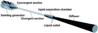
As shown in Fig. 1, the conventional supersonic separator was designed with a diversion cone and an axial-flow swirler in the entrance of the throat, which can weaken some complex shock waves and the flow resistance as compared to the swirling device designed as a delta wing and installed after the nozzle exit. In this structure, the strong swirl and supersonic speed result in low pressure along the centerline zone, which may cause the flow fluctuation and back-mixing. Therefore, the high-pressure gradient between the centerline zone and the wall zone severely affects the separation performance and increases the resistance loss. To improve the performance of the above structures, a reflow channel inside the cyclone and diversion cone was formed from the discharge chamber to the throat and diverging part as shown in the literature.34,35 The full length of the designed supersonic separator is 1560 mm, involving the swirling generator of 160 mm, the nozzle converging part of 100 mm, the diverging part of 500 mm, and the diffuser section of 800 mm. The diameters of the separator inlet and outlet are 116 mm and 27 mm, respectively. The diameters of the nozzle throat and the diffuser outlet are 24.16 mm and 120 mm, respectively. The cross area of the throat can be adjusted by changing the distance of the guide cone entering the throat. The diameter of the reflow channel is 19 mm.2.2 Three-dimensional axial-flow swirler and the discharge chamber
The axial-flow swirler is installed in the front part of the supersonic nozzle to generate swirl gas flow that provides centrifugal force. In this study, the molding principle of the guide vane adopts the method published in the literature.36 As shown in Fig. 1, the swirling generator is composed of 8 vanes and the height of the swirling generator is 160 mm and the exit angle of the vane is 55°. In the traditional structure of the discharge chamber, the internal extension type is used as it is beneficial to discharge the liquid directly into the drainage cavity; however, this structure severely damages the supersonic flow in the nozzle. Thus, the flush-type drain is utilized in the improved structure. The discharge clearance is 1.5 mm. The outer angle is 22° in the chamber as shown in Fig. 2.3 Calculation models
In this study, FLUENT software was employed to solve the governing equations with the finite volume method and the flow in the supersonic separator was assumed to be a steady flow. The medium of numerical simulation was air and its density was assumed to be similar to that of an ideal gas under the low-pressure conditions.3.1 Governing equations and turbulence model
The governing equations describing the flow in a supersonic separator involves the continuity, momentum, and energy equations; their general forms have been described in the literature.33It is particularly important to employ an appropriate turbulence model for the numerical calculation of the fluid flow in a supersonic separator, in which the anisotropic effect is significant due to the turbulence flow at a high speed with a strong swirl. In the current turbulence models, one of the greatest advantages is the Reynolds Stress Model that can accurately calculate the anisotropic effect. Therefore, we employed the Reynolds Stress Model37 to model the complex swirling flow in the supersonic separator. As the supersonic separation process was performed at low pressure in this study, the ideal gas model38 was employed to predict the gas dynamic parameters.
3.2 Numerical schemes and boundary conditions
In our numerical simulation, the velocity and pressure fields were coupled via the SIMPLE algorithm. According to the flow characteristics of the supersonic flow in the supersonic swirling separator, the pressure boundary conditions were assigned to the inlet (wet gas inlet) and the outlet of the nozzle (gas outlet and liquid outlet). The simulation was carried out with the pressure ratio Rnp = 1.5, the inlet pressure Pin = 0.15 MPa, and the inlet temperature Tin = 300 K. The non-slip and adiabatic boundary conditions were specified for the walls. The convergence criterion was set at 10−6 for the residual error of the energy equation and 10−3 for the residual error of other equations. The absolute error of the mass flow rate between the inlet and outlet was less than 10−4.3.3 Grid generation
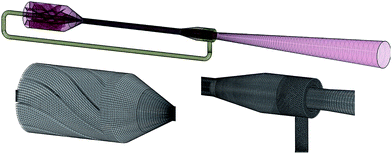
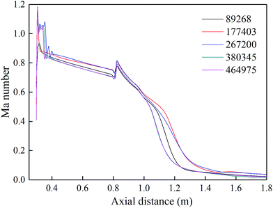
The mesh system is one of the major concerns for the numerical simulations. The structured and unstructured grids were employed for the supersonic separator to obtain the high-quality mesh in this study. The tetrahedral and hybrid elements were utilized for the spinning vane and discharge chamber area as a result of the complicated geometry and the hexahedral elements were performed for all of other parts of the supersonic separator as shown in Fig. 3.The mesh sensitivity test of the supersonic separator was carried out to obtain the mesh independent results. The Mach numbers along the nozzle axis center are described in Fig. 4, which indicates that 380345 and 464975 meshes were suitable to fine-capture the flow details in the supersonic separator. However, the grid density of about 464975 was chosen for our numerical calculations in order to make the calculation more precise.
3.4 Validation
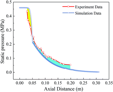
The model validation study was performed in a Laval nozzle according to the previous publication,39 including the detailed information about the operating and structural parameters of the experimental nozzle. The medium of numerical simulation was air. The comparisons of the pressure distribution are shown in Fig. 5. The simulation data was basically consistent with the experimental data in the range of 0–100 mm, but the certain observed deviation turns out to be above 100 mm, which mainly results from the wet air as the testing medium in the original experiment. The spontaneous condensation releases latent heat and causes the expansion process to deviate the constant entropy expansion. In the validation study, the simulation fluid was dry air and the condensation of wet air was not considered, which makes the condensation process decline along isentropic expansion line and the static pressure is below slightly the experiment data between 100 mm and 200 mm. Therefore, our computational approach can predict the supersonic flow very well.4 The flow field analysis in the supersonic separator
4.1 Effect of the drainage structure on the separation characteristics
Fig. 6 shows the distribution maps of the flow in the three different structural devices. It can be seen from the figure that the expansion section of the nozzle without the drain port is full of the supersonic flow and the static temperature is below 250 K (−23 °C). However, for the structure of the drainage interface, the drainage structure has a severe impact on the flow in the divergent section, which is due to the structural changes that disrupt the supersonic flow. The pressure in the outlet of the drainage cavity is higher than that in the outlet of the divergent section. When the dynamic pressure in the outlet of the divergent section cannot overcome the static pressure difference at the exit, the differential pressure will cause the reflux phenomenon of the drain cavity exit and affect the flow field characteristics in the nozzle. A comparative analysis of the two structures reveals that the internal flow-field in the flush drainage structure is significantly better than that in the internal extension-type drainage structure, but the flush-type drainage structure can cause some condensate droplets to be more easily discharged from the dry gas outlet. For the flush-type drainage structure, the Mach number in the expansion section of the Laval nozzle is within the range of 0.9–1.22 and the static temperature is within the range of 230–252 K, while for the internal extension type drainage structure, the Mach number is within the range of 0.7–1.11 and the static temperature is within the range of 240–274 K. Furthermore, the shock wave occurs in the diffuser with the internal extension type drainage structure and causes a greater total pressure loss.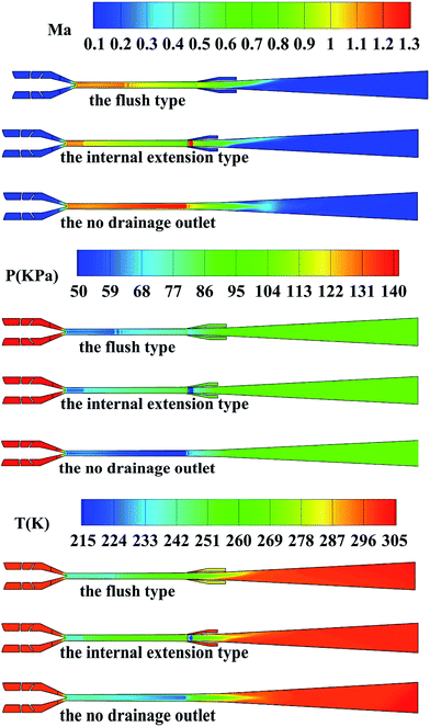 | ||
| Fig. 6 Distribution maps of the flow parameters in the supersonic gas separator for three different structures. | ||
The influence on the internal characteristics caused by the outer angle of drainage cavity is deeply investigated through simulation. It is evident from Fig. 7 that when the outlet angle changes from 22° to 42°, the supersonic area in the nozzle gradually reduces. The changing trend indicates that the smaller external inclination of the discharge cavity can weaken the effect of the drainage structure on the flow characteristics in the nozzle. There is no shock wave in the nozzle with the outlet angle of 22° of the drainage cavity. The flow condition remains supersonic within 0.379 m from the nozzle throat and the Mach number is 0.92 at the nozzle exit. When the outer angle is 42°, there is a weak shock wave at 0.067 m from the nozzle throat. In addition, the Mach number is reduced from 1.18 to 0.9, the static pressure rises from 65 kPa to 78 kPa, and the temperature increases from 237 K to 251 K.
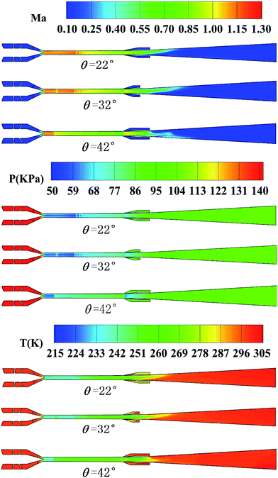 | ||
| Fig. 7 Distribution maps of the flow parameters in the supersonic gas separator with different outer angles of liquid drainage. | ||
4.2 Mach number and static temperature in the improved structure with the reflow
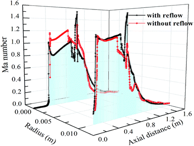
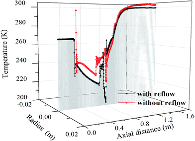
The flow field was simulated in the improved supersonic swirling separator with a reflow based on the abovementioned numerical methods. The Mach number and static temperature of the gas in the supersonic separator are presented in Fig. 8 and 9, respectively. The Mach number in the structure without the reflow is higher along the centerline section than that in the reflow structure, but it turns out just the opposite at the non-centerline section (see Fig. 8). For the reflow equipment, the velocity field remains stable and uniform in the entire cross-section. However, the Mach number lines of different sections exhibit intersecting phenomena in the non-reflow equipment, which shows that the fluid appears to be back-mixing.In addition, the position of the shock waves is 0.72 m and 0.643 m closer to the drain in the diverging section with and without the reflow, respectively. Thus, it can be seen that the differences between non-reflow and reflow structure result from the flow in reflow channel occupying the central low-pressure area, which indicated that the improved structure with reflow can eliminate back-mixing and improve the ability to resist flow fluctuation. Fig. 9 shows the low-temperature environment for the condensation obtained as a result of the gas expansion. It is at approximately 221 K and 231 K near the nozzle exit in the nozzle with and without the reflow, respectively. The result indicates that the improved supersonic separator makes the fluid swell even more in the nozzle and has a better refrigeration performance and the reflow channel.
4.3 Supersonic swirling flow in the improved structure
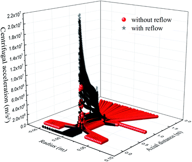
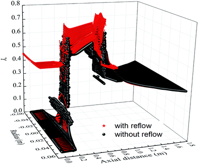
In a supersonic separator, as the gas flows through the diverging part of a Laval nozzle, it is accelerated to a supersonic speed, which leads to the low-temperature condition and causes water vapor or heavy hydrocarbons to condense into liquid droplets that can be separated under the impact of the centrifugal force. For this reason, it is particularly necessary to investigate the swirling characteristics of the gas flow in the diverging part of the improved separator.The distribution of the centrifugal acceleration is shown in Fig. 10. The highest centrifugal acceleration is 2.2 × 10⁷ m s−2 at the throat section with the reflow, which is 2.67 times higher than that without the reflow. Then, the centrifugal acceleration declines gradually in the divergent parts of the nozzle. Therefore, the swirl strength cannot simply be measured through the maximum centrifugal acceleration in the nozzle, but the attenuation extent of the centrifugal acceleration should also be considered. Furthermore, the centrifugal acceleration in the exit section of the nozzle should be employed to characterize the minimal value of the swirl strength. Fig. 10 depicts that the attenuation of centrifugal acceleration in the device without the reflow is faster than that in the improved device with the reflow. In addition, the centrifugal acceleration is 5.5 × 10⁶ m s−2 in the outlet of the nozzle with the reflow, which is 12-times higher than that without the reflow. Moreover, in the improved structure, the centrifugal acceleration retains the higher value (>2 × 10⁶ m s−2) in the expansion segment, leading to a better swirling effect on separation. However, in the original structure, the centrifugal acceleration will drop below 106 m s−2 after 0.41 m along the axial direction, which cannot guarantee sufficient centrifugal force for the droplet separation. This illustrates that the improved structure with the reflow contributes in improving the swirling characteristics to remove the condensed droplets.
4.4 Reflow propulsion in the improved device
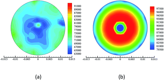
The fluid reaches the sound velocity at the throat in the supersonic separator, which is the premise of the reasonable design for the supersonic separator. Therefore, the flow field at the throat section is of high significance. Fig. 11 shows the pressure disturbance at the throat section in different structures. There are significant low-pressure zones in both structures. The visible back-mixing phenomenon appears in the conventional separator with the diversion cone. However, the improved structure with the reflow structure has distinct pressure levels and the low-pressure area is located in the center region of the nozzle. The design utilizes the low pressure near the throat of the Laval nozzle by the swirl and supersonic velocity and introduces flow from the discharge chamber to the throat and diverging part, which forms the reflow impetus.4.5 Effects on the pressure recovery rate caused by different structures
In general, the coefficient of pressure recovery rate is defined as follows: | (1) |
From the throat section to the outlet, the larger the coefficient of the pressure recovery rate, the greater is the expansion capacity of the Laval nozzle. However, in the diffuser, the smaller the coefficient of the pressure recovery rate, the faster is the pressure recovery. As shown in Fig. 12, the maximal value of the pressure recovery rate coefficient in the divergent section is 0.735 and 0.641 for the device with and without the reflow, respectively. The minimum value of the pressure recovery rate coefficient in the diffuser is 0.332 and 0.338 for the device with and without the reflow, respectively. It can be seen that as compared to the device without the reflow, the improved structure can expand more fully in the divergent section and speed-up the pressure recovery in the diffuser. Moreover, the coefficient of the pressure recovery rate also has a significant impact on the shock position. If the shock wave is located almost immovably in the supersonic zone of the nozzle, although the upstream flow can expand to the supersonic velocity, the downstream flow of the shock is subsonic, resulting in high temperature. As a result of the rapid rise in the temperature, the liquid particles condensed by the low temperature will re-evaporate into gas, which leads to the failure of the gas and liquid separation of this device. The position of the shock wave determines the separation performance of the supersonic separator and it could be affected by the pressure recovery rate coefficient. As illustrated in Fig. 12, for two different structures, when the coefficient of the pressure recovery rate is increased gradually from 0.641 to 0.735 in the divergent section, the shock wave moves into the nozzle outlet from 0.638 m to 0.734 m. This also proves that the improved structure with the reflow and the flush discharge chamber has better anti-shock ability.
4.6 Effects on the separator performance caused by the inlet temperature
Temperature is one of the important operating parameters affecting the performance of the supersonic separator. Therefore, it is necessary to investigate the influence of the temperature on the improved structure. As shown in Fig. 13, as the inlet temperature increases gradually from 300 K to 340 K, at the nozzle outlet, the maximum centrifugal acceleration increases gradually to about 2.65 × 10⁶ m s−2. The maximum Mach number alters slightly from 1.10 to 1.115. However, the minimum temperature varies considerably at the nozzle outlet from 230 K to 250 K. Within the 340–350 K range, the above parameters change remarkably, which is related to the increased interaction between the shock and boundary layer in the outlet of the nozzle. The interaction changes the entire flow-field structure.35 From the above changes, it can be seen that the inlet temperature has less influence on the centrifugal acceleration and the Mach number. However, the increase in the inlet temperature leads to the rapid growth in the minimum refrigeration temperature, which reduces the condensation rate of the droplets in the supersonic separator. In other words, an increase in inlet temperature leads to both positive and negative effects on the supersonic separator for the gas purification, but it does more harm than good. In addition, the abovementioned parameters can be sensitively affected by the inlet temperature when it increases from 300 K to 320 K, but their changes are not significant when the inlet temperature is between 320 K and 340 K. When the temperature reaches 350 K, the interaction between the shock waves and the boundary layer strengthens gradually in the outlet of the nozzle. In this case, the ideal centrifugal acceleration and Mach number may be achieved, but the expansion characteristic is significantly impaired. Therefore, based on the comprehensive consideration of good expansion characteristic and centrifugal separation performance, the inlet temperature ranging from 300 K to 320 K is recommended for the improved supersonic separator for different separation requirements. Moreover, the maximum centrifugal acceleration gradually declines from the throat section to the nozzle outlet. Moreover, as the inlet temperature increases, the attenuation increases slightly. Therefore, the separation performance of the supersonic separator cannot be measured by maximum acceleration, but should be considered on the whole.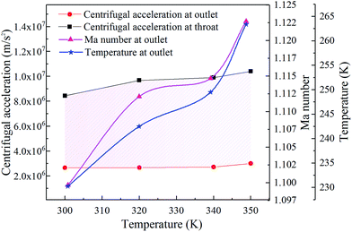 | ||
| Fig. 13 Distribution maps of the flow parameters in the improved structure at different temperatures. | ||
It is worth mentioning that in this paper, the simulation results of the changes in inlet temperature are slightly different from those reported in ref. 24. This proves that the inlet temperature has a weak effect on the temperature depressions. The reasons for these differences may be due to the structural differences and the interaction between the boundary layer and the shock waves.
4.7 Effects on the separator performance caused by the outlet angle of the swirler
From the design perspective of a swirling device, the outlet angle of the swirler is a key factor in generating a centrifugal force. The outlet angle of the swirler is defined as the acute angle between the outlet of the helical blade and the axial direction, which can be adjusted by installing it at the surface of the diversion cone as shown in Fig. 1. In this section, the numerical simulation was performed to optimize the outlet angle of the swirler for the gas purification. According to the theory of the gas dynamics and the abovementioned analysis, the variations in the static pressure and temperature are the dependent parameters when the gas expands in the supersonic nozzle. Therefore, the static temperature is used to evaluate the expansion characteristic of the improved supersonic separator, while the static pressure is not shown in the following analysis. The influence of different outlet angles on the swirling flow in the improved Laval nozzle was studied numerically by considering the angles of 30°, 40°, 50°, 55°, and 60°. Fig. 14 depicts the variations in the static temperature, Mach number, and centrifugal acceleration at the nozzle exit with different outlet angles of the static vane. The maximum centrifugal acceleration significantly decreases at the throat section with an increase in the outlet angles, in which the maximum centrifugal acceleration at the nozzle outlet does not change evidently. As the outlet angle increases, the gap in the centrifugal acceleration between the throat section and the nozzle outlet narrows, indicating that the centrifugal force decreases and is not conducive to the separation of the droplets on the wall. This indicates that a strong swirling flow can be generated in a small outlet angle to separate the condensed droplets from the gas–liquid mixtures. However, an increase in the outlet angle also results in the decline in the gas static temperature and Mach number at the nozzle outlet, which indicates that the low-temperature condition is strengthened although the centrifugal force is attenuating. In other words, the swirling characteristic and expansion effect are mutually exclusive. Therefore, we need to balance the swirling characteristic and expansion effect for improving the supersonic separator with the diversion cone and the axial-flow swirler. It can be seen from Fig. 14 that as the outlet angle ranges from 30° to 60°, the minimum static temperature at the nozzle exit can increase from 238 K to 229 K. Moreover, the maximum centrifugal acceleration is between 3.52 × 10⁶ m s−2 and 2.41 × 10⁶ m s−2 with the Mach number ranging from 1.01 Ma to 1.11 Ma. Nevertheless, when the outlet angle is between 50° and 60°, the changes of the abovementioned parameters are not significant. In particular, the change in temperature is only 1.88 K. Under this condition, both the expansion characteristic and the swirling flow are relatively reasonable for the gas purification. However, when the outlet angle of the swirler varies between 30° and 50°, the minimum static temperature varies from 239 K to 231 K although the maximum centrifugal acceleration can reach 3.52 × 10⁶ m s−2 with 1.01 Ma. In this case, the higher centrifugal separation performance may be achieved, but the expansion characteristic is significantly impaired as compared to the case when the outlet angle is between 50° and 60°. Therefore, based on the comprehensive consideration of good expansion characteristics and centrifugal separation performance, the outlet angle of 50°–60° is recommended for the improved supersonic separator.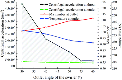 | ||
| Fig. 14 Distribution maps of the flow parameters in the improved structure at different outlet angles of the axial-flow swirler with the diversion cone. | ||
An interesting point here is that in this paper, via numerical simulation, the results of the simulation study on the outlet angle of the swirler are different from those in the published articles.4,40 These studies pointed out that the increase in the swirl angle can significantly increase the gas tangential velocity, which indicates that the swirling separation characteristic is greatly improved. However, this research draws the opposite conclusion. A reason for this difference might be due to the differences in the structure of the swirler and the supersonic separator.
5 Conclusions
The ordinary supersonic separator was improved in terms of reflow channel and the discharge chamber. The flow characteristics of air were studied through numerical simulations and the data were compared with that obtained for the separator without the reflow. Moreover, the influence of the inlet temperature, pressure recovery rate, and outlet angle of the swirler on the improved equipment was investigated. The main conclusions are summarized as follows.Under the same conditions (i.e., Rnp = 1.5, Pin = 0.15 MPa, and Tin = 300 K), two types of drainage structures are proposed: the flush type and the internal extension type. The inner extension-type structure severely damages the supersonic flow in the nozzle. However, the flush-type structure has less influence on the flow condition in the nozzle and the static temperature is below 250 K in the expansion section. For the flush type structure, the smaller obliquity of the discharge cavity can reduce the effect of drainage port on the supersonic flow.
Another improvement is introducing the reflow channel into the supersonic separator between the drain chamber and the throat. The improved structure can achieve a low temperature of 221 K and high centrifugal acceleration of 2.2 × 10⁷ m s−2, which proves that the supersonic separator with the reflow has a good cooling and separation performance. Moreover, in the separator with the reflow, the shock wave occurs at the distance of 0.72 m of the outlet of the nozzle and it has a better ability to resist flow fluctuation and back-mixing.
By introducing the coefficient of pressure recovery rate, this article discusses the pressure recovery rate and expansion capacity for the improved structure. The improved structure can expand more fully in the divergent section and speed-up the pressure recovery in the diffuser. Moreover, the inlet temperature has a weak influence on the centrifugal acceleration and Mach number at the nozzle outlet, while it has great influence on the minimum cooling temperature in the improved device. The swirling flow is improved in the diverging section, benefiting from the decrease in the outlet angle of the swirler. However, the expansion characteristic and centrifugal separation performance are opposing for the improved separator. The outlet angle of the swirler was optimized by considering the above balance.
In the future, we are planning to carry out the experimental study on the improved structure in order to verify the accuracy of the simulation and enhance the separation performance. We are also investigating other factors affecting the separation performance to understand in more depth the flow dynamics in the improved structure.
Conflicts of interest
There are no conflicts to declare.Acknowledgements
This study is supported by the National Natural Science Foundation of China (No. 21206013 and No. 21476036) and Basic research project of Key Laboratory of Liaoning Provincial Education Department (No. LZ2015019).References
- J. M. Brouwer and H. D. Epsom, This paper was prepared for presentation at Offshore Europe 2003 held in Aberdeen, UK, 2–5, September 2003, SPE 83977.
- P. B. Machado, J. G. M. Monteiro, J. L. Medeiros, H. D. Epsom and O. Q. F. Araujo, J. Nat. Gas Sci. Eng., 2012, 6, 43–49, DOI:10.1016/j.jngse.2012.03.001.
- M. Betting and H. Epsom, World Oil, 2007, 197–200 Search PubMed.
- C. Wen, A. Li, J. H. Walther and Y. Yang, Sep. Purif. Technol., 2016, 168, 68–73, DOI:10.1016/j.seppur.2016.05.019.
- R. L. Garrett, W. K. Oehlschlager and J. F. Tomich, J. Eng. Ind., 1968, 90, 609–612 CrossRef CAS.
- R. L. Garrett, US Pat., 3528217, 15, September, 1970.
- R. L. Garrett and W. J. Mcdomald, US Pat., 3528218, 15, September, 1970.
- R. L. Garrett and W. J. Mcdomald, US Pat., 3528221, 15, September, 1970.
- R. L. Garrett, US Pat., 3559373, 2, February, 1971.
- H. D. Linhardt and J. H. Beveridge, US Pat., 4292050, 29, September, 1981.
- A. Nasikas, US Pat., 5306330, 26, April, 1994.
- M. Haghighi, M. dissertation, Memorial university of Newfoundland, Canada, 2010.
- M. Haghighi, K. A. Hawboldt and M. A. Abdi, in, 2013 Offshore Technology Conference, Houston, Texas, U.S.A, OTC 23974, 6–9, May, 2013 Search PubMed.
- P. Schinkelshoek and H. Epsom, in, 2006 Offshore Technology Conference, Houston, Texas, USA, OTC-17884-PP, 1–4, May, 2006 Search PubMed.
- K. Y. Gu, Z. L. Liu and H. W. Liu, CN Patent, 200410074338.8, 17, May, 2006.
- X. W. Liu, D. dissertation, Beijing University of Technology, China, 2005.
- Z. L. Liu and L. L. Bao, CN Patent, 200920223127.4, 28, July, 2010.
- Z. H. Wang, C. Zhu, X. Q. Wang and X. D. Dan, Chem. Eng. Oil Gas, 2014, 43, 117–121 CrossRef.
- Y. Kang, CN Patent, 201110047056.9, 28, September, 2011.
- H. Z. Pang, M. dissertation, Beijing University of Technology, China, 2009.
- Z. L. Liu, H. Z. Pang, W. M. Jiang, J. F. Sun and L. L. Bao, CN Patent, 200810224499.9, 11, March, 2009.
- C. Wen, W. X. Cao, Y. Yang and W. M. Jiang, CN Patent, 201120048496.1, 16, November, 2011.
- Q. F. Ma, D. dissertation, Dalian University of Technology, China, 2009.
- X. W. Cao and W. Yang, J. Nat. Gas Sci. Eng., 2015, 27, 1667–1676, DOI:10.1016/j.jngse.2015.10.029.
- B. F. Bai and C. Chang, CN Patent, 200910024347.9, 5, May, 2009.
- V. Alfyorov, L. Bagirov, L. Dmitriev, V. Feygin, S. Imayev and J. R. Lacey, Oil Gas J., 2005, 103, 53–58 CAS.
- V. I. Alferov, et al., US Pat., 6372019, 16, April, 2002.
- Eriqitai, J. Han, R. Duan and M. Wu, Chin. J. Chem. Eng., 2014, 22, 370–382, DOI:10.1016/S1004-9541(14)60065-3.
- L. L. Bao, Z. L. Liu and J. Liu, Sci. Technol.: Eng., 2017, 17, 177–180 Search PubMed.
- N. Q. Chen, M. dissertation, Xi'an Shiyou University, China, 2014.
- P. H. Niknam, H. R. Mortaheb and B. Mokhtarani, J. Nat. Gas Sci. Eng., 2017, 43, 90–95, DOI:10.1016/j.jngse.2017.03.017.
- M. Haghighi, K. A. Hawboldt and M. A. Abdi, J. Nat. Gas Sci. Eng., 2015, 27, 109–121, DOI:10.1016/j.jngse.2015.08.049.
- Y. Yang and C. Wen, Sep. Purif. Technol., 2017, 174, 22–28, DOI:10.1016/j.seppur.2016.10.002.
- D. P. Hu, Y. G. Wang, Y. Yu, P. Q. Liu, W. W. Ren and C. Zhu, CN Patent, 107234010A, 10, October, 2010.
- D. P. Hu, Y. G. Wang and C. Ma, Chem. Eng. Process., 2018, 124, 109–121, DOI:10.1016/j.cep.2017.12.004.
- Y. M. Jin, C. Fan, Y. Mao and M. X. Shi, Chem. Eng. Mach., 1999, 26, 21–24 Search PubMed.
- ANSYS Fluent User Manual, Ansys Inc., 2014 Search PubMed.
- Y. Yang, C. Wen, S. L. Wang and Y. Q. Feng, J. Nat. Gas Sci. Eng., 2014, 21, 829–836, DOI:10.1016/j.jngse.2014.10.010.
- W. M. Jiang, Z. L. Liu and X. L. Liu, et al. , CIESC J., 2011, 62, 97–102 CAS.
- Y. Yan, A. Q. Li and C. Wen, Fuel Process. Technol., 2017, 156, 265–270, DOI:10.1016/j.fuproc.2016.09.006.
| This journal is © The Royal Society of Chemistry 2018 |

