 Open Access Article
Creative Commons Attribution 3.0 Unported Licence
Nitrogen and phosphorus co-doped carbon modified activated carbon as an efficient oxygen reduction catalyst for microbial fuel cells†
Kang Lv,
Hua Zhang and
Shuiliang Chen *
*
Department of Chemistry and Chemical Engineering, Jiangxi Normal University, Nanchang, 330022, China. E-mail: slchenjxnu@jxnu.edu.cn; Fax: +86 791 8120740; Tel: +86 791 8120536
First published on 3rd January 2018
Abstract
Activated carbon (AC) is an environmentally sustainable oxygen reduction reaction (ORR) catalyst and widely used in MFCs due to its intrinsic high specific surface area and mesoporous characteristics, but it shows relatively high ORR over-potential thus low electrocatalytic activity. In this study, a method of doped carbon modification was employed to decrease the over-potential and improve the ORR electrocatalytic activity of the AC catalyst. Nitrogen and phosphorus co-doped carbon modified AC (NPC@AC) was prepared by coating phytic acid doped polyaniline onto AC through in situ oxidative polymerization and subsequent high-temperature pyrolysis. The as-prepared NPC@AC possessed a large surface area of ∼649.3 m2 g−1 inherited from AC and a low ORR over-potential with a highly positive onset potential of +0.22 V vs. Ag/AgCl from NPC, thus showing an enhanced ORR electrocatalytic activity in neutral solution compared to the pristine AC, and even better than the pure NPC. The air-cathode MFC using the NPC@AC catalyst generated a much higher open circuit voltage of 0.753 V and two times higher power density of 1223 mW m−2 than that using the pristine AC catalyst of about 0.432 V and 595 mW m−2, respectively.
1. Introduction
Thanks to the dual-function of electricity generation and waste removal, microbial fuel cells (MFCs) have been targeted as a promising technology for the applications of renewable bioenergy, wastewater treatment, bio-sensing and bioremediation.1–3 The cathode is a crucial component of an MFC that determines its cost and performance. Notwithstanding, the oxygen reduction reaction (ORR) is the most important cathodic reaction in fuel cell technology (including MFCs) for power generation due to its high biochemical standard potential (+0.82 V vs. SHE) and its abundant availability from air. The most feasible cathode configuration for large-scale application of MFCs is the air-cathode because its use solves the issue of limited oxygen solubility in water and makes purging obsolete. The non-limiting availability of oxygen at air cathodes, ultimately, makes it possible to achieve higher current densities.4–6 Unfortunately, the sluggish ORR kinetics demands the use of efficient electrocatalysts. Pt-based catalysts are firstly used as the ORR catalyst in lab-scale MFC reactors.7 However, their high cost and poor stability hampering their use in practical applications of MFCs.8,9 Various alternative ORR catalysts to Pt have been proposed, including transition metal complexes,10,11 non-noble metal oxides,12–15 nitrogen-doped carbon nanotubes16 and graphene,17 and so on. Although these alternatives have been proved to be high efficient ORR catalysts for MFCs, the disadvantages, such as high manufacturing cost and complex fabrication procedure, hinder their practical application.Activated carbon (AC) is a low-cost carbon material with large surface area (>500 m2 g−1) and has been widely used for adsorption, purification, catalyst and catalyst carrier.18,19 AC is also a cost-effective ORR catalyst for the air-cathode of MFCs.20–24 It has been reported that air-cathode using AC as ORR catalyst generated relatively higher power densities and showed better long-term durability than that using Pt/C catalyst. However, the electrocatalytic activity of the pristine AC toward ORR is unsatisfactory due to its high ORR over-potential. Direct doping of nitrogen is an effective strategy to improve the electrocatalytic activity of the AC for ORR.25–28 However, the improvement on the electrocatalytic activity of the AC is limited because a relatively low content of nitrogen (typically below 2%) can be incorporated to the AC. To further increase the content of N doping in the AC, Fe–N co-doped carbon had been incorporated to the AC and led to great increase of electrocatalytic performance of AC for ORR.29,30
It had been reported that introduction of a second heteroatom, such as B, S or P, to the N-doped carbon nanomaterials, was able to modulate the electronic and surface polarities, thus further increase the ORR catalyst activity of the carbon nanomaterial.31–34 At this point, those prior findings inspire us to explore a proper method on incorporated co-doped carbon to the AC to improve its ORR electrocatalytic activity. In this study, N and P co-doped carbon was incorporated to the AC (denoted as NPC@AC) by coating phytic acid doped polyaniline through in situ oxidative polymerization and subsequent high-temperature pyrolysis. The NPC@AC combined the good characteristics of high specific surface area of the AC and low ORR over-potential of the NPC, thus enhanced ORR electrocatalytic activity in neutral solutions comparing to the pure AC and NPC. MFC using the NPC@AC catalyst generated two times higher power density than that using the pristine AC catalyst.
2. Experimental
2.1 Preparation of NPC@AC
NPC@AC was prepared by a two-step process including phytic acid (PA) doped polyaniline coating and subsequent high-temperature pyrolysis. The coating of PA doped polyaniline onto AC was realized by in situ oxidative polymerization polyaniline in the presence of PA. In a typical procedure, 0.0625 mol ammonium persulfate was dissolved in 50 mL deionized water under stirring to prepare solution A. Solution B was prepared by mixing 50 mmol PA, 250 mmol aniline monomers in 100 mL of deionized water. Various amount of AC was dispersed in solution B. After both solutions being cooled down to 4 °C, solution A was poured into B and mixed swiftly by mechanical stirring, and kept under 4 °C for 8 hours without stirring. After washing with deionized water for three times to remove the excess acid and salts, the resultant PA doped carbon coated AC composite was dried and subsequently put into a tube furnace for pyrolysis. The pyrolysis process was conducted by heating to 950 °C with a temperature ramp of 5 °C min−1 in argon and annealing for 2 h at the final temperature. After naturally cooling to below 200 °C, the NPC@AC samples with NPC/AC ratio of 0.25, 0.4, 0.7 and 1.7 were obtained. These samples were denoted as NPC@AC-x, x represents the NPC/AC ratio. For comparison, the N mono-doped carbon and P mono-doped carbon modified AC were also prepared, and denoted as NC@AC and PC@AC, respectively. The NC@AC and PC@AC were prepared using the same procedures and same amount of reactants as that of the NPC@AC-0.7 sample, but using hydrochloric acid to replace the phytic acid when preparing NC@AC, and do not using aniline when preparing PC@AC.2.2 Characterization and electrochemical test
The morphological characterization of the AC catalysts was conducted by using scanning electron microscope (SEM, Vega3, TESCAN) and transmission electron microscope (TEM, JEM-2100, JEOL). X-ray photoelectron spectroscopy (XPS, PHI Quantera SXM™) was introduced to exam the elemental composition and chemical state of samples. The crystalline structure was analyzed with powder X-ray diffraction (XRD, X'Pert-PRO) with a Cu K(alpha) target radiation source (λ = 0.154056 nm). The Raman spectra were recorded on a LabRAM Aramis (Horiba Jobin Yvon S.A.S) with a 633 nm wavelength laser.All electrochemical measurements were conducted at a three-electrode system with 50 mM phosphate buffer solution (PBS, pH = 7.0) as electrolyte. Ag/AgCl (25 °C, saturated KCl internal solution) and Pt foil electrode were used as the reference and counter electrode, respectively. For cyclic voltammetry (CV) test, the catalysts were loaded onto a common glass carbon (Φ = 3 mm) and used as the working electrode. 1 mg catalyst was dispersed in a mixture solution containing 250 μL deionized water and 25 μL of 5 wt% Nafion® dispersion under sonication and formed a catalyst ink; then, 5 μL catalyst ink was pipetted onto a mirror-polished glassy carbon electrode and naturally dried up. For linear scanning voltammetry (LSV) tests, rotating disk electrode (RDE, Φ = 5 mm) and rotating ring-disk electrode (RRDE, Φ = 5 mm) were used. 15 μL catalyst ink was used for both RDE and RRDE. The LSV tests were conducted on the bi-potentiostat (Bio-logic, VMP3) equipped with a speed controller (AFMSRCE, Pine Instrument Co., USA). The electron transfer numbers (n) of catalysts were calculated according to the following equation:
2.3 MFCs construction and operation
Single-chamber cubic air-cathode MFC set-up was used to measure the catalytic performance of the AC-based ORR catalysts in the MFC. The air-cathodes were fabricated by rolling method according to previous reports,28,35 using polyfluortetraethylene (PTFE) as binder and stainless steel mesh as current collector. The mass ratio of catalyst/PTFE was controlled to be about 4/1 and the loading of catalyst was controlled to be about 20 mg cm−2. Graphite fiber brushes (Jilin Chemical Fiber Group Co., Ltd., China) heat-treated at 450 °C for 30 min were used as anodes. A resistor with resistance of 1000 Ω was loaded between the brush anode and air-cathode. All MFCs were inoculated with effluent from another MFC, which was initially inoculated with wastewater from local wastewater treatment plant and operated for over 6 months. To keep the metabolism of bacteria, each reactor was fed with a medium containing acetate (1 g L−1), vitamin solution (12.5 mL L−1), trace element solution (12.5 mL L−1) in 50 mM phosphate buffer solution (PBS: pH 7.0, 10.9233 g L−1 Na2HPO4·12H2O, 3.042 g L−1 NaH2PO4·2H2O, 0.31 g L−1 NH4Cl, 0.13 g L−1 KCl). The medium was refreshed as soon as the voltage dropped below 100 mV. The cell voltage was monitored every minute by a date collection system (HIOKI LR8431-30). Polarization and power density curves were obtained by varying external circuit resistance with each resistor used for a full batch cycle. The power density and current density were normalized to the projected area of the air-cathode (7 cm2). Each measurement was repeated for at least three times.3. Results and discussion
3.1 Electrocatalytic activity of NPC@AC with different NPC/AC ratio
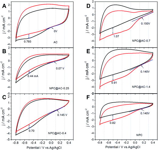
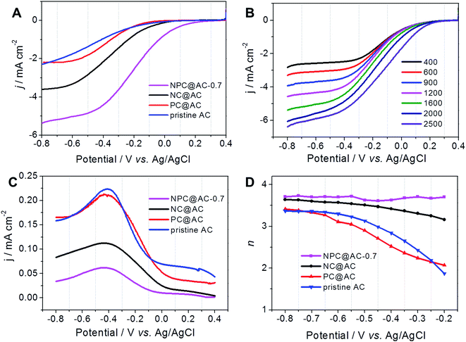
The NPC@AC samples were fabricated by a two-step process including in situ oxidative polymerization and high-temperature pyrolysis. Here, aniline and PA were used as the nitrogen and phosphorus sources, respectively. In order to investigate the effect of NPC/AC ratio on the ORR electrocatalytic activity of the NPC@AC, cyclic voltammograms were performed in neutral media. As shown in Fig. 1, the NPC modification could bring great increase of ORR onset potential to the AC-based catalysts. The ORR onset potential of NPC@AC positively shift from 0 V of the pristine AC to +0.15 V of the NPC@AC-0.7, is kept at about +0.14 V with further increase the NPC content. Moreover, the NPC modification also leads to increase in the ORR current density. The NPC@AC-0.7 delivers a current density of 1.07 mA cm−2, which is 30% higher ORR current density than that of the pristine AC and even the pure NPC. In view of the best ORR electrocatalytic performance in terms of the more positive ORR onset potential and current density, thus the NPC@AC-0.7 were selected for further electrochemical performance investigation and compared to the single N doped (NC@AC) and P doped (PC@AC) carbon modified AC.RDE voltammograms were performed in O2-saturated 50 mM PBS and the results are shown in Fig. 2A. After doped carbon modification, the onset potential of the AC-based catalysts show a great positive shift from 0 V (pristine AC) to +0.22 V (NPC@AC-0.7), the ORR current densities also great increase, which is well in accordance to the CV results discussed in the preceding paragraph. Moreover, the ORR electrocatalytic activity of the NPC@AC-0.7 modified by co-doped carbon outperforms that of the NC@AC and PC@AC modified by mono-doped carbon. Furthermore, the RDE voltammograms of the NPC@AC-0.7 display a nearly one-step process of ORR at different rotating speeds (Fig. 2B), implying a four-electron ORR pathway. Moreover, RRDE measurements were conducted to study the generation of hydrogen peroxide for different catalysts (Fig. 2C). As expected, the NPC@AC-0.7 shows lower hydrogen peroxide generation than that of other catalysts. The average electron transfer numbers (n) of the NPC@AC-0.7 catalyst based on the RRDE measurements is about 3.6 (Fig. 2D). As can be seen, the NPC@AC-0.7 possesses excellent electrocatalytic activity for ORR in terms of positive ORR onset potential and high disc current, highlighting the importance of the N, P co-doping and mesoporous structure for ORR.
3.2 Morphological and elemental characterization
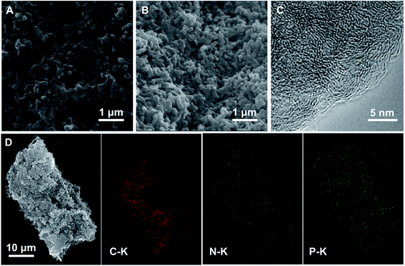
SEM morphological analyses demonstrate that the NPC@AC-0.7 exhibits a nanorod network surface (Fig. 3A and B) inherited from the PA doped PANi@AC. High-resolution transmission microscope (HR-TEM) image in Fig. 3C reveals that the NPC@AC-0.7 sample exhibits an edge-like graphitic carbon structure, which might be derived from of the NPC. To further detect the possible crystalline structure in the NPC@AC-0.7, XRD and Raman analyses were performed and the corresponding results are presented in Fig. S1.† XRD patterns in Fig. S1A† show that the pristine AC only has a board peak at around 23° corresponding to the (002) of the carbon. A new broad peak at around 43° corresponding to the (100) appears after incorporation of doped carbons, indicating the existence of graphitic carbon structure. Moreover, the intensity of the (100) NPC@AC-0.7 is stronger than that in the mono-doped carbon, NC@AC and PC@AC, demonstrating a higher average graphitization degree. This tendency could also be confirmed by the Raman analysis results. As shown in Fig. S1B,† the Raman spectra of the AC-based catalysts all display two wide peaks at ∼1327 cm−1 (D-band) and ∼1594 cm−1 (G-band). The intensity ratios of D band to G band (ID/IG) which reflects the average graphitization degree of different catalysts are calculated and summarized in Table 1. After doped carbon modification, the ID/IG value of the AC-based catalysts decreased, demonstrating increase in the average graphitization degree. Moreover, the N and P co-doped NPC@AC-0.7 show lower ID/IG value than mono-doped NC@AC and PC@AC, thus confirms the higher average graphitization degree in the NPC@AC-0.7, indicating the positive effect of phosphorus doping on the graphitization of the carbon layers.36| Samples | SBET (m2 g−1) | Vpore (cm3 g−1) | ID/IG | Elemental analysis (at%) | |||
|---|---|---|---|---|---|---|---|
| C | N | O | P | ||||
| NPC@AC-0.7 | 649.2 | 0.656 | 1.26 | 86.87 | 4.54 | 6.37 | 2.21 |
| NC@AC | 500.6 | 0.514 | 1.42 | 92.61 | 4.60 | 2.80 | — |
| PC@AC | 456.0 | 0.364 | 1.52 | 88.29 | 0.55 | 7.57 | 3.59 |
| Pristine AC | 943.5 | 0.919 | 1.64 | 92.53 | 1.22 | 6.24 | — |
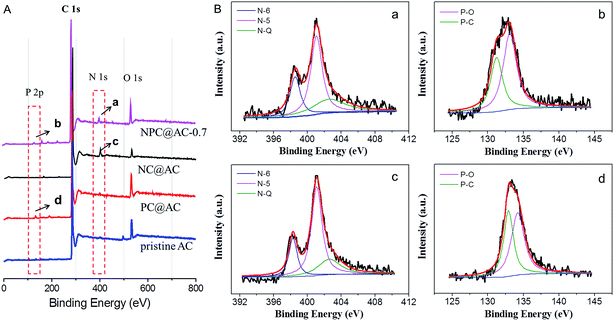
To confirm the incorporation of heteroatom (N and/or P) doped carbons to the AC, XPS analysis was conducted and the spectra are shown in Fig. 4A, and the textural parameters are summarized in Table 1. As expected, the XPS spectrum of confirms the presence of the O, N, and P heteroatom in the NPC@AC-0.7 with N and P content of 4.54% and 2.21%, respectively. The fine N 1s spectra of the NPC@AC-0.7 (Fig. 4Ba) and NC@AC (Fig. 4Bc) can be fitted into three bands at ∼398.6, 401.3 and 402.5 eV, which correspond to pyridinic (N-6), pyrrolic (N-5) nitrogen and pyridine-N-oxide groups (N-Q), respectively.37–39 The incorporation of N atom to carbon ring could change the spin density and atomic charge distribution of carbon atoms in the graphitic layers, which effectively weakened the O–O bonding energy, thus facilitated ORR catalytic activity.40,41 The fine P 2p spectra of the NPC@AC (Fig. 4Bb) and PC@AC (Fig. 4Bd) can be fitted into two bands at ∼131.8 and 133.6 eV, which were ascribed to P–C and P–O states, respectively. It was reported that P-doping could enhance the charge delocalization of the carbon atoms and produce carbon structures with many edge sites.42 These electrical and physical alternations of carbon substrate caused by N, P co-doping would be more favorable for the reduction of the oxygen on the carbon surface, thus probably give rise to high ORR catalytic activity.
N2 adsorption–desorption isotherm curves (Fig. S2A†) show that the NPC@AC-0.7 preserve a high specific surface area of 649.2 m2 g−1 and a total pore volume of 0.656 cm3 g−1 (Table 1), which is about 70% specific surface area and pore volume of the pristine AC (943.5 m2 g−1 and 0.919 cm3 g−1). The relatively lower specific surface area the NPC@AC-0.7 is likely due to the occupancy of partial pores of the AC by the deposition of NPC during pyrolysis process. Barrett–Joyner–Halenda (BJH) pore size distribution curves of the as-prepared catalysts (Fig. S2B†) confirm the presence of mesopores with diameters <10 nm, which would be in favor for electrocatalytic applications.
3.3 Performance of the electrocatalyst in the air-cathode of MFCs
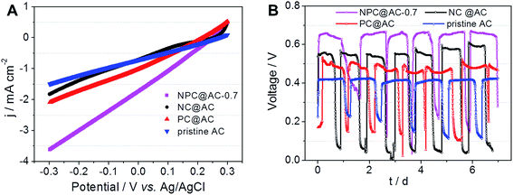
The practical performance of different catalysts in MFCs, air-cathodes with various ORR catalysts were prepared by rolling method as reported previously.28,35 The LSV curves in Fig. 5A demonstrate that all the air-cathodes with doped carbon modified AC catalysts exhibit higher current response than that of pristine AC catalyst. Comparing to the NC@AC and PC@AC, the NPC@AC-0.7 displays the highest current density. As shown in Fig. 5B, air-cathode MFC using NPC@AC-0.7 ORR catalyst is able to generate a stable voltage of 0.668 V across an external resistor of 1000 Ω, which is much higher than that of using the NC@AC (0.583 V), PC@AC (0.517 V) and pristine AC (0.432 V) catalysts, respectively. These results imply that modification by doped carbon is an effective method to enhance the ORR activity of the AC. Moreover, the NPC@AC-0.7 prepared by N and P co-doped carbon modification outperforms the NC@AC and PC@AC by mono-doped carbon modification, when using as ORR catalyst in the air-cathode of MFC.As shown in Fig. 6A, using the NPC@AC-0.7 catalyst, the air-cathode MFC is able to generate a higher open circuit voltage (OCV) of 0.753 V than that of using other catalysts. Moreover, the electrode polarization curves in Fig. 6B show that the increase of OCV is mainly brought by the improvement of performance at the air-cathode. These results demonstrate that incorporation of NPC to the AC greatly reduce the over-potential of air-cathode towards ORR, thus lead to high OCV. The power density curves of air-cathode MFC using different catalysts in Fig. 6A reveal that the air-cathode MFC using the NPC@AC-0.7 ORR catalyst shows better performance than the mono-doped carbon modified AC, NC@AC and PC@AC, and the pristine AC. And the power densities arranged in this order: pristine AC (595 mW m−2) < PC@AC (762 mW m−2) < NC@AC (895 mW m−2) < NPC@AC-0.7 (1223 mW m−2). The power density from the MFC with NPC@AC-0.7 catalyst (1223 mW m−2) is two times higher than that with pristine AC. These results demonstrate that the NPC@AC-0.7 is an efficient ORR catalyst for air-cathode of MFCs.
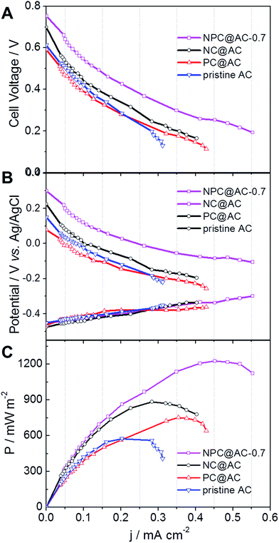 | ||
| Fig. 6 (A) Cell and (B) electrode polarization and (C) power density curves of air-cathode MFCs using different AC based catalysts. | ||
4. Conclusions
The method of doped carbon modification was employed to improve the ORR electrocatalytic activity of the AC electrocatalyst. The doped carbon modification were realized by using a facilely and scalable process including steps of coating of PA doped polyaniline by in situ oxidative polymerization and subsequent high-temperature pyrolysis. The NPC@AC-0.7 modified by N and P co-doped carbon, inherited the large surface area and mesoporous characteristics from the AC and had improved degree of graphitization, thus exhibited higher ORR electrocatalytic activity in term of both the onset potential and current density in neutral solution, comparing to the mono-doped carbon modified AC, NC@AC and PC@AC, and the pristine AC. The MFC using the NPC@AC-0.7 as ORR catalyst generated a much higher open circuit voltage of 0.753 V and two times higher power density of 1223 mW m−2, comparing to the MFC using the pristine AC ORR catalyst. The NPC@AC-0.7 would be a low-cost and efficient ORR catalyst for practical applications of MFCs.Conflicts of interest
There are no conflicts to declare.Acknowledgements
This research was supported by the National Natural Science Foundation of China (grant 51678281), the Science and Technology Project of Jiangxi Province (grants 20162BCB23024, 20161BCB24005), and the project of Education Department of Jiangxi Province (grants GJJ150296).References
- B. E. Logan and K. Rabaey, Conversion of wastes into bioelectricity and chemicals by using microbial electrochemical technologies, Science, 2012, 337, 686–690 CrossRef CAS PubMed.
- B. E. Logan, Exoelectrogenic bacteria that power microbial fuel cells, Nat. Rev. Microbiol., 2009, 7, 375–381 CrossRef CAS PubMed.
- B. E. Logan, B. Hamelers and R. Rozendal, et al., Microbial fuel cells:
![[thin space (1/6-em)]](https://www.rsc.org/images/entities/char_2009.gif) methodology and technology, Environ. Sci. Technol., 2006, 40, 5181–5192 CrossRef CAS PubMed.
methodology and technology, Environ. Sci. Technol., 2006, 40, 5181–5192 CrossRef CAS PubMed. - S. Cheng, H. Liu and B. E. Logan, Increased performance of single-chamber microbial fuel cells using an improved cathode structure, Electrochem. Commun., 2006, 8, 489–494 CrossRef CAS.
- X. Zhang, H. Sun and P. Liang, et al., Air-cathode structure optimization in separator-coupled microbial fuel cells, Biosens. Bioelectron., 2011, 30, 267–271 CrossRef CAS PubMed.
- Z.-W. Liu, F. Peng and H.-J. Wang, et al., Phosphorus-doped graphite layers with high electrocatalytic activity for the O2 reduction in an alkaline medium, Angew. Chem., 2011, 123, 3315–3319 CrossRef.
- Z. D. Wei, S. T. Zhang and Z. Y. Tang, et al., Stabilization of platinized carbon catalysts for PAFC, J. Appl. Electrochem., 2000, 30, 723–725 CrossRef CAS.
- X. Xia, F. Zhang and X. Zhang, et al., Use of pyrolyzed iron ethylenediaminetetraacetic acid modified activated carbon as air-cathode catalyst in microbial fuel cells, ACS Appl. Mater. Interfaces, 2013, 5, 7862–7866 CAS.
- X. Zhang, S. Cheng and X. Wang, et al., Separator characteristics for increasing performance of microbial fuel cells, Environ. Sci. Technol., 2009, 43, 8456–8461 CrossRef CAS PubMed.
- F. Zhao, F. Harnisch and U. Schröder, et al., Application of pyrolysed iron(II) phthalocyanine and cotmpp based oxygen reduction catalysts as cathode materials in microbial fuel cells, Electrochem. Commun., 2005, 7, 1405–1410 CrossRef CAS.
- L. Deng, M. Zhou and C. Liu, et al., Development of high performance of co/fe/n/cnt nanocatalyst for oxygen reduction in microbial fuel cells, Talanta, 2010, 81, 444–448 CrossRef CAS PubMed.
- L. Zhang, C. Liu and L. Zhuang, et al., Manganese dioxide as an alternative cathodic catalyst to platinum in microbial fuel cells, Biosens. Bioelectron., 2009, 24, 2825–2829 CrossRef CAS PubMed.
- I. Roche, K. Katuri and K. Scott, A microbial fuel cell using manganese oxide oxygen reduction catalysts, J. Appl. Electrochem., 2009, 40, 13 CrossRef.
- X.-W. Liu, X.-F. Sun and Y.-X. Huang, et al., Nano-structured manganese oxide as a cathodic catalyst for enhanced oxygen reduction in a microbial fuel cell fed with a synthetic wastewater, Water Res., 2010, 44, 5298–5305 CrossRef CAS PubMed.
- E. Martin, B. Tartakovsky and O. Savadogo, Cathode materials evaluation in microbial fuel cells: a comparison of carbon, Mn2O3, Fe2O3 and platinum materials, Electrochim. Acta, 2011, 58, 58–66 CrossRef CAS.
- L. Feng, Y. Yan and Y. Chen, et al., Nitrogen-doped carbon nanotubes as efficient and durable metal-free cathodic catalysts for oxygen reduction in microbial fuel cells, Energy Environ. Sci., 2011, 4, 1892–1899 CAS.
- Y. Liu, H. Liu and C. Wang, et al., Sustainable energy recovery in wastewater treatment by microbial fuel cells: stable power generation with nitrogen-doped graphene cathode, Environ. Sci. Technol., 2013, 47, 13889–13895 CrossRef CAS PubMed.
- M. Kobya, E. Demirbas and E. Senturk, et al., Adsorption of heavy metal ions from aqueous solutions by activated carbon prepared from apricot stone, Bioresour. Technol., 2005, 96, 1518–1521 CrossRef CAS PubMed.
- X. Zhang, J. Shi and P. Liang, et al., Power generation by packed-bed air-cathode microbial fuel cells, Bioresour. Technol., 2013, 142, 109–114 CrossRef CAS PubMed.
- S. Cheng and J. Wu, Air-cathode preparation with activated carbon as catalyst, ptfe as binder and nickel foam as current collector for microbial fuel cells, Bioelectrochemistry, 2013, 92, 22–26 CrossRef CAS PubMed.
- H. Dong, H. Yu and X. Wang, Catalysis kinetics and porous analysis of rolling activated carbon-ptfe air-cathode in microbial fuel cells, Environ. Sci. Technol., 2012, 46, 13009–13015 CrossRef CAS PubMed.
- H. Dong, H. Yu and X. Wang, et al., A novel structure of scalable air-cathode without nafion and pt by rolling activated carbon and ptfe as catalyst layer in microbial fuel cells, Water Res., 2012, 46, 5777–5787 CrossRef CAS PubMed.
- V. J. Watson, C. Nieto Delgado and B. E. Logan, Influence of chemical and physical properties of activated carbon powders on oxygen reduction and microbial fuel cell performance, Environ. Sci. Technol., 2013, 47, 6704–6710 CrossRef CAS PubMed.
- F. Zhang, S. Cheng and D. Pant, et al., Power generation using an activated carbon and metal mesh cathode in a microbial fuel cell, Electrochem. Commun., 2009, 11, 2177–2179 CrossRef CAS.
- V. J. Watson, C. Nieto Delgado and B. E. Logan, Improvement of activated carbons as oxygen reduction catalysts in neutral solutions by ammonia gas treatment and their performance in microbial fuel cells, J. Power Sources, 2013, 242, 756–761 CrossRef CAS.
- B. Zhang, Z. Wen and S. Ci, et al., Synthesizing nitrogen-doped activated carbon and probing its active sites for oxygen reduction reaction in microbial fuel cells, ACS Appl. Mater. Interfaces, 2014, 6, 7464–7470 CAS.
- X. Shi, Y. Feng and X. Wang, et al., Application of nitrogen-doped carbon powders as low-cost and durable cathodic catalyst to air-cathode microbial fuel cells, Bioresour. Technol., 2012, 108, 89–93 CrossRef CAS PubMed.
- L. Liu, Q. Xiong and C. Li, et al., Conversion of straw to nitrogen doped carbon for efficient oxygen reduction catalysts in microbial fuel cells, RSC Adv., 2015, 5, 89771–89776 RSC.
- Y. Pan, X. Mo and K. Li, et al., Iron–nitrogen-activated carbon as cathode catalyst to improve the power generation of single-chamber air-cathode microbial fuel cells, Bioresour. Technol., 2016, 206, 285–289 CrossRef CAS PubMed.
- W. Yang and B. E. Logan, Immobilization of a metal–nitrogen–carbon catalyst on activated carbon with enhanced cathode performance in microbial fuel cells, ChemSusChem, 2016, 9, 2226–2232 CrossRef CAS PubMed.
- S. Wang, E. Iyyamperumal and A. Roy, et al., Vertically aligned bcn nanotubes as efficient metal-free electrocatalysts for the oxygen reduction reaction: a synergetic effect by co-doping with boron and nitrogen, Angew. Chem., Int. Ed., 2011, 50, 11756–11760 CrossRef CAS PubMed.
- Y. Xue, D. Yu and L. Dai, et al., Three-dimensional B,N-doped graphene foam as a metal-free catalyst for oxygen reduction reaction, Phys. Chem. Chem. Phys., 2013, 15, 12220–12226 RSC.
- Y. Jiao, Y. Zheng and M. Jaroniec, et al., Origin of the electrocatalytic oxygen reduction activity of graphene-based catalysts: a roadmap to achieve the best performance, J. Am. Chem. Soc., 2014, 136, 4394–4403 CrossRef CAS PubMed.
- J. Liang, Y. Jiao and M. Jaroniec, et al., Sulfur and nitrogen dual-doped mesoporous graphene electrocatalyst for oxygen reduction with synergistically enhanced performance, Angew. Chem., Int. Ed., 2012, 51, 11496–11500 CrossRef CAS PubMed.
- Q. Liu, Y. Zhou and S. Chen, et al., Cellulose-derived nitrogen and phosphorus dual-doped carbon as high performance oxygen reduction catalyst in microbial fuel cell, J. Power Sources, 2015, 273, 1189–1193 CrossRef CAS.
- Z. Jinli, W. Jiao and L. Yuanyuan, et al., High-performance lithium iron phosphate with phosphorus-doped carbon layers for lithium ion batteries, J. Mater. Chem. A, 2015, 3, 2043–2049 Search PubMed.
- C. Hu, Y. Xiao and Y. Zhao, et al., Highly nitrogen-doped carbon capsules: scalable preparation and high-performance applications in fuel cells and lithium ion batteries, Nanoscale, 2013, 5, 2726–2733 RSC.
- Y. Zhou, S. Chen and S. Liu, et al., Electrocatalytic activity of carbon nanoparticles from diffusion flame towards oxygen reduction, Electrochim. Acta, 2014, 136, 176–181 CrossRef CAS.
- H. Zhang, J. Yang and H. Hou, et al., Nitrogen-doped carbon paper with 3d porous structure as a flexible free-standing anode for lithium-ion batteries, Sci. Rep., 2017, 7, 7769 CrossRef PubMed.
- K. Gong, F. Du and Z. Xia, et al., Nitrogen-doped carbon nanotube arrays with high electrocatalytic activity for oxygen reduction, Science, 2009, 323, 760–764 CrossRef CAS PubMed.
- C. H. Choi, S. H. Park and S. I. Woo, Binary and ternary doping of nitrogen, boron, and phosphorus into carbon for enhancing electrochemical oxygen reduction activity, ACS Nano, 2012, 6, 7084–7091 CrossRef CAS PubMed.
- J. Wu, C. Jin and Z. Yang, et al., Synthesis of phosphorus-doped carbon hollow spheres as efficient metal-free electrocatalysts for oxygen reduction, Carbon, 2015, 82, 562–571 CrossRef CAS.
Footnote |
| † Electronic supplementary information (ESI) available. See DOI: 10.1039/c7ra12907f |
| This journal is © The Royal Society of Chemistry 2018 |


