
 Open Access Article
 This Open Access Article is licensed under a Creative Commons Attribution-Non Commercial 3.0 Unported Licence
Synergistic effect of CB and GO/CNT hybrid fillers on the mechanical properties and fatigue behavior of NR composites†
Laiyun Wei,
Xuan Fu,
Mingchao Luo,
Zhengtian Xie,
Cheng Huang,
Junjun Zhou,
Yong Zhu,
Guangsu Huang * and
Jinrong Wu*
* and
Jinrong Wu*
State Key Laboratory of Polymer Material Engineering, College of Polymer Science and Engineering, Sichuan University, China. E-mail: guangsu-huang@hotmail.com; wujingrong@scu.edu.cn
First published on 15th March 2018
Abstract
In this paper, graphene oxide (GO) and carbon nanotube (CNT) hybrid fillers were used to replace partial carbon black (CB), and GO/CNT/CB/NR composites were prepared with excellent crack growth resistance, low heat build-up and superior mechanical properties. Mechanical testing revealed a significant synergistic reinforcement between GO/CNT and CB in NR composites. The improved dispersion of GO/CNT hybrid fillers and CB in the NR matrix was characterized by transmission electron microscopy (TEM). Through the fatigue test, the GO/CNT/CB/NR composites showed excellent fatigue crack growth resistance and low heat build-up compared to CB/NR composites. These properties provide the NR composites with better applications in industry.
1. Introduction
Natural rubber (NR) has many unique physical properties, such as high elasticity, low heat build-up, excellent fatigue crack growth resistant, etc.,1,2 and it can be widely used in many kinds of engineering areas, such as tires and shock absorbers. Carbon black (CB) is the most important reinforcing filler in the rubber industry,3,4 which can greatly enhance the tensile strength, elasticity modulus and compression resistance of NR. The previous study by Hamed5–9 showed that the crack tip of CB/NR composites arose as longitudinal cracking during a fatigue test, which highly improved the crack resistance of rubber. Coincidentally, the study of fatigue crack growth of NR filled with different types of carbon black was undertaken by Nie.10 He found that the carbon black could improve the viscoelastic dissipation of CB/NR composites in front of the crack tip, which improved the crack resistance of CB/NR composites. However, to achieve the excellent mechanical properties of CB/NR composites, at least 30 phr CB (NR 100 phr) should be added into the NR matrix, leading to a difficult in dispersion of CB during processing and a sharp rise of heat build-up under cyclic loading. These questions will result in poor fatigue behavior of NR, such as: the decrease of fatigue crack growth resistance and fatigue life. Therefore, it is urgent to looking for other fillers to replace CB.CNT has shown excellent mechanical, electrical and thermal properties since it was discovered by Iijima.11 It has been used as a novel filler to improve the electric properties or mechanical properties of elastomers including NR.12 When NR was filled with little CNT, a great enhancement of tensile strength and modulus of NR was found due to the formation of CNT network. Some researchers tried to use CNT to replace CB partially, and a synergistic action was found between CNT and CB, which greatly promotes the crack growth resistance of NR composites13 and reduces heat build-up efficiently.14 However, CNTs agglomerate or bundle easily, which means that it does not mono-disperse well in NR matrix. Therefore, how to make the CNT dispersing well in NR matrix is the key issue to improve mechanical properties of CNT/NR composites. Recently, as a new type of carbon nanomaterial, graphene15–19 (GE) has shown remarkable properties, such as the high thermal conductivity and superior mechanical properties. Graphene oxide (GO) has similar structure with GE, and GO shows hydrophilic to hydrophobic property distribution from the edge of graphene sheets to the center which can be used as interfacial agent.20–25 The hybridization of GO and CNT can further combine the advantage of the these fillers, and have the outstanding performance that the individual filler does not have. Huan Pang26 fabricated a segregated network with GO and CNT in HDPE, the obvious mechanical reinforcement was ascribed by cooperative effect of GO/CNT hybrid fillers. Tiemei Lu27 prepared excellent thermal conductivity HBPE composites through construct GO-CNT hybrid filler network in HBPE. Hengyi Li28 mixed the CNT with GO aqueous solution together, and got stable hybrid suspensions due to a surfactant effect of GO and the strong π–π interaction between GO and CNT. The result showed that GO and CNT were well dispersed in NR matrix, and the hybrid filler network could be served as sacrificial bond to dissipate energy before material failure, which led to an excellent mechanical properties and the resistance of fatigue crack growth. The GO/CNT hybrid fillers can form the unique three-dimensional filler network in NR matrix. Such special filler network makes GO/CNT/NR composites greatly improved in mechanical properties, fatigue crack growth resistance and low heat build-up. Thus we tried to replace partial CB with GO/CNT hybrid fillers, and studied the influence of synergistic effect between GO/CNT and CB on mechanical properties and fatigue behavior of NR.
In this paper the GO/CNT/CB/NR composites were successfully prepared. We found the GO/CNT hybrid fillers could improve the dispersion of CB in NR matrix, and consequently enhance the mechanical properties of NR greatly. Through the DMA test, we found the introduction of GO/CNT hybrid fillers could make the CB filler network more completed. For the first time, the influence of synergistic effect between GO/CNT and CB on mechanical properties and fatigue behavior of NR was studied. This paper can provide an instruction for the preparation of rubber product with excellent mechanical and fatigue resistance properties.
2. Experimental section
2.1 Materials
Multiwalled CNT (NANOCYLTM NC7000) with an average diameter of 9.5 nm and an average length of 1.5 μm were purchased from Nanocyl. Industrial reduced graphene oxide(GO) was purchased from Chengdu Organic Chemicals Co. Ltd. The type of carbon black (CB) is N330 (the mean diameter is 30 nm). N330 were purchased from China Rubber Group Carbon Black Research & Design Institute (Zigong, Sichuan, China). HA latex (60% wt% solid content) was obtained from the Chinese Academy of Tropical Sciences. The sulfur (S), zinc oxide (ZnO), stearic acid (SA), antioxidant N-iso-propyl-N′-phenyl-p-phenylenediamine (4010NA), and N-cyclohexyl-2-benzothiazolesulfenamide (CZ), were supplied by Sichuan Haida Rubber Group Co. Ltd.2.2 Materials preparation
The schematic of the preparation of NR composites was shown in Fig. 1. CNT was added to 100 mL GO suspension with a concentration of 1 mg mL−1, which was subjected to ice-bath sonication for 2 h to obtain a homogeneous CNT/GO hybrid suspension. Then mixed NR latex with CNT/GO hybrid suspension under mechanical stirring to get homogeneous mixture. The mixture was coagulated with saturated NaCl solution and washed thoroughly with deionized water, then put in vacuum oven at 40 °C for two days to remove water. Parts of NR composites was processed with CB and curing agents in an open twin-roll mill, the composites was belong to synergistic system. The other one was only mixed with curing agents by open twin-roll mill, the prepared composites was belong to hybrid system. The recipe of curing agents is as follows: NR 100 phr (parts per hundreds of rubber), S 2 phr, ZnO 5 phr, CZ 1 phr, SA 2 phr and 4010NA 1 phr. The curing temperature is 143 °C, the curing pressure is 15 MPa, the curing time is 15 min.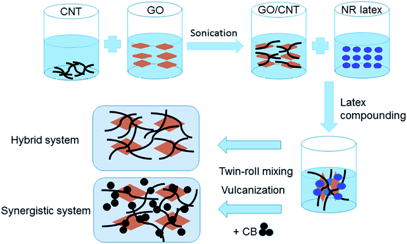 | ||
| Fig. 1 Schematic description of the latex mixing method used for the preparation of the GO/CNT/NR composites and GO/CNT/CB/NR composites. | ||
2.3 Measurement and characterization
The dispersion state of GO/CNT and GO/CNT/CB within the NR matrix was examined by using scanning electron microscope (SEM, JEOL JSM-5900LV) and transmission electron microscope (TEM, FEI TecnaiG2 F20 S-TWIN). Mechanical properties were measured on a material testing machine (Instron 5567) at room temperature with a tensile speed of 500 mm min−1. For Mullins effect, the samples were stretched to an increasing strain (100%, 200%, 300%, 400%) by cycling twice. For the Payne effect, samples were measured at room temperature at 1 Hz in the dynamic strain range 0–60% with a Q800 dynamic mechanical device of TA Corp (New Castle, Delaware).The fatigue test were conducted on edge-notched prismatic specimens, the dimensions of specimens is 60 mm (gage length), 25 mm (width), 2 mm (thickness). The edge of specimens were cut with an initial crack of length of around 5 mm by a sharp blade. The specimens were subjected to tension–tension fatigue testing with a displacement-controlled mode in MTS810 at room temperature. The displacement was prescribed as a sinusoidal pulse at a frequency of 3 Hz with a maximum strain of 0.2 and an R ratio (R ratio is defined as the ratio of minimum to maximum deformation of rubber) is 0. The crack length was measured by vernier caliper every 5000 cycles. The dimension of compression specimens is 26 mm (diameter), 13 mm (thickness). In this procedure, the dynamic strain increases (ε = 5%, 10%, 20%, 30%, 40%, 50%) after 10![[thin space (1/6-em)]](https://www.rsc.org/images/entities/char_2009.gif) 000 cycles. During test, the heat build-up of specimens was measured by infrared imaging devices (FLIR T420, Sweden). The thermal conductive coefficient of sample was measured by LFA (HOT DISK 2500-OT, Sweden).
000 cycles. During test, the heat build-up of specimens was measured by infrared imaging devices (FLIR T420, Sweden). The thermal conductive coefficient of sample was measured by LFA (HOT DISK 2500-OT, Sweden).
3. Result and discussion
3.1 Mechanical properties of NR composites
The striking synergistic reinforcement has been achieved in NR composites filled with GO/CNT hybrid fillers and CB. As illustrated in Fig. 2, the mechanical properties of synergistic systems outperform the hybrid systems. The unfilled NR has a relatively low tensile strength of 20.5 MPa. Incorporation of GO/CNT hybrid fillers slightly increase the tensile strength of NR. As for CB/NR composites, the tensile strength is 21.7 MPa. Intriguingly, a significant reinforcement effect was found by the addition of GO/CNT hybrid fillers in CB/NR composites. The improved mechanical properties of GO/CNT/CB/NR composites were mainly attributed to the strong interaction of filler–filler and filler–rubber.29 The dispersion of fillers is the important factor with regard to filler–filler and filler–rubber interaction under the high filler loadings condition. We suspect that the addition of GO/CNT fillers makes a better dispersion of CB in NR which results in the increased tensile strength. The fracture toughness which is defined as the area under the stress–strain curve is significantly improved, as shown in Fig. 2d. In particular, GO:CNT (1:3)/CB/NR composites have a fracture toughness of 11.08 GJ m−3, which is almost twice as much as that of the CB/NR composites. The fracture toughness is almost related to the tenacity of NR composites upon deformation. Thus we confirm that GO/CNT hybrid fillers can make CB dispersed well in NR, and also prompt CB to form a perfect filler network which possesses a higher effective and reinforced capability.30,31
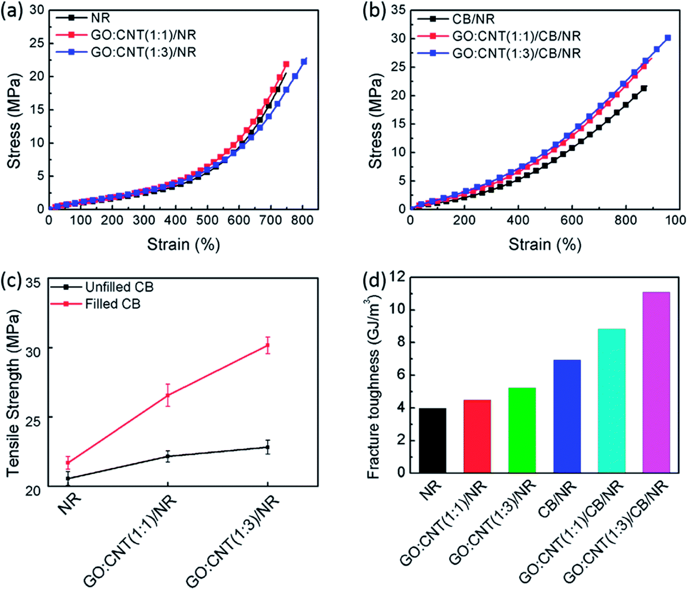 | ||
| Fig. 2 Mechanical properties of NR nanocomposites. (a) Stress–strain of NR filled with hybrid fillers (b) stress–strain of NR filled with hybrid fillers and CB (c) tensile strength of NR filled and unfilled with CB (d) fracture toughness of NR composites. | ||
3.2 Dispersion state of GO/CNT hybrid fillers and CB in NR composites
To characterize the dispersion state of the fillers upon hybridization, SEM and TEM images of GO-CNT/NR composites and GO-CNT/CB/NR composites are shown in Fig. 3. The salient of strips (the red triangle) are the extracting of CNTs cladded with NR matrix and the sheet-like protuberance (the red orthogon) on the fracture surface of composites is the embedding of GO in NR matrix. GO/CNT hybrid fillers are well dispersed in NR due to the surfactant effect of GO for CNT (Fig. 3g). Fig. 3d–f show the SEM images of GO:CNT(1:3)/CB/NR, GO:CNT(1:1)/CB/NR, CB/NR composites and Fig. 3i and j show the dispersion of GO/CNT/CB fillers in NR matrix by TEM. CB fillers aggregate obviously (the red circle indicates the CB aggregation) and some giant cracks have been found, which demonstrates the poor filler dispersion and filler–rubber interaction in CB single filler composites. While the CB filler dispersion state in GO/CNT/CB/NR composites is significantly improved (Fig. 3d, e, i and j), which demonstrates GO/CNT hybrid fillers can prompt CB to disperse well in NR matrix. Compared to CB/NR composites, the fracture surface of GO/CNT/CB/NR composites is much rougher, which is corresponding to the result of fracture toughness of NR composites.
 | ||
| Fig. 3 (a–c) SEM diagrams of GO:CNT(1:3)/NR, GO:CNT(1:1)/NR, NR (d–f) SEM of GO:CNT(1:3)/CB/NR, GO:CNT(1:1)/CB/NR, CB/NR (g–j) TEM diagrams of GO/CNT/NR, GO/CNT/CB/NR (the red arrows represent GO nanosheet, the blue arrows represent CNT, the black arrow represent CB). | ||
It is noteworthy that parts of CNT strings and CB particles were absorbed on the surface of GO sheet which could form a hybrid network architecture efficiently (Fig. 3i and j, the black cycle represent GO/CNT hybrid fillers (or GO, CNT) absorb the CB on the surface). The synergistic intercalation among the GO nanosheets, string-like CNTs and CB particles could inhibit their re-agglomeration and form developed network architecture.32,33 Hence, it's reasonable to believe that the significant improved CB filler dispersion in NR matrix.
3.3 Payne effect of NR composites
It is commonly believed that the incorporation of fillers in a polymer matrix leads to the formation of filler network, due to the aggregation of fillers and the interaction of filler–filler. When the fillers connect each other well in NR matrix, the fillers will form more perfect filler network efficiently. Generally, the absolute value of storage modulus in the low-strain regime is related to the degree of filler network or filler–filler interaction.34,35In low-strain regime, a strong nonlinear reduction of storage modulus (E′) versus strain, commonly known as Payne effect36 is present in Fig. 4. Due to the partial breakage of filler network, the Payne effect was found and additional energy dissipation was occurred when the strain amplitudes increased.33 In highly filled rubber, the addition of GO/CNT fillers could improve the dispersion of CB in NR matrix, and CB aggregates were bridged through fibrous CNTs and layer-like GO nanosheets to form a more perfect hybrid filler network. Thus, based on strain-amplitude sweeps, a more perfect filler network can improve the load carrying capacity of the filler network in highly filled composites, which also can be the reason of high storage modulus of GO/CNT/CB/NR composites compared to CB/NR composites. The magnitude of the Payne effect are shown in Table 1. As for hybrid system, the GO/CNT/NR composites shows little improvement of storage modulus, because the weak filler network formed with low loading fillers didn't work on modulus of composites efficiently. In synergistic system, the obviously promotion of storage modulus of CB/NR composites with the addition of GO/CNT hybrid fillers, which indicates that the GO/CNT hybrid fillers can synergistically promote CB to form a powerful and efficient network; meanwhile, the powerful filler network represents the strong energy dissipation under deformation.37
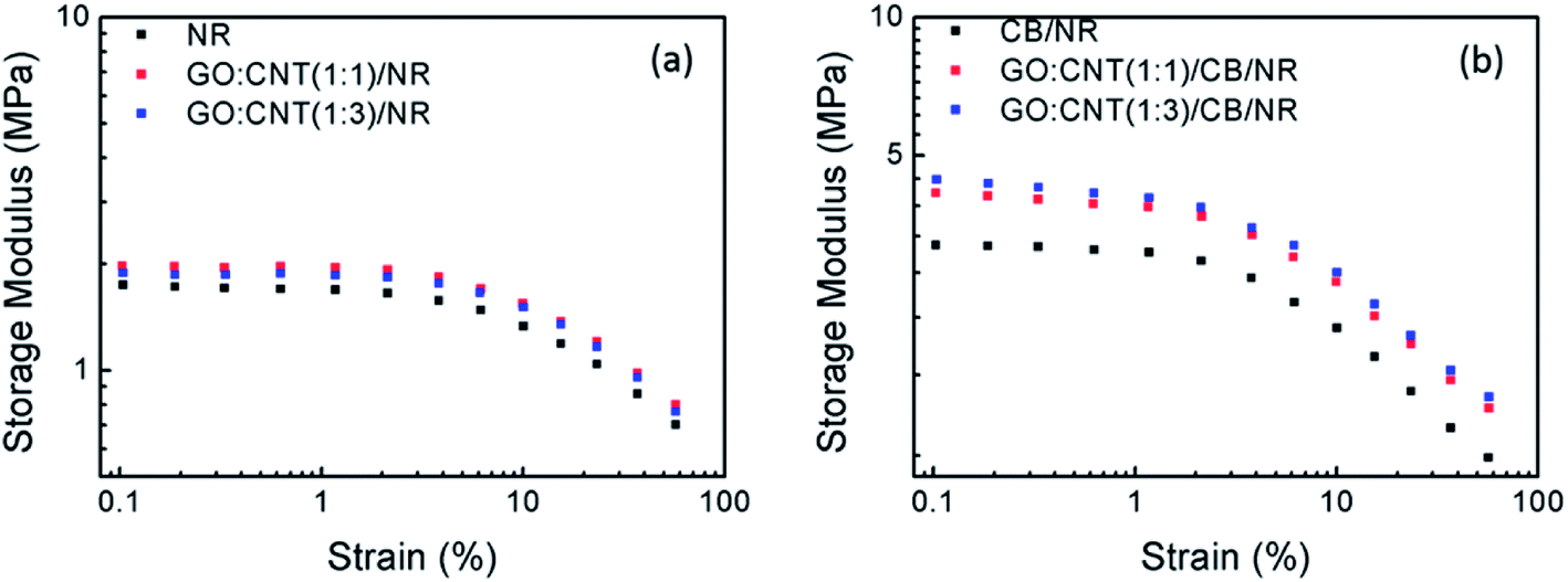 | ||
| Fig. 4 Storage modulus versus strain curve. (a) NR filled with hybrid fillers (b) NR filled with hybrid fillers and CB. | ||
 and
and  represent the storage modulus of NR composites in low strain to large strain)
|
|
|
|
|---|---|---|---|
| NR | 1.641 | 0.748 | 0.893 |
| GO:CNT(1:1)/NR |
2.007 | 0.754 | 1.253 |
| GO:CNT(1:3)/NR |
1.761 | 0.666 | 1.094 |
| CB/NR | 3.202 | 1.076 | 2.126 |
| GO:CNT(1:1)/CB/NR |
4.478 | 1.399 | 3.079 |
| GO:CNT(1:3)/CB/NR |
4.885 | 1.484 | 3.401 |


3.4 Energy dissipation of NR composites
The addition of nanofillers obviously increases the viscoelastic character of the NR composites. Under the cyclic loading condition, the strain cannot follow the stress of NR composites, which shows a distinct hysteresis ring, as shown in Fig. 5(a and c). This phenomenon was known as Mullins effect.38 The Mullins effect is closely related to the change of filler network structure in highly filled NR composites during the cyclic loading. To quantify the Mullins effect, the hysteresis ring was integrated, and the physical name was hysteresis loss. As shown in Fig. 5(b and d), compared with neat NR, the hysteresis loss of GO/CNT/NR composites shows little distinction during the ε ≤ 300% (ε represent the strain of NR composites); when ε ≥ 300%, the hysteresis loss of GO/CNT/NR composites shows much higher than neat NR, which is caused by the breakdown of hybrid filler network during large deformation. However, when the GO/CNT hybrid filler and CB were added in NR together, the hysteresis loss of NR composites was much higher than CB/NR composites under different strain. Here are the reasons we speculate: the layer-like GO and fibrous CNT can serve as bridge to make CB aggregates form more efficient and powerful filler network. The more powerful filler network breakdown, the more energy dissipated. Thus the hysteresis loss can be larger.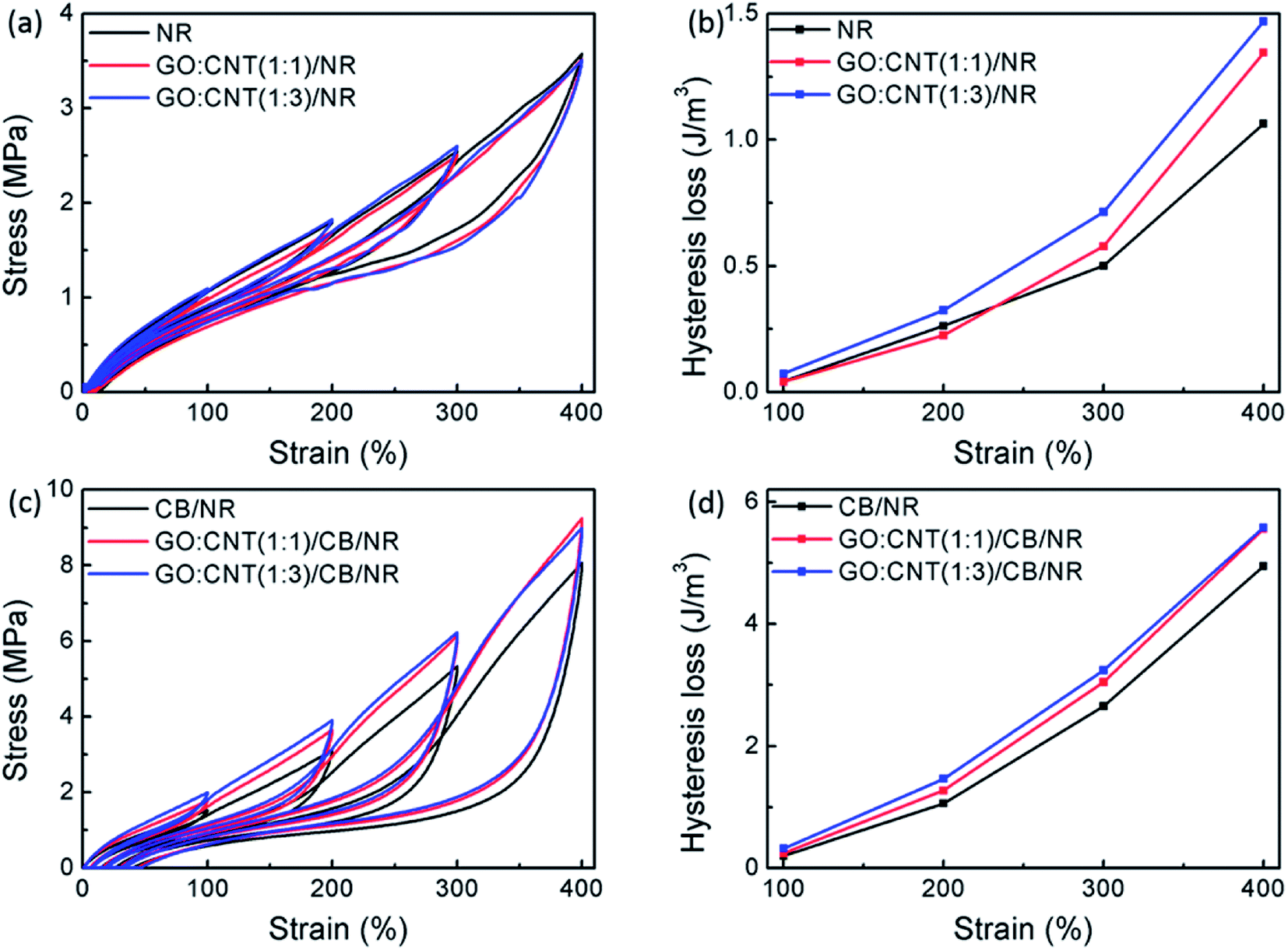 | ||
| Fig. 5 Energy dissipation of NR composites during first tensile cycle. (a) Cyclic hysteresis curves of NR filled with hybrid fillers at different strain (b) hysteresis loss of NR filled with hybrid fillers (c) cyclic hysteresis curves of NR filled with hybrid fillers and CB at different strain (d) hysteresis loss of NR filled with hybrid fillers and CB. | ||
To find out the main reason influence the Mullins effect, the NR composites was subjected to the second tensile cycles with different strains. A remarkable stress-softening effect is shown in Fig. 6(a and c). As a result, during the second tensile cycles, the NR composites are more elastic-like with smaller hysteresis loss, as shown in Fig. 6(b and d). In hybrid system, the hysteresis loss of GO/CNT/NR composites is almost similar with neat NR under different strain, due to the friction among NR molecule is the main reason influence the Mullins effect. In synergistic system, the hysteresis loss of GO/CNT/CB/NR composites was almost same with CB/NR composites when ε ≤ 300%, while larger than CB/NR composites when ε ≥ 300%. Because the perfect filler network was not destroyed entirely. Under large deformation, the partial filler network still dissipated energy and contributed to the hysteresis loss. Thus we can conclude that the more powerful CB network with the addition of GO/CNT hybrid fillers, the larger hysteresis loss of GO/CNT/CB/NR composites compared to CB/NR composites.
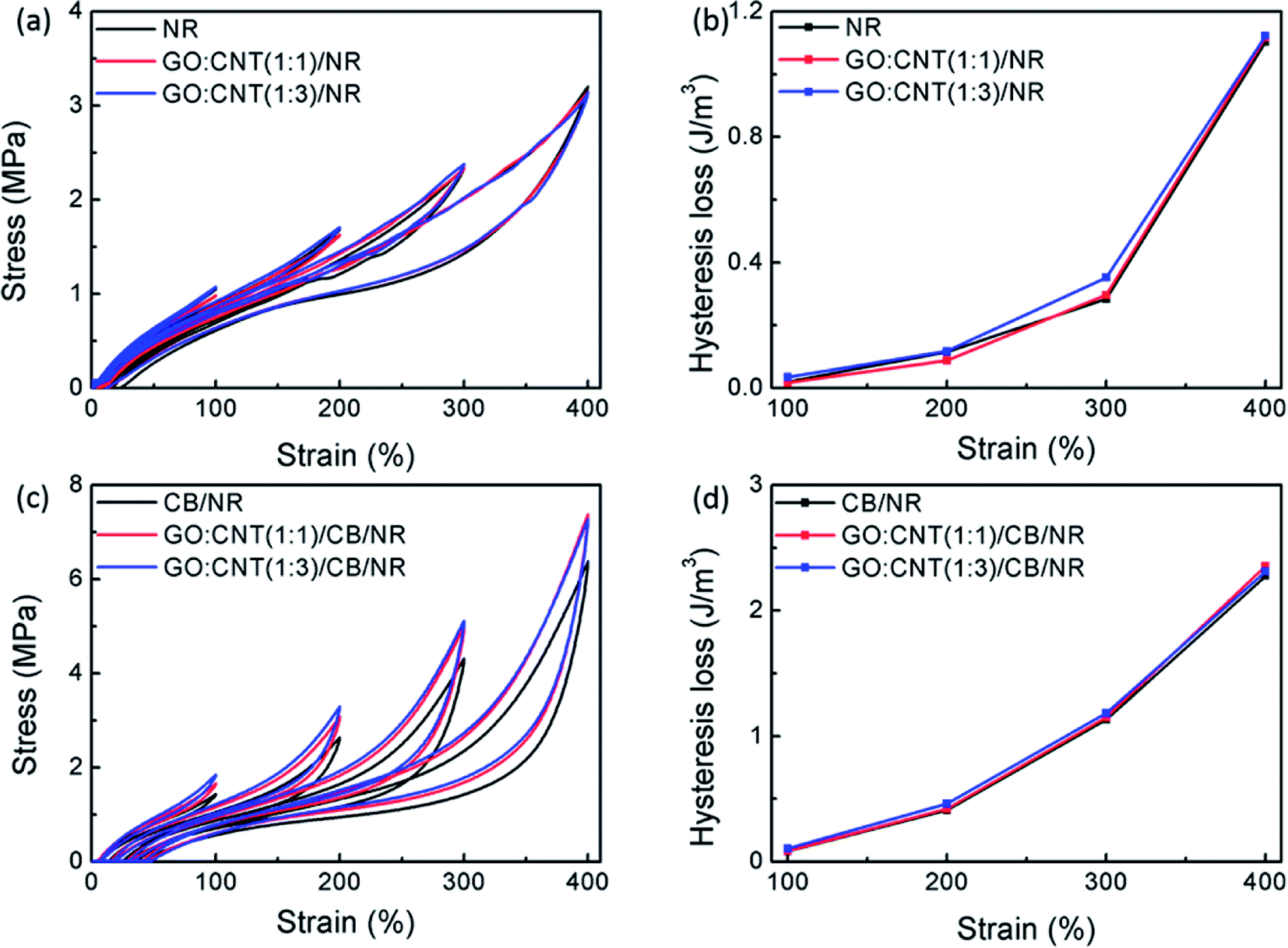 | ||
| Fig. 6 Energy dissipation of NR composites during second tensile cycle. (a) Cyclic hysteresis curves of NR filled with hybrid fillers at different strain (b) hysteresis loss of NR filled with hybrid fillers (c) cyclic hysteresis curves of NR filled with hybrid fillers and CB at different strain (d) hysteresis loss of NR filled with hybrid fillers and CB. | ||
3.5 Crack growth of NR composites
The crack growth resistance is closely related to energy dissipation of filled NR composites. In this section, we studied the crack growth of NR under cyclic loading and the relationship between the crack-growth rate (dc/dn represent the derivative of crack length to cycle number) and the tearing energy (T).39,40 In Fig. 7(a and b), the plots of crack length versus fatigue cycle are presented. It is clear that the GO:CNT(1:1)/NR composites and GO:CNT(1:1)/CB/NR composites show best crack resistance. The magnitude of dc/dn was determined from the sustaining change in the crack length to the corresponding fatigue cycles. The relationship between crack growth rate and tearing energy is shown in Fig. 7(c and d). As for hybrid system, the GO/CNT fillers rarely improve the crack growth of NR composites, even when the ratio of GO:CNT is 1:3, the crack growth resistance of NR composites decreases. The reason of that is the fillers could not dissipate energy efficiently and caused the stress concentration easily. In synergistic system, when T ≤ 2 kJ m−2, the crack growth rate of GO/CNT/CB/NR composites is lower than CB/NR composites. Because the addition of GO/CNT fillers, the CB filler network easily confined the crack growth of NR composites and the CB dispersed homogeneously in NR matrix caused little stress concentration. Thus we can conclude that the addition of GO/CNT hybrid filler will obviously improve the crack growth resistance of CB/NR composites.
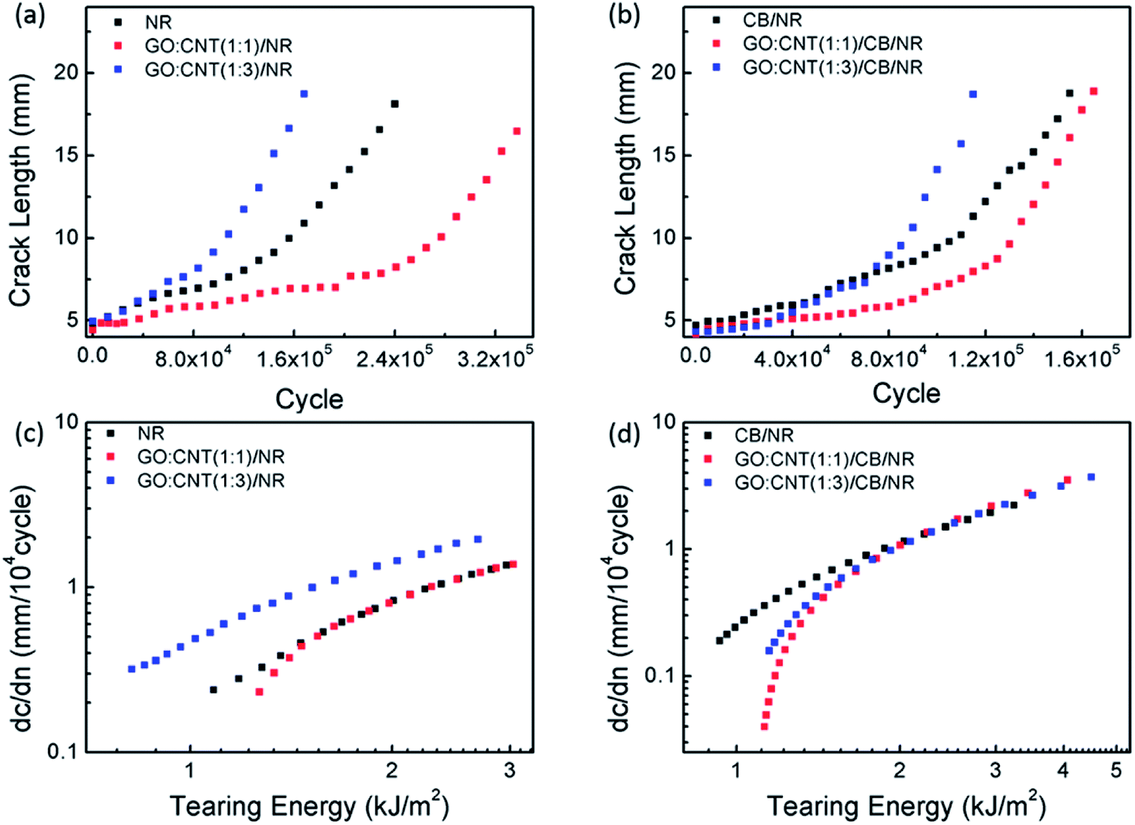 | ||
| Fig. 7 (a and b) Crack length versus the fatigue cycles for the NR composites (c and d) dc/dn (crack growth rates) versus T of NR composites. | ||
3.6 Heat build-up and thermal conductivity of NR composites
Heat build-up is deemed to be one of the most important impact on NR dynamic fatigue. It is mainly determined by the hysteresis loss of NR matrix and the filler network.41 Generally, we know the filler network of high filled NR composites contributes the most hysteresis loss under cyclic deformation. As Fig. 8 shows, during the first 2 × 10⁴ cycles, heat build-up appears little distinction among the NR composites, because the small compression strain did not make large structural change of composites. As the cycles increased, the compression strain became larger, which induced sustainable structural deformation of NR composites. A sustainable structural deformation of NR composites will cause a large amount of energy dissipation transferred to heat. So the heat build-up of NR composites increased with the increasing cycles. While there also appears heat radiation which determined by thermal diffusivity or thermal conductivity, as shown in Table 2. The heat build-up is contradiction to heat radiation, and a competition relationship was formed between them.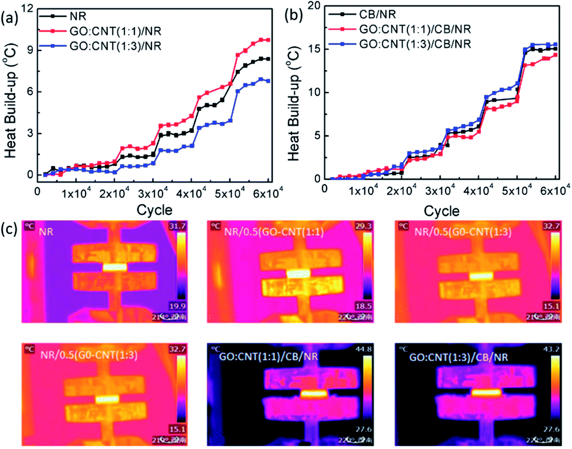 | ||
| Fig. 8 (a) Heat build-up of NR composites filled with hybrid fillers during dynamic fatigue test (b) heat build-up of NR composites filled with hybrid fillers and CB during dynamic fatigue test (c) infrared temperature rise diagram of NR composites. | ||
| NR | GO:CNT(1:3)/NR |
GO:CNT(1:1)/NR |
CB/NR | GO:CNT(1:3)/CB/NR |
GO:CNT(1:1)/CB/NR |
|
|---|---|---|---|---|---|---|
| Thermal conductivity (W m−1K−1) | 0.1624 | 0.1718 | 0.1924 | 0.2706 | 0.2950 | 0.3034 |
| Thermal diffusivity (mm2 S−1) | 0.1891 | 0.2077 | 0.2268 | 0.4660 | 0.5956 | 0.7948 |
With regard to the synergistic system, the heat build-up of GO:CNT(1:1)/CB/NR composites is smaller than CB/NR, which indicated that the better dispersion of CB and the more efficient filler network can greatly prompt the thermal conductivity of NR composites, thus leading to a smaller heat build-up compared to CB/NR. Herein, we can conclude that the introduction of GO/CNT hybrid fillers can reduce the fatigue heat build-up of CB/NR composites.
4. Conclusions
In conclusion, an obvious synergistic reinforcement was achieved by the incorporation of GO/CNT hybrid fillers and CB into NR matrix. With the addition of GO/CNT hybrid fillers, improved dispersion state of CB in NR matrix was achieved. Moreover, the improved dispersion of fillers led to the formation of a more robust and efficient network, which improved the modulus and energy dissipation of NR composites. The introduction of GO/CNT hybrid fillers and CB in NR matrix significantly improved the fatigue crack growth resistance and reduced the heat build-up of NR composites. This provides a good basis for the preparation of natural rubber composite materials with excellent mechanical properties and outstanding fatigue performance.Conflicts of interest
There are no conflicts to declare.Acknowledgements
This work was financially supported by the National Natural Science Foundation of China (grant No. 51333003) and Special Fund for Agro-scientific Research in the Public Interest (201403066-1). We also appreciate Guiping Yuan for the great help of TEM test in Sichuan University analysis and testing center.References
- A. D. Roberts, Natural Rubber Science and Technology, Oxford University Press, 1988 Search PubMed.
- S. Trabelsi, P.-A. Albouy and J. Rault, Macromolecules, 2002, 35(27), 10054–10061 CrossRef CAS.
- B. Adhikari, A. K. Ghosh and S. Maiti, J. Polym. Mater., 2000, 17, 101–125 CAS.
- A. R. Payne and R. E. Whittaker, Composites, 1970, 1(4), 203–214 CrossRef CAS.
- G. R. Hamed and J. Zhao, Rubber Chem. Technol., 1998, 71, 157 CrossRef CAS.
- G. R. Hamed and M. Y. Huang, Rubber Chem. Technol., 1998, 71, 846 CrossRef CAS.
- G. R. Hamed and B. H. Park, Rubber Chem. Technol., 1999, 72, 946 CrossRef.
- G. R. Hamed and N. Rattanasom, Rubber Chem. Technol., 2002, 75, 935 CrossRef CAS.
- G. R. Hamed and A. A. Al-Sheneper, Rubber Chem. Technol., 2003, 76, 436 CrossRef CAS.
- Y. Nie and G. Huang, et al., J. Appl. Polym. Sci., 2010, 117, 3441–3447 CrossRef CAS.
- S. Iijima, P. Ajayan and T. Ichihashi, Phys. Rev. Lett., 1992, 69, 3100 CrossRef CAS PubMed.
- S. Bhattacharyya, C. Sinturel, O. Bahloul, M. L. Saboungi, S. Thomas and J. P. Salvetat, Carbon, 2008, 46(7), 1037–1045 CrossRef CAS.
- P. Junkong, et al., Polym. Test., 2015, 41, 172–183 CrossRef CAS.
- H. Zhang, et al., Micro Nano Lett., 2017, 12(2), 117–122 Search PubMed.
- T. Kuila, et al., Prog. Polym. Sci., 2010, 35, 1350–1375 CrossRef.
- G. Wang, J. Yang, J. Park, X. Gou, B. Wang and H. Liu, et al., J. Phys. Chem. C, 2008, 112, 8192–8197 CAS.
- G. Wang, X. Shen, B. Wang, J. Yao and J. Park, Carbon, 2009, 47, 1359–1364 CrossRef CAS.
- X. Li, X. Wang, L. Zhang, S. Lee and H. Dai, Science, 2008, 319, 1229–1231 CrossRef CAS PubMed.
- P. Blake, P. D. Brimicombe, R. R. Nair, T. J. Booth, D. Jiang and F. Schedin, et al., Nano Lett., 2008, 8, 1704–1708 CrossRef PubMed.
- A. K. Geim and K. S. Novoselov, Nat. Mater., 2007, 6, 183–191 CrossRef CAS PubMed.
- D. R. Dreyer, et al., Chem. Soc. Rev., 2009, 39, 228–240 RSC.
- C. Soldano, et al., Carbon, 2010, 48, 2127–2150 CrossRef CAS.
- H. Bai, et al., J. Phys. Chem. C, 2011, 115, 5545–5551 CAS.
- C. Rao, et al., Angew. Chem., Int. Ed., 2009, 48, 7752–7777 CrossRef CAS PubMed.
- D. A. Dikin, et al., Nature, 2007, 448, 457–460 CrossRef CAS PubMed.
- H. Pang, et al., J. Polym. Res., 2013, 20, 304 CrossRef.
- T. Lu, et al., J. Appl. Polym. Sci., 2017, 134, 44848 CrossRef.
- H. Li, J. Mater. Chem. A, 2015, 3, 22385 CAS.
- J. Frohlich, et al., Composites, Part A, 2005, 36, 449–460 CrossRef.
- Y. Q. Li, T. Y. Yang, T. Yu, L. X. Zheng and K. Liao, J. Mater. Chem., 2011, 21, 10844 RSC.
- J. Liu, S. Wu, Z. Tang, T. Lin, B. Guo and G. Huang, Soft Matter, 2015, 11, 2290 RSC.
- G. Yang, et al., J. Appl. Polym. Sci., 2015, 132, 41832 Search PubMed.
- B. Dong, et al., J. Appl. Polym. Sci., 2015, 132, 42075 Search PubMed.
- G. Kraus, J. Appl. Polym. Sci., 1984, 39, 75 CAS.
- Z. Y. Zhu, T. Thompson, S. Q. Wang, E. D. von Meerwall and A. Halasa, Macromolecules, 2005, 38, 8816 CrossRef CAS.
- A. R. J. Payne, Appl. Polym. Sci., 1962, 6, 57 CrossRef CAS.
- V. Kerchman and C. Shaw, Rubber Chem. Technol., 2003, 76, 386 CrossRef CAS.
- Z. Tang and F. Chen, et al., Polym. Chem., 2017, 8, 4659–4672 RSC.
- R. S. Rivlin and A. G. Thomas, J. Polym. Sci., 1953, 10, 291–318 CrossRef CAS.
- G. J. Lake and A. G. Thomas, Proc. R. Soc. London, Ser. A, 1967, 300, 108–119 CrossRef CAS.
- Z. H. Wang, Y. L. Lu, J. Liu, Z. M. Dang, L. Q. Zhang and W. M. Wang, J. Appl. Polym. Sci., 2011, 119, 1144 CrossRef CAS.
Footnote |
| † Electronic supplementary information (ESI) available. See DOI: 10.1039/c7ra12830d |
| This journal is © The Royal Society of Chemistry 2018 |