 Open Access Article
Controlling nanodomain morphology of epoxy thermosets templated by poly(caprolactone)-block-poly(dimethylsiloxane)-block-poly(caprolactone) ABA triblock copolymer
Jingyi Yang ,
Quan Zhou
 *,
Kang Shen,
Ning Song and
Lizhong Ni
East China University of Science and Technology, China. E-mail: qzhou@ecust.edu.cn
First published on 18th January 2018
Abstract
In this paper, triblock copolymer was incorporated into epoxy to prepare nano thermosets. After studying the compatibility between polydimethylsiloxane (PDMS), polycaprolactone (PCL) and bisphenol A epoxy resin (E-54), poly(caprolactone)–poly(dimethylsiloxane)–poly(caprolactone) (PCL-b-PDMS-b-PCL) triblock copolymer was incorporated into bisphenol A epoxy resin (E-54) and cured with DDS. A nano structure was formed and the size of the spherical phase became larger with increasing PCL-b-PDMS-b-PCL. According to the fact that TGDDM/PCL was compatible and TGDDM/PDMS was incompatible during the curing reaction, the mechanism of nano structure formation was self-assembly. The factors of influencing nano structure formation were discussed with regard to different curing temperatures and accelerators. Curing kinetics was utilized to study the effect of accelerator on nano structure formation.
1 Introduction
Epoxy resins are widely used as matrices for fiber-reinforced composites owing to their excellent mechanical performance and processing ability. However, their application in some fields was limited because of high crosslinking density. One of the effective routines of toughness improvement is to incorporate polymeric modifiers, such as elastomers1–7 and thermoplastics,8–17 into thermosetting matrix to form fine morphological structures. Liquid rubbers such as carboxyl-terminated butadiene–acrylonitrile rubber (CTBN), amine-terminated butadiene–acrylonitrile rubber (ATBN) have been utilized to improve toughness.18–20 Nevertheless, these elastomers with unsaturated structures are prone to a lack of thermal stability and oxidation resistance. Organic silicone polymers possess the properties better than the unsaturated liquid rubbers, such as thermal stability, moisture resistance and good electrical performance. However, polysiloxanes have poor compatibility with the uncured epoxy resin due to the big difference in solubility parameter, leading to the macroscopic phase in thermosets.In epoxy thermosets modified with elastomers or thermoplastics, the control of morphology is generally based on reaction-induced phase separation (RIPS). The modified epoxy thermosets would display the phase separated morphology on the macroscopic scale, for the modifiers are some linear homopolymers or random copolymers.21 In recent years, it is recognized that the formation of nanostructures in thermosets could further optimize the interactions between thermoset matrix and modifiers and thus provide thermosets with improved properties. With the deep study of block copolymers, the mechanism of phase separation has been gradually recognized. In view of the phase separation of block copolymers in epoxy resin, the mechanism is mainly defined reaction-induced and self-assembly phase separation.21–37
Roy l'Abee et al.22 studied the deformation mechanisms of sub-micrometer thermoplastic vulcanizates obtained by reaction-induced phase separation of miscible poly(ε-caprolactone)/dimethacrylate systems. It showed a significant increase in elongation at break and improvement of compression set when reducing the rubber particle size from 520 to 80 nm, which was attributed to an increased interfacial adhesion due to the grafting of PCL chains onto the rubber particles and changes in the spherulite structure of the PCL matrix due to a nucleating effect of the grafted rubber particles. David and his colleagues23 studied PS–PB–PtBMA triblock system, which generates three specific regions with core–shell body centred cubic packing. The ordered phases are generated via the self-assembly of minority component microdomains immersed in the matrix of another polymeric component with a higher composition separated by continuous interphases of pure component microdomains. The body centred cubic phase exhibits regular and irregular spherical morphologies and these are controlled by varying the volume fraction of the homopolymeric components and by the segregation degree between different components. Bates et al.21,24 have proposed an approach to attaining nanostructures by incorporating amphiphilic block copolymers. In this case, the precursors of thermosets acted as the selective solvents of block copolymers and some self-assembly microphases such as lamellar, bicontinuous, cylindrical, and spherical structures were formed in the blends depending on the blend composition before curing reaction. These nanostructures could be further fixed with introduction of hardeners and subsequent curing.
Mülhaupt and his coworkers38,39 investigated the modification of epoxy resin with a poly(ε-caprolactone)-block-polydimethylsiloxane-block-poly(ε-caprolactone) triblock copolymer (PCL-b-PDMS-b-PCL). It is noted that the introduction of 5 wt% of triblock copolymer lead to a significant improvement in toughness whereas the short time mechanical properties (strength, E modulus) was not obviously decreased. It was found that spherical PDMS particles with the size of about 20 nm in diameter are uniformly dispersed in the continuous epoxy-rich phase. However, the formation mechanism of the nanodomains was not clearly illuminated. Marija V. Pergal et al.40 synthesized novel siloxane–urethane copolymers based on MDI/BD as the hard and high content of PCL–PDMS–PCL as the soft segments by two-step polyaddition reactions. It was studied that the spherulites of the α,ω-dihydroxy-(PCL–PDMS–PCL) copolymer were smaller than that of prepolymer, which can be explained that the urethane block in polymer chains restricted crystallization of the PCL segments. Moreover, the contact angle value, i.e., hydrophobicity, increased with increasing of PDMS content. Iscender Yilgör et al.41 prepared PCL–PDMS–PCL copolymer by ring-opening polymerization. Thermal characterization of the copolymer indicated the formation of microphase separated morphologies. Surface enrichment is showed clearly by PDMS and surface morphology strongly affected the protein adsorption and the biocompatibility of the copolymers.
Guo et al.42 reported the thermosetting blends of epoxy resin with poly(ethylene oxide)-block-polydimethylsiloxane diblock copolymer (PEO-b-PDMS). The composition-dependent nanostructures were formed in the thermosets with 10–50 wt% of PEO-b-PDMS. It was proposed that the diblock copolymer behaved as a template to the formation of the nanostructured thermosets via self-assembly mechanism. Heng and his coworkers43 studied the formation mechanism of nanostructures of PS-b-PCL-b-PDMS-b-PCL-b-PS pentablock copolymer. It was found that PDMS subchain was first self-assembled into spherical prior to curing, then the preformed PDMS sphere acted as the templates of the reaction-induced microphase separation of PS subchain to form “core–shell” nanostructures, where the rigid PS as the “shell” and the flexible PDMS as the “core”.
Xu and his colleagues44 incorporated poly(ε-caprolactone)-block-polydimethylsiloxane-block-poly(ε-caprolactone) triblock copolymer (PCL-b-PDMS-b-PCL) into epoxy resin and nanostructured thermosetting blends were prepared. The PDMS microdomains with sizes of 10–20 nm were dispersed in a continuous epoxy matrix. The formation of the nanostructures in the thermosetting composites was judged to follow the self-assembly mechanism in terms of the difference in miscibility of PDMS and PCL subchains with epoxy resin after and before curing reaction. Hu et al.45 investigated that the epoxy thermosets containing polysulfone-block-polydimethylsiloxane diblock copolymer (PSF-b-PDMS) possessed the microphase separated morphological structures. Depending on the content of the PSF-b-PDMS diblock copolymer, the spherical particles with the size of 50–200 nm in diameter were dispersed into the continuous epoxy matrices. It is noted that the epoxy resin was significantly toughened in terms of the measurement of critical stress field intensity factor (KIC). In views of the previous studies, we proposed that nanostructures could be formed in thermosetting blends of epoxy resin with PCL-b-PDMS-b-PCL by selecting appropriate curing systems via self-assembly mechanism.
The goal of this work is twofold: to study the morphological evolution developed by PCL-b-PDMS-b-PCL copolymers inside thermosets in order to propose a possible nanostructuration mechanism, and to investigate the effect of different accelerating agents tris(dimethylaminomethyl)phenol (DMP-30) and 2-ethyl-4-methylimidazole (2,4-EMI) on the formation of nanostructures in thermosetting blends of epoxy resin and PCL-b-PDMS-b-PCL, which was verified by curing kinetics. It is expected that we can selectively control the microphase separation of PDMS subchains by choosing the appropriate accelerator whereas the PCL subchains remain miscible with the crosslinked epoxy networks.
2 Experimental
2.1 Materials
The epoxy precursor, diglycidyl ether of bisphenol A (DGEBA) with epoxide equivalent weight of 179–192 was supplied by Shanghai Research Institute of Synthetic Resins. 4,4′-Diaminodiphenylsulfone (DDS) was used as the curing agent, obtained from Sinopharm Chemical Reagent Co., China. The accelerating agents, tris(dimethylaminomethyl) phenol (DMP-30) and 2-ethyl-4-methylimidazole (2,4-EMI), were purchased from Sinopharm Chemical Reagent Co., Ltd and Aldrich Co., China, respectively. 3-Hydroxypropyl-terminated polydimethylsiloxane (PDMS) with Mn = 562 was obtained from Momentive Co., China. The monomer, ε-caprolactone (ε-CL) was purchased from Aldrich Co., China and it was dried over calcium hydride (CaH2) and treated by reduced pressure distillation before use. The catalyst, stannous octanoate [Sn(Oct)2] was obtained from Aldrich Co., China. The solvents such as toluene, tetrahydrofuran (THF) and petroleum ether were of analytical grade, purchased from Shanghai Linfeng Chemical Reagent Co., China.2.2 Synthesis of PCL-b-PDMS-b-PCL triblock copolymer
PCL-b-PDMS-b-PCL triblock copolymer was synthesized via the ring-opening polymerization (ROP) of ε-CL in the presence of 3-hydroxypropyl-terminated polydimethylsiloxane (PDMS) with stannous octanoate [Sn(Oct)2] as the catalyst. Typically, 1.35 g (2.4 mmol) PDMS, 10.85 g (95.2 mmol) ε-CL and 0.03 g Sn(Oct)2 (in the solution of anhydrous toluene) were added to a 100 mL flask equipped with a magnetic stirrer. The pump–freeze–thaw cycle was repeated for three times to eliminate moisture in ε-CL. With the protection of dry nitrogen, the flask was immersed into oil bath at 120 °C to initiate the ring-opening polymerization. After the polymerization was carried out for 48 h, the system was cooled to room temperature and THF was added. Then the solution was dropped into a great amount of petroleum ether to eliminate residual monomer. The precipitate was dried in a vacuum oven at 40 °C for 24 h and the product (11.16 g) was accessed with the yield of 91.5%.2.3 Preparation of epoxy thermosets containing PCL-b-PDMS-b-PCL triblock copolymer
The desired amount of PCL-b-PDMS-b-PCL triblock copolymer was added to DGEBA with continuous stirring at 130 °C until the mixtures became homogenous and transparent. 4,4′-Diaminodiphenylsulfone (DDS) was added with continuous stirring until the full dissolution of the curing agent and then the accelerating agent, tris(dimethylaminomethyl) phenol (DMP-30) or 2-ethyl-4-methylimidazole (2,4-EMI), was added. The mixtures were poured into Teflon molds and cured at 180 °C for 2 h.2.4 Characterization and measurements
 | (1) |
3 Results and discussion
3.1 Synthesis of PCL-b-PDMS-b-PCL triblock copolymer
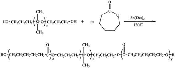
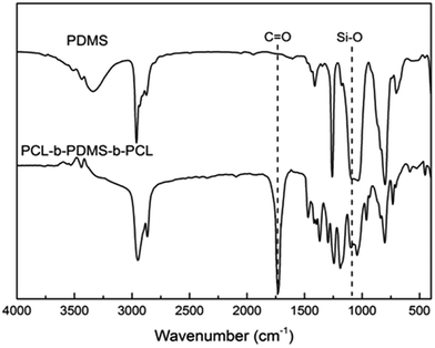
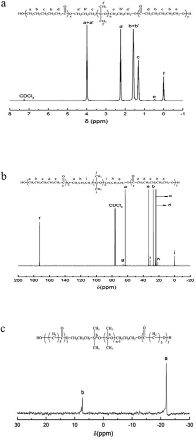
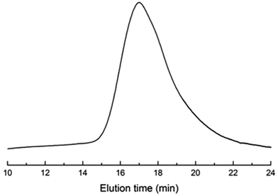
In our work, the ring-opening polymerization of ε-CL was carried out with PDMS and Sn(Oct)2 as shown in Scheme 1. In the reaction, the monohydroxyl-terminated polydimethylsiloxane (PDMS-OH) was used to initiate the ring-opening polymerization of ε-caprolactone with Sn(Oct)2 as the catalyst; the hydroxyl-terminated polydimethylsiloxane-block-poly(ε-caprolactone) diblock copolymer (PDMS-b-PCL-OH) was obtained. The hydroxyl-terminated PDMS-b-PCL diblock copolymer was further employed to react with ε-caprolactone to obtain the PCL-b-PDMS-b-PCL ABA triblock copolymer. Shown in Fig. 1 are the FTIR spectra of the PCL-b-PDMS-b-PCL triblock copolymer and PDMS. In the FTIR spectrum of PDMS, the absorption band at 1082 cm−1 is assignable to the stretching vibration of Si–O bonds of this polymer. It is seen that this band also appeared in the FTIR spectrum of the product, which indicates the presence of PDMS subchain in the polymer. In addition, the stretching vibration of carbonyl groups is seen at 1727 cm−1, which is ascribed to the ester structural unit in PCL subchain.Fig. 2 presents the NMR spectrum of the triblock copolymer. As indicated in the NMR spectrum, the simultaneous appearance of the resonance characteristic of PCL and PDMS protons indicates that the resulting product combines the structural features of PCL and PDMS, i.e., the PCL-b-PDMS-b-PCL triblock copolymer was successfully obtained. The GPC profile is presented in Fig. 3, which shows that the GPC curve displays a unimodal peak, suggesting that no homopolymers are detected. The molecular weight of Mn = 9690 together with Mw/Mn = 1.20 were determined relative to polystyrene standard. Moreover, the degree of polymerization of PCL and PDMS block is 40 and 7.8.
3.3 The compatibility of epoxy resin and block copolymer
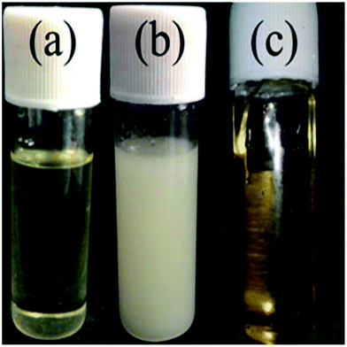
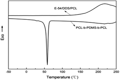
To investigate the micro-phase of the epoxy thermoset modified with the PCL-b-PDMS-b-PCL block copolymer, it is of great importance to have a clear idea of the compatibility of epoxy resin and monopolymers in advance. Before curing reaction, the blend of epoxy and PCL shows a clear and homogeneous system (Fig. 4a), whereas the blend of epoxy and PDMS shows a turbid and heterogeneous system (Fig. 4b). For the blend of epoxy and PCL-b-PDMS-b-PCL, it also presents a clear solution before curing (Fig. 4c). Shown in Fig. 5 are the DSC curves of PCL-b-PDMS-b-PCL and the blend of epoxy and PCL. It is seen that the block copolymer exhibited a melting point at 56 °C which is attributed to the PCL block. For the blend, no evident melting point was observed, which indicates that the epoxy has a good compatibility with PCL before curing.After curing, the epoxy thermoset modified with PCL and PDMS still maintained transparent and turbid, respectively (Fig. 6a and b). As to the epoxy thermoset modified with PCL-b-PDMS-b-PCL block copolymer, the transparency depended on the accelerant. For the DMP-30, a turbid thermoset was obtained (Fig. 6c). For the EMI, however, a transparent thermoset was prepared (Fig. 6d). Scanning electron microscope was used to have a further study on the macro-phase separation. Before the operation, the thermosets were etched by dichloromethane for 30 min. No obvious second phase was seen in the SEM paragraph of the thermoset modified with PCL (Fig. 7a). Conversely, the holes with 20–40 μm in diameter appeared in the thermoset modified with PDMS (Fig. 7b). For epoxy with block copolymer and 2,4-EMI, no evident phase separation was observed. These results indicate that the separation may occur in micro-phase.
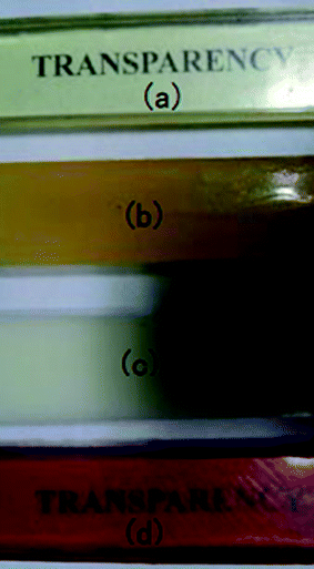 | ||
| Fig. 6 The images of epoxy thermoset modified with PCL (a), PDMS (b), block copolymer and DMP-30 (c) and block copolymer and 2,4-EMI (d). | ||
 | ||
| Fig. 7 The SEM photographs of epoxy thermoset modified with PCL (a), PDMS (b) and block copolymer and 2,4-EMI (c). | ||
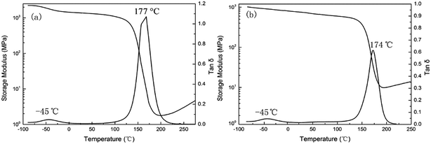
To study the compatibility of PCL-b-PDMS-b-PCL and E-54 epoxy resin matrix with two different accelerators, dynamic mechanical thermal analysis (DMTA) is used, as shown in Fig. 8. The two epoxy resin systems with DDS as the curing agent all have a sharp relaxation peak around 175 °C, which was an α-transformation produced by curing, namely glass epoxy thermosetting material with high elastic state transition (glass transition temperature). The glass transition temperature of the DMP-30 system is 177 °C, and Tg of 2,4-EMI system is 174 °C. The reason why Tg is reduced is that the PCL segment has much influence on PCL-b-PDMS-b-PCL and Tg of PCL is about −60 °C. Moreover, the difference in Tg of the two systems is mainly due to the different compatibility of the PDMS segments in the resin matrix. The PDMS segment is separated from the resin matrix in macroscopically in DMP-30 system, while it isn't separated from the resin matrix in macroscopically in the system of 2,4-MEI. Therefore, the compatibility of 2,4-EMI with the resin matrix is better than that of DMP-30 and the former is affected more by the Tg of the PDMS segment.
3.4 Morphology of thermosets containing PCL-b-PDMS-b-PCL
Before curing, all the mixtures of the epoxy precursors (E-54 and DDS) and PCL-b-PDMS-b-PCL triblock copolymer were homogenous and transparent at room and elevated temperatures. The clarity suggests that the presence of miscible PCL blocks connected to PDMS chain improves the dispersion of PDMS chains in the mixtures. With adding the accelerating agent (2,4-EMI) and curing at 180 °C for 2 h, the thermosetting blends of epoxy resin with PCL-b-PDMS-b-PCL were obtained with the content of PCL-b-PDMS-b-PCL up to 30 wt%. It is seen that all the thermosets containing PCL-b-PDMS-b-PCL triblock copolymer are transparent and homogenous, suggesting that no macroscopic phase separation occurred at least on the scale exceeding the wavelength of visible light. The morphology of the epoxy thermosets was examined by means of transmission electronic microscopy (TEM).Shown in Fig. 9 are the TEM micrographs of the thermosets containing PCL-b-PDMS-b-PCL triblock copolymer. The dark regions are attributed to the domains of PDMS whereas the light to epoxy matrix. It is seen that spherical PDMS particles with the size of 40 nm were homogeneously dispersed into the continuous epoxy matrix (Fig. 9a). With increasing the content of the triblock copolymer, the spherical nanoparticles began to coagulate in the continuous epoxy matrix, and some wormlike nano-domains of PDMS appeared; the epoxy thermosets possessed a combined morphology, in which both spherical PDMS domains and some interconnected PDMS domains were present (Fig. 9b and c). The TEM results indicate that the epoxy thermosets possess the micro-phase separated morphology.
 | ||
| Fig. 9 The TEM micrographs of the nanostructured thermosets containing (a) 10, (b) 20, and (c) 30 wt% of PCL-b-PDMS-b-PCL block copolymer. | ||
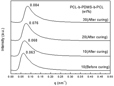
Small-angle X-ray scattering was used to have a further study on the morphology. For the 2,4-MEI as accelerator, the curves with different proportion of PCL-b-PDMS-b-PCL block copolymer all show scattering peaks, which explains the micro-phase structure really exists in the thermosets containing PCL-b-PDMS-b-PCL triblock copolymer (Fig. 10). It shows that the nano-structure has been formed before curing, and the micro-phase structure is fixed in the curing process, which followed by internal self-assembly reaction. The distance between adjacent micro phase could be calculated by the position of scattering peaks in the SAXS curves and Bragg equation L = 2π/qm. The result is shown in the Tables 1 and 2. It is seen that the distance between PDMS micro phase is shortened to some extent. After curing (Table 1). Because the formation of three-dimensional network makes PDMS micro phase gather and its size increases. As the Table 2 shows, the distance between adjacent micro phase is gradually reduced from 92.3 nm to 74.8 nm with the content of PCL-b-PDMS-b-PCL in the thermosets increasing, which is consistent with the results of TEM.
| PCL-b-PDMS-b-PCL (wt%) | Distance of PDMS micro phase (nm) |
|---|---|
| 10 (before curing) | 99.7 |
| 10 (after curing) | 92.3 |
| PCL-b-PDMS-b-PCL (wt%) | Distance of PDMS micro phase (nm) |
|---|---|
| 10 | 92.3 |
| 20 | 82.6 |
| 30 | 74.8 |
3.5 Kinetic study on effect of accelerator on the nano-structure formation structure
To discuss the formation of the nanostructured thermosets, the mechanistic approach comes into consideration. It consists of considering the complete set of reaction steps which constitutes the overall mechanism defining the single-rate equations for each step. The autocatalytic model proposed by Kamal, which takes into account the reactions of the epoxy groups with primary and secondary amines, as well as catalytic (catalyst or impurities) and autocatalytic effects (existing hydroxyl groups), has been applied by assuming equal reactivity of all of the amino hydrogen. The model can be represented by the following equation:
 | (2) |
The constant k1 can be calculated when estimation of the initial reaction rate at α = 0 becomes possible. The kinetic constants k1 and k2 are assumed to follow the Arrhenius form:
 | (3) |
To obtain a first estimation of the reaction order n, eqn (1) can be re-written in the following form:
 | (4) |
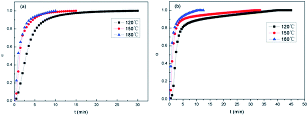
Presented in Fig. 10 are the α–t isothermal curves of E-54/PCL-b-PDMS-b-PCL triblock copolymer. For 2,4-EMI (Fig. 11a), at the same curing temperature, conversion rate gradually increased to 1 when the epoxy group participated in the curing reaction completely. The initial reaction rate increased as the curing temperature rised and it reached higher conversion rate with less time. At higher curing temperature, the curing degree became higher at the same time. For DMP-30 (Fig. 11b), it took longer to make the system fully cure than 2,4-EMI, which resulted in the bigger size of PDMS micro-phase in the thermosets after curing. It's consistent with the SEM results.
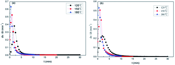
Fig. 12 shows the dα/dt–t isothermal curves of the epoxy thermosets. At the beginning of curing stage, the reaction rate dα/dt isn't equal to 0. The maximum reaction rate occurs after a while, and then dα/dt decreases as time goes on. It suggests that the epoxy resin system is not only a n-grade reaction model, and it has characteristics of Kamal reaction in the curing induction period. As the curing temperature rises, the peak of dα/dt–t isothermal curves becomes sharp and dα/dt reduces to 0 faster. The results show that the activity of epoxy group and dα/dt increases with the rise of curing temperature. At 180 °C, it's found that the maximum reaction rate of 2,4-EMI (Fig. 12a) as accelerator is higher than that of DMP-30 as accelerator (Fig. 12b). And the former takes shorter time to get the maximum reaction rate, which helps to control the micro-phase of PDMS block in PCL-b-PDMS-b-PCL copolymer better.
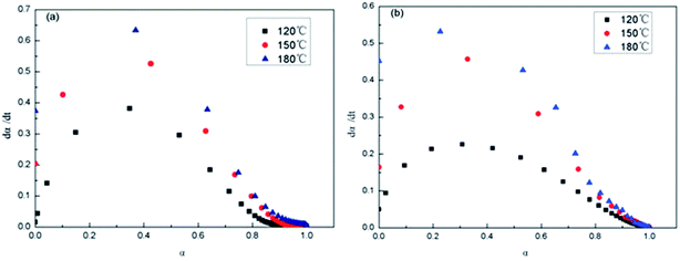
Shown in Fig. 13 are the dα/dt–α isothermal curves of the epoxy thermosets. At the same time and temperature, the reaction rate of 2,4-EMI system was higher than that of DMP-30 system. The data is shown in Table 3. It is seen that dα/dt increases to maximum with α of epoxy group increasing at the initial stage. Then the reaction rate gets down to 0 as the conversion rate increases, which conforms to autocatalytic reaction. Because there is much epoxy group at the initial stage and growing reaction rate makes it decline quickly, which forms three-dimensional net structure and dα/dt gradually decreases. At 180 °C, the system of 2,4-EMI as accelerator gets maximum reaction rate when α becomes 0.23 (Fig. 13a), while that of DMP-30 as accelerator gets maximum reaction rate when α becomes 0.29 (Fig. 13b), which indicates the former could get higher reaction rate with lower α and its formation of three-dimensional net is faster. Thus the phase separation of PDMS micro-phase only occurs in nanometer scale.
| Accelerator | Temperature (°C) | Maximum reaction rate (min−1) | Corresponding conversion rate |
|---|---|---|---|
| 2,4-EMI | 130 | 0.38 | 0.34 |
| 150 | 0.55 | 0.30 | |
| 180 | 0.64 | 0.23 | |
| DMP-30 | 130 | 0.23 | 0.33 |
| 150 | 0.46 | 0.32 | |
| 180 | 0.53 | 0.29 |
The autocatalytic model constants obtained by repeated iteration are shown in Table 4. The reaction orders, m and n, were approximately, respectively. These orders did not seem to vary very much in different temperature.
| Accelerator | Temperature (°C) | m | n | k1 (min−1) | k2 (min−1) |
|---|---|---|---|---|---|
| 2,4-EMI | 130 | 0.92 | 1.76 | 0.049 | 0.108 |
| 150 | 1.03 | 2.18 | 0.166 | 2.776 | |
| 180 | 1.64 | 2.45 | 0.452 | 7.312 | |
| DMP-30 | 130 | 0.78 | 1.53 | 0.015 | 0.089 |
| 150 | 0.69 | 2.05 | 0.146 | 1.811 | |
| 180 | 1.57 | 2.35 | 0.374 | 5.729 |
The reaction orders, m and n, were approximately, respectively. Values of m and n were found to increase when the temperature increased for both systems, but these orders did not seem to vary very much in different temperature. However, the reaction rate constants, k1 and k2, have a great rise, especially for k2, which indicate that the cross-linking reaction depends on temperature largely. In accordance with above results, it can be pointed out that the curing rate curve which has the highest reaction rate is the one that has the highest value of m and n reaction order (Table 4). In this case, the rapid formation of the epoxy three-dimensional network goes against the phase separation of PDMS blocks. From the data, it could be seen that the k1 and k2 of system of 2,4-EMI as accelerator is always bigger than that of DMP-30 as accelerator at the same temperature. So the acceleration of the former is better, which suggests that the effect of different accelerator on the phase separation of PDMS blocks is also different. As a result, 2,4-EMI could lead to get maximum reaction rate with less time, and PDMS blocks can only grow in the epoxy matrix in the nanometer scale.
3.6 Thermal stability and mechanical performance of E-54/PCL-b-PDMS-b-PCL
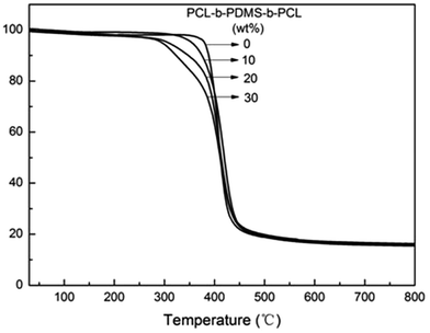
The influence of heat resistance which PCL-b-PDMS-b-PCL had on E-54 was examined by TGA (Fig. 14), and the relevant data was shown in Table 5. It was seen that the weight loss of the nanostructured thermosets occurs mainly between 300 and 450 °C, and the temperatures of initial degradation with 5% mass loss (Td5) are apparently lower than that of the pure E-54 thermosets. E-54 thermosets containing PCL-b-PDMS-b-PCL triblock copolymer had poor thermal resistance compared to the pure E-54 epoxy matrix thermoset. The main reason is the PDMS block of good heat resistance has a lower proportion whereas the PCL block of poor heat resistance has a larger proportion, and the thermal stability of the modified E-54 thermosets decreases.| PCL-b-PDMS-b-PCL (wt%) | Td5 (°C) | Residue at 800 °C (%) |
|---|---|---|
| 0 | 379.9 | 15.7 |
| 10 | 355.4 | 16.1 |
| 20 | 308.3 | 16.3 |
| 30 | 295.9 | 15.6 |
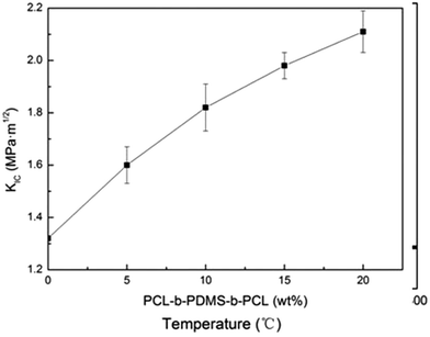
To measure the critical stress intensity factor (KIC), the fracture toughness of the E-54 thermosets containing PCL-b-PDMS-b-PCL triblock copolymer was analysed by using three-point blending tests. Shown in Fig. 15 are the KIC curves of different triblock copolymer content for the thermosets. It showed that modified E-54 thermosets exhibit excellent fracture toughness compared to the neat E-54 thermosets, which indicated that the epoxy thermosets were significantly toughened with the inclusion of triblock copolymer. When the content of PCL-b-PDMS-b-PCL reached 20 wt%, E-54/PCL-b-PDMS-b-PCL, the KIC value of the system was 2.11 MPa m1/2, which was 59.8% higher than that of unmodified E-54 thermosets. The mechanism of toughening is that PDMS blocks homogenously dispersing in the E-54 thermosets enhance the interaction between PDMS nanophase and thermosetting matrix. The spherical micro phase structure of phase separation could produce stress concentration, absorbing outside pressure to some extent, which resulted in excellent toughness of modified E-54 thermosets.
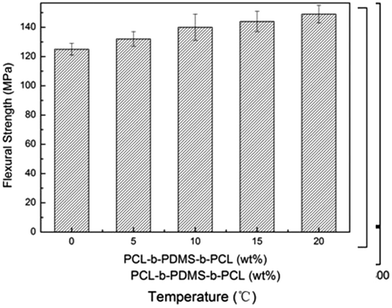
Show in the Fig. 16 are the bending strength of E-54 thermosets containing PCL-b-PDMS-b-PCL triblock copolymer via three-point bending tests. It is seen that the bending strength of modified thermosets are higher than that of unmodified epoxy to some extent and increased with increasing content of PCL-b-PDMS-b-PCL. The maximum bending strength of the E-54 thermosets containing PCL-b-PDMS-b-PCL triblock copolymer is 149.6 MPa, which is 19.4% higher than neat E-54 thermosets. Its reason is same as the mechanism of toughening given above.
3.7 Mechanism of micro-phase separation
The kinetic analysis of the triblock copolymer PCL-b-PDMS-b-PCL could be of significant importance to discuss the mechanism of the formed nanostructure of E-54/PCL-b-PDMS-b-PCL system. By studying the α–t isothermal curves and dα/dt–t isothermal curves of E-54/PCL-b-PDMS-b-PCL, the results shows that there is an induction period during the curing process, which accords with the characteristics of Kamal reaction. Through the Kamal equation fitting, it's founded that the kinetic constant k2 is always much larger than k1. Because k1 represents the autocatalytic reaction at the beginning of curing process, and k2 represents the later process, which shows that autocatalytic reaction mainly exists in the curing reaction of the epoxy resin system. And the result follows the analysis of dα/dt–α isothermal curves. Moreover, the kinetic data also shows accelerant 2,4-EMI can accelerate the reaction rate to a maximum value, and it can make sure that the micro-phase separation will not appear in the PDMS block. The TEM micrographs and SAXA curves also show that microstructure really exists in the triblock copolymer. It's concluded that the triblock copolymer could form the nanostructure following the mechanism of self-assembly reaction, owing to the compatibility of PCL block with E-54 and the incompatibility of PDMS block with E-54 during the curing process, and the nanostructure forms before curing. The formed three-dimensional net structure fixes the split phase after curing and forms sea island structure.4 Conclusions
In our work, triblock copolymer poly(ε-caprolactone)-block-polydimethylsiloxane-block-poly-(ε-caprolactone) (PCL-b-PDMS-b-PCL) was synthesized via the ring-opening polymerization (ROP) of ε-CL in the presence of 3-hydroxypropyl-terminated polydimethylsiloxane (PDMS), which was catalyzed by stannous octanoate [Sn(Oct)2]. The triblock copolymer was further used to prepare nanostructured epoxy thermosets. It was found that the PCL nanophases were always compatible with E-54 whereas PDMS subchains were always incompatible with it. It is judged that the formation of the nanostructure follows the mechanism of self-assembly reaction. Kinetic data supported the contention that higher reaction rate contributed to the formation of nanostructures. The thermal stability decreased to some extent but mechanical performance of the E-54 thermosets was improved, owing to the incorporation of the PCL-b-PDM-b-PCL triblock copolymer.Conflicts of interest
There are no conflicts to declare.References
- J. I. Meijerink, S. Eguchi, M. Ogata, T. Ishii, S. Amagi and S. Numata, et al., Polymer, 1994, 35, 179 CrossRef CAS.
- S. Zheng, H. Wang, Q. Dai, X. Luo and D. Ma, Macromol. Chem. Phys., 1995, 196, 269 CrossRef CAS.
- T. J. Kemp, A. Wilford, O. W. Howarth and T. C. P. Lee, Polymer, 1992, 33, 1860 CrossRef CAS.
- H. S. Y. Hisich, Polym. Eng. Sci., 1990, 30, 493 Search PubMed.
- P. Bussi and H. Ishida, J. Appl. Polym. Sci., 1994, 32, 647 CrossRef CAS.
- R. S. Kumar and M. Alagar, J. Appl. Polym. Sci., 2006, 101, 668 CrossRef CAS.
- R. Thomas, S. Durix, C. Sinturel, T. Omonov, S. Goossens and G. Groeninckx, et al., Polymer, 2007, 48, 1695 CrossRef CAS.
- D. J. Hourston and J. M. Lane, Polymer, 1992, 33, 1397 Search PubMed.
- J. H. Hedrick, I. Yilgor, M. Jurek, J. C. Hedrick, G. L. Wilkens and J. E. McGrath, Polymer, 1991, 13, 2020 CrossRef.
- R. S. Raghava, J. Polym. Sci., Part B: Polym. Phys., 1988, 26, 65 CrossRef CAS.
- J. B. Cho, J. W. Hwang, K. Cho, J. H. An and C. E. Park, Polymer, 1993, 34, 4832 CrossRef CAS.
- S. Zheng, J. Wang, Q. Guo, J. Wei and J. Li, Polymer, 1996, 37, 4667 CrossRef CAS.
- M. A. Hillmyer, P. M. Lipic, D. A. Hajduk, K. Almdal and F. S. Bates, J. Am. Chem. Soc., 1997, 119, 2749 CrossRef CAS.
- P. M. Lipic, F. S. Bates and M. A. Hillmyer, J. Am. Chem. Soc., 1998, 120, 8963 CrossRef CAS.
- J. Mijovic, M. Shen, J. W. Sy and I. Mondragon, Macromolecules, 2000, 33, 5235 CrossRef CAS.
- B. Francis, V. L. Rao, G. V. Poel, F. Posada, G. Groenincks and R. Ramaswamy, et al., Polymer, 2006, 47, 5411 CrossRef CAS.
- B. Francis, S. Thomas, J. Jose, R. Ramaswamy and V. L. Rao, Polymer, 2005, 46, 12372 CrossRef CAS.
- E. M. Yorkgitis, N. S. Eiss, C. Tran, G. L. Wilkes and L. E. McGrath, Adv. Polym. Sci., 1985, 72, 70 CrossRef.
- A. F. Yee and R. A. Pearson, J. Mater. Sci., 1986, 21, 2462 CrossRef CAS.
- J. I. Meijerink, S. Eguchi, M. Ogata, T. Ishii, S. Amagi, S. Numata and H. Sashima, Polymer, 1994, 35, 179 CrossRef CAS.
- M. A. Hillmyer, P. M. Lipic, D. A. Hajduk, K. Almdal and F. S. Bates, J. Am. Chem. Soc., 1997, 119, 2749 CrossRef CAS.
- R. l'Abee, M. van Duin and H. Goossens, Soft Matter, 2017, 13, 6905 RSC.
- D. A. González-Pizarro, C. Soto-Figueroa, M. del Rosario Rodríguez-Hidalgo and L. Vicente, Soft Matter, 2017, 10, 1039 Search PubMed.
- P. M. Lipic, F. S. Bates and M. A. Hillmyer, J. Am. Chem. Soc., 1998, 120, 8963 CrossRef CAS.
- Q. Guo, R. Thomann and W. Gronski, Macromolecules, 2002, 35, 3133 CrossRef CAS.
- Q. Guo, R. Thomann and W. Gronski, Macromolecules, 2003, 36, 3635 CrossRef CAS.
- J. Lee, G. P. Yandek and T. Kyu, Polymer, 2005, 46, 12511 CrossRef CAS.
- S. Ritzenthaler, F. Court, E. Girard-Reydet, L. Leibler and J. P. Pascault, Macromolecules, 2002, 35, 6245 CrossRef CAS.
- S. Ritzenthaler, F. Court, E. Girard-Reydet, L. Leibler and J. P. Pascault, Macromolecules, 2003, 36, 118 CrossRef CAS.
- H. Kosonen, J. Ruokolainen, P. Nyholm and O. Ikkala, Macromolecules, 2001, 34, 3046 CrossRef CAS.
- H. Kosonen, J. Ruokolainen, P. Nyholm and O. Ikkala, Polymer, 2001, 42, 9481 CrossRef CAS.
- R. B. Grubbs, J. M. Dean, M. E. Broz and F. S. Bates, Macromolecules, 2000, 33, 9522 CrossRef CAS.
- V. Rebizant, V. Abetz, T. Tournihac, F. Court and L. Leibler, Macromolecules, 2003, 36, 9889 CrossRef CAS.
- J. M. Dean, N. E. Verghese, H. Q. Pham and F. S. Bates, Macromolecules, 2003, 36, 9267 CrossRef CAS.
- V. Rebizant, A. S. Venet, F. Tournillhac, E. Girard-Reydet, C. Navarro and J. P. Pascault, et al., Macromolecules, 2004, 37, 8017 CrossRef CAS.
- B. Francis, V. L. Rao, G. V. Poel, F. Posada, G. Groenincks and R. Ramaswamy, et al., Polymer, 2006, 47, 5411 CrossRef CAS.
- B. Francis, S. Thomas, J. Jose, R. Ramaswamy and V. L. Rao, Polymer, 2005, 46, 12372 CrossRef CAS.
- U. Buchholz and R. Mülhaupt, Polym. Prepr., 1992, 33, 205 CAS.
- L. Könczöl, W. Döll, U. Buchholz and R. Mülhaupt, J. Appl. Polym. Sci., 1994, 54, 815 CrossRef.
- M. V. Pergal, V. V. Antić, M. N. Govedarica, D. Goäevac, S. Ostojić and J. Djonlagić, J. Appl. Polym. Sci., 2006, 122, 2715–2730 CrossRef.
- E. Yilgör and I. Yilgör, Prog. Polym. Sci., 2014, 39, 1165–1195 CrossRef.
- Q. Guo, F. Chen, K. Wang and L. Chen, J. Polym. Sci., Part B: Polym. Phys., 2006, 44, 3042–3052 CrossRef CAS.
- Z. Heng, Z. Zeng, B. Zhang, Y. Luo, J. Luo, Y. Chen, H. Zou and M. Liang, RSC Adv., 2016, 6, 77030 RSC.
- Z. Xu and S. Zheng, Polymer, 2007, 48, 6134–6144 CrossRef CAS.
- D. Hu and S. Zheng, J. Appl. Polym. Sci., 2011, 119, 2933–2944 CrossRef CAS.
| This journal is © The Royal Society of Chemistry 2018 |

