 Open Access Article
Synergistic effect of Co–Ni co-bridging with MoS2 nanosheets for enhanced electrocatalytic hydrogen evolution reactions†
Ammar Bin Yousaf‡
 a,
Muhammad Imran‡
 *b,
Muhammad Farooqc and
Peter Kasak*a
aCenter for Advanced Materials, Qatar University, Doha 2713, Qatar. E-mail: peter.kasak@qu.edu.qa
bHefei National Laboratory for Physical Sciences at Microscale, University of Science and Technology of China, Hefei, Anhui 230026, PR China. E-mail: imran345@mail.ustc.edu.cn
cDepartment of Chemistry, University of Management and Technology, Lahore, 54000, Pakistan
First published on 17th January 2018
Abstract
The depletion of fossil fuels and associated environmental problems have drawn our attention to renewable energy resources in order to meet the global energy demand. Electrocatalytic hydrogen evolution has been considered a potential energy solution due of its high energy density and environment friendly technology. Herein, we have successfully synthesized a noble-metal-free Co–Ni/MoS2 nanocomposite for enhanced electrocatalytic hydrogen evolution. The nanocomposite has been well characterized using HRTEM, elemental mapping, XRD, and XPS analysis. The as-synthesized nanocomposite exhibits a much smaller onset potential and better current density than those of Co–MoS2, Ni–MoS2 and MoS2, with a Tafel value of 49 mV dec−1, which is comparable to that of a commercial Pt/C catalyst. The synergistic effect and interfacial interaction of Co–Ni bimetallic nanoparticles enhances the intrinsic modulation in the electronic structure resulting in an improved HER performance. Moreover, the electrochemical impedance spectroscopic results suggest smaller resistance values for the Co–Ni/MoS2 nanocomposite, compared to those for the charge transfer of bare nanosheets, which increase the faradaic process and in turn enhance the HER kinetics for a better performance. Our as-synthesized Co–Ni/MoS2 nanocomposite holds great potential for the future synthesis of noble-metal-free catalysts.
Introduction
Hydrogen has been considered as an alternative energy carrier to fossil fuels due to its high energy density and environment friendly technology (without the release of greenhouse gases, such as carbon dioxide).1,2 Over the past few decades, the electrochemical splitting of water to produce hydrogen has received great attention because the reaction can be driven by electricity generated through eco-friendly resources.3 However, the electrolytic hydrogen evolution reaction (HER) is hampered by high overpotentials and the corrosion problems of transition metal-based catalysts.4 Platinum-based electrocatalysts have shown the lowest overpotentials for hydrogen evolution reaction.5 However, the limited availability and high cost of Pt are the main hurdles for large-scale production. A key challenge for electrochemists is to synthesize a low-cost, scalable, noble-metal-free catalyst which has an activity comparable to that of the platinum catalysts.6Numerous studies have reported that various non-precious transition metal-based catalysts (Co, Ni, Fe, Mo, W) have shown remarkable activities for the hydrogen evolution reaction (HER).7,8 Nanomaterials, metal alloys, oxides, sulfides, phosphides and carbides of these transition metals have the potential to replace Pt-based catalysts.9,10 Among these, molybdenum-based materials have emerged as the most promising catalysts for the hydrogen evolution reaction with activities comparable to that of commercial Pt/C.11,12
Molybdenum sulfide is the most active, earth-abundant material which exhibits a layered structure interconnected through van der Waals forces.13 However, the poor intrinsic conductivity of MoS2 greatly suppresses its charge transfer ability and in turn reduces its electrocatalytic hydrogen evolution performance.14 To cope with this issue, a variety of strategies have been proposed such as nano-structuring of MoS2, structural modification and loading it with other active metal nanoparticles. Nanoparticles loaded onto supports have been widely studied and present the most efficient way to modify the electronic structure and electrocatalytic performance.15,16
Among the various metal nanoparticles that have been studied, nickel and cobalt based materials seem to be more promising for electrocatalytic water splitting. More recently, Ni-based alloy catalysts (NiFeP, NiFe, Ni2P, Ni/NiO/CNTs) have shown better electrocatalytic activities owing to the synergistic effect of alloying metals.17–20 Cobalt based dichalcogenides (CoS2, CoSe2),21,22 cobalt phosphide (CoP)23 and a cobalt nitride (Co0.6Mo1.4N2)24 have also been explored as potential candidates for the hydrogen evolution reaction.
Herein, we have loaded Co and Ni nanoparticles onto MoS2 nanosheets to see whether the synergistic effect of different metals will change the intrinsic electrical properties and surface morphology, thus exposing more active sites for the electrocatalytic hydrogen evolution reaction. HRTEM analysis shows that Co–Ni nanoparticles are small in size and are in close contact with the MoS2 nanosheets which can promote mass and electron transport during the electrocatalytic reaction. The Tafel value determined for the Co–Ni/MoS2 nanosheets is as low as 49 mV per decade, which is comparable to that of a Pt catalyst.
Experimental
Chemicals
Cobalt(II) acetate tetrahydrate Co(OAc)2·4H2O, nickel(II) acetate dihydrate Ni(OAc)2·2H2O, hydrochloric acid (HCl), sodium hydroxide (NaOH), hydrazine hydrate (N2H4 H2O) were obtained from Sinopharm Chemical Reagent Co., Ltd and were used without further purification. Molybdenum(VI) oxide (MoO3) and sodium sulfide nonahydrate (Na2S·9H2O) were bought from Aldrich and used as received. Water was purified using ion exchange (Milli-Q, Millipore) and served as deionized (DI) water.Characterization
Powder X-ray diffraction (XRD) measurements of the products were performed using a Philips X'Pert Pro Super X-ray diffractometer equipped with graphite monochromatized CuKα radiation (λ = 1.54178 Å). Transmission electron microscopy (TEM), and high-resolution TEM (HRTEM) images were recorded on a JEM-ARF200F transmission electron microscope. The high-angle annular dark-field scanning transmission electron microscopy (HAADF-STEM) images were taken on a JEOL JEM-ARF200F atomic resolution analytical microscope. The X-ray photoelectron spectroscopy (XPS) measurements were carried out on a PerkinElmer RBD upgraded PHI-5000C ESCA system. The inductively coupled plasma atomic emission spectroscopy (ICP-AES) measurements were made using a PerkinElmer Optima 8000 ICP-AES/ICP-OES spectrometer.Synthesis of MoS2 nanosheets
In a typical synthesis, 0.72 g of molybdenum(VI) oxide (MoO3) and 3.6 g of sodium sulfide nonahydrate (Na2S·9H2O) were put into 56 mL of a 0.4 M HCl solution and stirred for a few minutes. After that, the reaction mixture was transferred into a 100 mL autoclave and heated at 270 °C for 12 hours. After cooling the autoclave to room temperature, the black product obtained was washed with water and ethanol three times. Finally, the product was dried at 60 °C in a vacuum oven for further use.Synthesis of Co–Ni nanoparticles supported on MoS2 nanosheets
For the loading of Co–Ni nanoparticles onto MoS2 nanosheets, 100 mg of MoS2 was dispersed in 30 mL of ethylene glycol. Then, 2.5 wt% of Co(OAc)2·4H2O and 2.5 wt% of Ni(OAc)2·4H2O (Co![[thin space (1/6-em)]](https://www.rsc.org/images/entities/char_2009.gif) :
:![[thin space (1/6-em)]](https://www.rsc.org/images/entities/char_2009.gif) Ni = 1
Ni = 1![[thin space (1/6-em)]](https://www.rsc.org/images/entities/char_2009.gif) :
:![[thin space (1/6-em)]](https://www.rsc.org/images/entities/char_2009.gif) 1 atomic ratio) were added into the reaction mixture which was stirred for 24 hours. After stirring, the pH of the solution was adjusted to 10 by dropwise addition of NaOH solution, and 2 mL of hydrazine hydrate was added as a reducing agent. The solution mixture was then added into a 100 mL round bottomed flask and placed in a microwave oven (National N-S570MFS microwave oven, 2450 MHz, 900 W, Sanle General Electric Corp. Nanjing, China) at 600 W for 2 min. The as-synthesized product was washed with distilled water and absolute ethanol several times to remove possible residual impurities. The product was dried at 60 °C in a vacuum oven before being further characterized. The synthesis of Co–MoS2 and Ni–MoS2 were the same, except that Co(OAc)2·4H2O and Ni(OAc)2·4H2O were used separately.
1 atomic ratio) were added into the reaction mixture which was stirred for 24 hours. After stirring, the pH of the solution was adjusted to 10 by dropwise addition of NaOH solution, and 2 mL of hydrazine hydrate was added as a reducing agent. The solution mixture was then added into a 100 mL round bottomed flask and placed in a microwave oven (National N-S570MFS microwave oven, 2450 MHz, 900 W, Sanle General Electric Corp. Nanjing, China) at 600 W for 2 min. The as-synthesized product was washed with distilled water and absolute ethanol several times to remove possible residual impurities. The product was dried at 60 °C in a vacuum oven before being further characterized. The synthesis of Co–MoS2 and Ni–MoS2 were the same, except that Co(OAc)2·4H2O and Ni(OAc)2·4H2O were used separately.
Electrochemical measurements
Before each electrochemical experiment, a glassy carbon (GC) electrode (0.196 cm2 geometric surface area) was first polished with an alumina slurry (Al2O3, 0.05 μm) on a polishing mat to obtain a mirror-finish, followed by sonication in 0.1 M HNO3, 0.1 M H2SO4, and DI water for 10 min successively. Then, ca. 80 μL (loading on GCE 0.57 mg cm−2) of the catalyst in DI water (4 mg/1 mL) was drop-coated onto the polished electrode surface using a microliter syringe, and was then dried under vacuum at room temperature. After drying, the catalyst film was covered with a thin layer of Nafion (0.1 wt% in water, 5 μL) to ensure that the catalyst remained tightly attached to the electrode surface during the electrochemical measurements. Voltammetry measurements were carried out with a CHI750D electrochemical workstation in a standard three-electrode setup with a working electrode, Ag/AgCl electrode as the reference, and platinum wire as the counter electrode. After the measurements, all of the experimental results were converted with respect to a standard RHE reference electrode. To measure the HER activity, a 0.1 M HClO4 solution was used. The electrolyte solution was purged and saturated with N2, in order to create an inert atmosphere and avoid any interference due to the presence of dissolved oxygen during the electrochemical measurements. Then, the catalyst-functionalized GC electrode was immersed in the solution and rotated at 1000 rpm using a rotating disk electrode workstation. Measurements were taken at a 5 mV s−1 scan rate by linear sweep voltammetry (LSV). The accelerated durability test for the long-term stability of electrodes was investigated by electrochemical cycling in a potential window range between −0.30 and 0.30 versus RHE in a 0.1 M HClO4 solution, at a scan rate of 10 mV s−1 with a 1000 rpm rotation speed for up to 2000 cycles.Results and discussion
The strategy for the synthesis of a highly efficient noble metal free electrocatalyst for the hydrogen evolution reaction was inspired by the synergistic effect of the interfacial phenomenon of different metallic nanoparticles. Herein, we propose to use both Co and Ni NPs loaded onto MoS2 nanosheets which can significantly promote the catalytic performance by synergistic effect. We have rationally designed and synthesized molybdenum sulfide nanosheets and then loaded them with ultra-small sized Co–Ni nanoparticles for HER. The morphology of the as-synthesized Co–Ni/MoS2 nanosheets was observed through transmission electron microscopy (TEM). A typical TEM image of the Co–Ni/MoS2 nanosheets is displayed in Fig. 1a and it can be clearly seen that the MoS2 mainly consists of numerous sheets that are a few nm in thickness. The loading of Co–Ni nanoparticles can be observed in the high resolution transmission image (Fig. 1b), which shows apparent lattice fringes corresponding to MoS2 nanosheets and Co–Ni nanoparticles. The distance between the adjacent lattice fringes was calculated to be 0.61 nm which corresponds to the [002] plane of pure hexagonal MoS2. The successful loading of Co–Ni NPs and close contact with MoS2 nanosheets was also observed by HRTEM analysis. The high resolution transmission image reveals small dots of Co and Ni nanoparticles on MoS2 nanosheets with an observed lattice spacing value of 0.20 nm which can be readily ascribed to the [111] plane of Co and Ni. The size of the Co–Ni nanoparticles is about 5 nm and the planes interact well with MoS2 resulting in interfacial contact, thus providing exposed reaction sites. In addition, HAADF-STEM element mappings were also taken to strengthen the claim of successful loading of Co–Ni NPs onto MoS2 nanosheets, and it can be clearly seen from Fig. 1d that Co–Ni NPs are evenly distributed on the nanosheets, indicating the high dispersity of nanoparticles.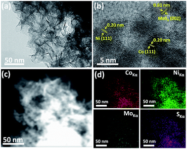 | ||
| Fig. 1 SEM image (a), HRTEM image (b), STEM image (c) and HAADF-STEM element mappings images (d) of the Co–Ni/MoS2 nanocomposite. | ||
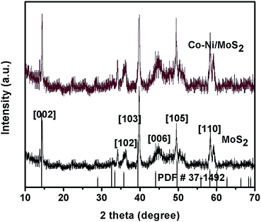
The XRD patterns of as-synthesized MoS2 and Co–Ni–MoS2 are shown in Fig. 2. The XRD pattern of the MoS2 nanosheets shows diffraction peaks which can be readily indexed to hexagonal MoS2 (JCPDS #37-1492) with cell parameters of a = 3.1612 Å, b = 3.1612 Å, c = 12.299 Å and space group P63/mmc.25 The characteristic XRD diffraction peaks of MoS2 were easily observed at 14.3°, 35.8°, 39.5°, 44.1°, 49.7° and 58.3° well matched to the [002], [102], [103], [006], [105] and [110] planes of the molybdenite-2H phase, respectively. The diffraction peaks of the Co and Ni nanoparticles in Co–Ni–MoS2 were not observed largely due to the ultra small size of the nanoparticles.
X-ray photoelectron spectroscopy (XPS) was used to evaluate the surface composition and valence states of Co–Ni–MoS2. The representative XPS survey scan spectrum (Fig. S1†) indicates the existence of the Mo, S, Co and Ni elements. Fig. 3a exhibits the Mo 3d binding energy (225–236 eV) region with binding energies for Mo 3d5/2 and Mo 3d3/2 of 229.5 and 232.3 eV, respectively, which can be readily assigned to Mo4+ which exists in the pure MoS2.26 Fig. 3b shows the high resolution XPS spectrum of S 2p which can be deconvoluted into two peaks, one at 161.3 and the other at 162.6 eV, attributed to S 2p3/2 and S 2p1/2 respectively, and these correspond well to the S2− of the 2H phase of MoS2. The binding energies of Co 2p3/2 and Co 2p1/2 are observed at 778.27 eV and 794.5 eV with satellite peaks at 782.0 eV and 799.0 eV, respectively, and are in good agreement with the values reported for Co nanoparticles with the presence of surface oxides, indicating the successful loading of Co nanoparticles (Fig. 3c).27 The high resolution XPS spectrum of the Ni 2p orbital shows two strong peaks at 852.67 eV and 870.7 eV, corresponding to Ni 2p3/2 and Ni 2p1/2, respectively (Fig. 3d). Ni 2p also shows satellite peaks at 857.47 eV and 875.9 eV which are in good agreement to those of Ni nanoparticles.28 The ratio of Co and Ni was observed to be 1![[thin space (1/6-em)]](https://www.rsc.org/images/entities/char_2009.gif) :
:![[thin space (1/6-em)]](https://www.rsc.org/images/entities/char_2009.gif) 1 from the XPS and ICP-AES measurements, which is in agreement with the experimental data.
1 from the XPS and ICP-AES measurements, which is in agreement with the experimental data.
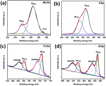 | ||
| Fig. 3 XPS spectra of Co–Ni/MoS2 nanocomposite: Mo 3d orbital (a), S 2p orbital (b), Co 2p orbital (c) and Ni 2p orbital (d). | ||
Among various transition metal sulfides, MoS2 has proved to be an efficient and active material for the electrocatalytic hydrogen evolution reaction (HER).29–31 Its benefits include lower cost, higher chemical stability, activity and almost comparable characteristics to graphene, such as the covalent bonded S–Mo–S sheets in MoS2 being associated together by weak van der Waals forces and its tendency to easily peel into thin sheets.32,33 In addition, the electrocatalytic HER activity and stability of MoS2-based composites in acidic media also present a challenge in order to meet the higher durability and stability requirements of catalysts when they are exposed to electrolysis equipment in acidic environments.34,35 Herein, the overall MoS2 based composite is defined as a Co–Ni associated Co–Ni–MoS2 hybrid. The as-developed nanocomposite material has shown excellent HER performance with a durable nature in acidic conditions. It is also documented that superior hydrodesulfurization behavior (HDS) of catalyst materials may lead to them having an extraordinary HER catalysis performance, due to the close free energy of adsorbed atomic hydrogen with that of the Pt-group metals (i.e., ΔGH* ≈ 0), this property makes them auspicious for the HER.36–38
In our designed electrocatalyst, the MoS2 material was tuned with Co–Ni co-doping, yielding Co–MoS2 and Ni–MoS2 phases, where the promotion degree of MoS2 is accelerated by the adjacent Co and Ni sites.39,40 The HER performance of all of the synthesized materials is shown in Fig. 4a and is also compared with the well-known commercial Pt/C catalyst. As for the HER catalysis, the performance of the catalyst material shows a strong dependence on the hydrogen adsorption energy and kinetic energy barrier of the hydrogen evolution reaction pathway. In Co–Ni/MoS2, the introduction of foreign metal candidates inside the MoS2 lattice induces the feasibility to engineer the electronic and/or surface structures for enhancing the HER activity. In light of the above stated factors, Co–Ni/MoS2 was shown to have a superior HER performance to that of Co–MoS2 and Ni–MoS2, in a systematic way. The performance of the Co–Ni/MoS2 nanocomposite has also proven that it has the potential to be an alternative catalyst to the commercial Pt/C catalyst. The enhanced HER activity may also correlate to morphology changes and/or chemical changes, through the introduction of bimetallic Co–Ni active sites with sulfur bridging.41,42
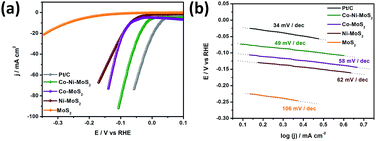 | ||
| Fig. 4 LSV curves in 0.1 M HClO4 (a) and Tafel plots (b) of MoS2, Ni/MoS2, Co/MoS2 and the Co–Ni/MoS2 nanocomposite. | ||
Remarkably, the Co–Ni/MoS2 catalyst showed a much smaller and highly improved HER onset potential than those of Co–MoS2 and Ni–MoS2, and a further increase in the overpotential led to an increase in the current density, even compared to that of the commercial Pt/C catalyst, as the cathodic current increased. The as-generated larger cathodic current compared to that of Pt/C should exclusively be due to two proposed reasons. First, from the catalytic reduction of protons from the Co–Ni co-associated MoS2 composite, and second, that the Co–MoS and Ni–MoS phases might play a more crucial role in decreasing the hydrogen binding energy (ΔGH) at the S-edge to weaken the H* adsorption tendency significantly.43,44 Cobalt and nickel are also considered to enhance the intrinsic activity of each active site by electron transfer towards molybdenum in the Co–Ni/MoS2 nanocomposite. This corresponds to the removal of σ* metal d – sulfur 3p electrons from Co–Ni resulting in a high intrinsic activity of these elements. The co-presence of Co–Ni also increases the dispersion degree owing to the stronger interaction between the metallic nanoparticles and support, enhancing the active sites. Moreover, the Tafel plots presented in Fig. 4b show a small Tafel slope of ca. 49 mV per decade for the as-developed Co–Ni/MoS2 nanocomposite which much better than those of Co–MoS2, Ni–MoS2 and MoS2 with values of ca. 58 mV per decade, 62 mV per decade, 106 mV per decade, respectively. The value is also very close to that of the Pt/C catalyst which has a 34 mV per decade characteristic slope value. The performance and Tafel values reflect classical HER theoretical behaviour in acidic media, and the Volmer–Heyrovsky HER mechanism should be responsible for the electrochemical HER by the Co–Ni–MoS2 nanocomposite and bare MoS2.45–47 Moreover, details on the specific calculated values for the HER performance for all of the catalysts have been provided in Table S1.†
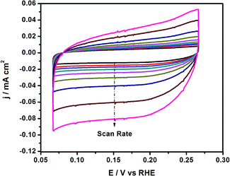
To better understand the enhanced HER performance of the Co–Ni/MoS2 catalyst, cyclic voltammetry was performed to evaluate the effective active surface area (Aeff). Cyclic voltammetry at various scan rates such as 1, 5, 10, 20, 40, 60, 80 and 100 mV s−1, etc. were performed within the range of 0.075–0.275 V vs. RHE, as presented in Fig. 5. From the as-driven cyclic voltammograms, the Aeff can be calculated by plotting the ΔJ at 0.15 V vs. RHE in the CV against the scan rate, where the slope is twice that of the Aeff.43 The measured Aeff value for Co–Ni–MoS2 is 6.3. In addition, the double layer capacitance (Cdl) behavior may also be predicted from the as-obtained CV results. Cdl values are directly related or proportional to the active surface area of the present catalyst material. The higher electrochemically active surface area positively contributes to the electrocatalytic HER activity.48 The overall results revealed that the Co–Ni co-association with the S-edge of the MoS2 structures may create more active sites, which are more effective for electrochemical performance than those of the bare MoS2, monoatomic Co/MoS2 and Ni/MoS2 catalysts.49,50 Moreover, the exposed surface area of MoS2 and active site density also play important roles in providing a large amount of active sites, and in turn, enhancing the activity.51
Similarly, the Aeff for Ni–MoS2 and Co–MoS2 have also been measured as 5.6 and 4.9, respectively, by using the CV segments presented in Fig. S2 and S3.†
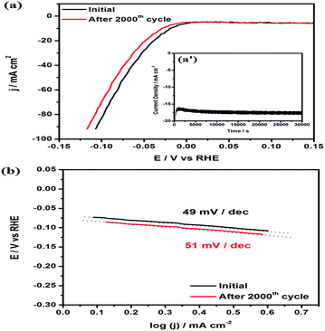
The durability and stability of the electrocatalyst is also an important and challenging task for the HER in acidic environments due to the occurrence of hydrogen evolution on the catalyst surface. The Co–Ni/MoS2 catalyst was subjected to accelerated durability tests (ADTs) and cycled between 0 V and −0.4 V at a scan rate of ca. 5 mV s−1 up to 2000 cycles to evaluate its long-term stability. As shown in Fig. 6a, long term durability tests were also conducted to examine the durable nature of the catalyst and stability of the catalyst material, the i–t curve results are shown as the inset Fig. 6a′. The i–t curves revealed an excellent durable performance and also gave a strong message of negligible or no dessolution of Ni and its constituted candidates within the whole catalyst material. After the ADTs test, the durability, in terms of Tafel slope behavior, were calculated and presented in Fig. 6b. From the results, it has been evaluated that the high performance material showed a ∼2–4% loss in its overall performance, including overpotential and Tafel slope. This loss in performance is very minor or negligible. Moreover, the shape of the particles also remains the same which suggests the high stability of Co–Ni/MoS2 under the reaction conditions (Fig. S4 and S5†). The ratio of Co–Ni was measured to be 1![[thin space (1/6-em)]](https://www.rsc.org/images/entities/char_2009.gif) :
:![[thin space (1/6-em)]](https://www.rsc.org/images/entities/char_2009.gif) 0.92 from ICP-AES measurements, which suggests the dissolution of a small amount of Ni during the ADTs. The XRD pattern of Co–Ni/MoS2 also remains the same after the ADTs which also suggests the stability of the as-synthesized material.
0.92 from ICP-AES measurements, which suggests the dissolution of a small amount of Ni during the ADTs. The XRD pattern of Co–Ni/MoS2 also remains the same after the ADTs which also suggests the stability of the as-synthesized material.
Apart from the visible ex situ electrochemical behavior of the HER, the electrode kinetics, interface reactions and electron transportation within the catalyst materials and inside the catalytic system, such as between the MoS2 & Co–Ni interfaces and the as-developed material and electrolyte interface, respectively, during the HER process, were characterized using electrochemical impedance spectroscopy. It can be seen from Fig. 7 that the derived Nyquist plots show that the Co–Ni/MoS2 nanocomposite has smaller resistance values in charge transfer (Rct) than those of MoS2, Co/MoS2 and Ni/MoS2, which would suggest a faster faradaic process and enhanced HER kinetics of the Co–Ni/MoS2 nanocomposite over other materials. The smaller Rct value may be attributed to the intrinsic modulation in the electronic structure induced by the association with Co–Ni metals.52,53
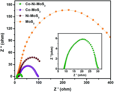 | ||
| Fig. 7 Nyquist plots of the electrochemical impedance spectroscopy (EIS) for MoS2, Co/MoS2, Ni/MoS2 and the Co–Ni/MoS2 nanocomposite. | ||
Conclusions
In conclusion, we have successfully synthesized a noble-metal-free Co–Ni/MoS2 nanocomposite and characterized it well from TEM, HRTEM, Elemental mapping, XRD and XPS analysis. The Co–Ni/MoS2 nanocomposite showed an enhanced performance for the electrocatalytic hydrogen evolution reaction comparable to that of commercial Pt/C. The Co–Ni/MoS2 nanocomposite showed a Tafel value of 49 mV per decade and an increased current density. The synergistic effect of Co–Ni nanoparticles with the MoS2 nanosheets greatly favors the hydrogen evolution performance. Moreover, the electrochemical impedance spectroscopic results suggest smaller resistance values in the Co–Ni/MoS2 nanocomposite which increase the charge mobility and in turn enhance the HER performance. Our as-synthesized noble-metal-free Co–Ni/MoS2 nanocomposite may hold great potential for the synthesis of future catalysts.Conflicts of interest
The authors declare no competing financial interest.Acknowledgements
The authors acknowledge financial support from the Qatar National Research Fund (A Member of The Qatar Foundation) NPRP grant #9-219-2-105. This work is also supported by the CAS-TWAS Presidents Fellowship Programme, USTC and Anhui Government Scholarship programmes. The statements made herein are solely the responsibility of the authors.References
- J. A. Turner, Science, 2004, 305, 972–974 CrossRef PubMed.
- J. W. Sun, D. K. Zhong and D. R. Gamelin, Energy Environ. Sci., 2010, 3, 1252–1261 CAS.
- E. Antolini, Energy Environ. Sci., 2009, 2, 915–931 Search PubMed.
- X. Zou and Y. Zhang, Chem. Soc. Rev., 2015, 44, 5148–5180 RSC.
- M. G. Walter, E. L. Warren, J. R. McKone, S. W. Boettcher, Q. Mi, E. A. Santori and N. S. Lewis, Chem. Rev., 2010, 110, 6446–6473 CrossRef CAS PubMed.
- H. B. Gray, Nat. Chem., 2009, 1, 7 CrossRef CAS PubMed.
- F. Jiao and H. Frei, Energy Environ. Sci., 2010, 3, 1018–1027 CAS.
- D. Merki and X. L. Hu, Energy Environ. Sci., 2011, 4, 3878–3888 CAS.
- A. B. Laursen, S. Kegnaes, S. Dahl and I. Chorkendorff, Energy Environ. Sci., 2012, 5, 5577–5591 CAS.
- T. F. Jaramillo, K. P. Jorgensen, J. Bonde, J. H. Nielsen, S. Horch and I. Chorkendorff, Science, 2007, 317, 100–102 CrossRef CAS PubMed.
- X. Huang, Z. Y. Zeng and H. Zhang, Chem. Soc. Rev., 2013, 42, 1934–1946 RSC.
- M. Chhowalla, H. S. Shin, G. Eda, L. J. Li, K. P. Loh and H. Zhang, Nat. Chem., 2013, 5, 263–275 CrossRef PubMed.
- W. Z. Wu, L. Wang, Y. L. Li, F. Zhang, L. Lin, S. M. Niu, D. Chenet, X. Zhang and Y. F. Hao, et al., Nature, 2014, 514, 470–474 CrossRef CAS PubMed.
- Q. H. Wang, K. K. Zadeh, A. Kis, J. N. Coleman and M. S. Strano, Nat. Nanotechnol., 2012, 7, 699–712 CrossRef CAS PubMed.
- W. F. Chen, K. Sasaki, C. Ma, A. I. Frenkel, N. Marinkovic, J. T. Muckerman, Y. M. Zhu and R. R. Adzic, Angew. Chem., Int. Ed., 2012, 51, 6131–6135 CrossRef CAS PubMed.
- M. Khan, A. B. Yousaf, M. Chen, C. Wei, X. Wu, N. Huang, Z. Qi and L. Li, Nano Res., 2016, 9, 837–848 CrossRef CAS.
- E. J. Popczun, J. R. McKone, C. G. Read, A. J. Biacchi, A. M. Wiltrout, N. S. Lewis and R. E. Schaak, J. Am. Chem. Soc., 2013, 135, 9267–9270 CrossRef CAS PubMed.
- H. F. Liang, A. N. Gandi, C. Xia, M. N. Hedhili, D. H. Anjum, U. Schwingenschlögl and H. N. Alshareef, ACS Energy Lett., 2017, 2, 1035–1042 CrossRef.
- B. M. Hunter, W. Hieringer, J. R. Winkler, H. B. Gray and A. M. Muller, Energy Environ. Sci., 2016, 9, 1734–1743 CAS.
- M. Gong, W. Zhou, M. C. Tsai, J. G. Zhou, M. Y. Guan, M. C. Lin, B. Zhang, Y. F. Hu, D. Y. Wang, J. Yang, S. J. Pennycook, B. J. Hwang and H. J. Dai, Nat. Commun., 2014, 5, 4695 CrossRef CAS PubMed.
- D. Kong, J. Cha, H. Wang, H. R. Lee and Y. Cui, Energy Environ. Sci., 2013, 6, 3553–3558 CAS.
- D. Kong, H. Wang, Z. Lu and Y. Cui, J. Am. Chem. Soc., 2014, 136, 4897–4900 CrossRef CAS PubMed.
- Q. Liu, J. Tian, W. Cui, P. Jiang, N. Cheng, A. M. Asiri and X. Sun, Angew. Chem., Int. Ed., 2014, 53, 6710–6714 CrossRef CAS PubMed.
- B. Cao, G. M. Veith, J. C. Neuefeind, R. R. Adzic and P. G. Khalifah, J. Am. Chem. Soc., 2013, 135, 19186–19192 CrossRef PubMed.
- Z. Wang, L. Ma, W. X. Chen, G. C. Huang, D. Y. Chen, L. B. Wang and J. Y. Yang Lee, RSC Adv., 2013, 3, 21675–21684 RSC.
- C. X. Lu, W. W. Liu, H. Li and B. K. Tay, Chem. Commun., 2014, 50, 3338–3340 RSC.
- Y. J. Yao, C. Xu, J. C. Qin, F. Y. Wei, M. N. Rao and S. B. Wang, Ind. Eng. Chem. Res., 2013, 52, 17341–17350 CrossRef CAS.
- Q. Guo, D. Liu, X. Zhang, L. Li, H. Hou, O. Niwa and T. You, Anal. Chem., 2014, 17, 5898–5905 CrossRef PubMed.
- B. Hinnemann, P. G. Moses, J. Bonde, K. P. Jørgensen, J. H. Nielsen, S. Horch, I. Chorkendorff and J. K. Nørskov, J. Am. Chem. Soc., 2005, 127, 5308–5309 CrossRef CAS PubMed.
- Y. Li, H. Wang, L. Xie, Y. Liang, G. Hong and H. Dai, J. Am. Chem. Soc., 2011, 133, 7296–7299 CrossRef CAS PubMed.
- H. Wang, Z. Lu, D. Kong, J. Sun, T. M. Hymel and Y. Cui, ACS Nano, 2014, 8, 4940–4947 CrossRef CAS PubMed.
- R. D. Nikam, A. Y. Lu, P. A. Sonawane, U. R. Kumar, K. Yadav and L. J. Li, et al., ACS Appl. Mater. Interfaces, 2015, 7, 23328–23335 CAS.
- Z. C. Xiang, Z. Zhang, X. J. Xu, Q. Zhang and C. Yuan, Carbon, 2015, 98, 84–89 CrossRef.
- N. Bai, Q. Li, D. Mao, D. Li and H. Dong, ACS Appl. Mater. Interfaces, 2016, 8, 29400–29407 CAS.
- Z. Xing, X. Yang, A. M. Asiri and X. Sun, ACS Appl. Mater. Interfaces, 2016, 8, 4521–4526 Search PubMed.
- B. Hinnemann, P. G. Moses, J. Bonde, K. P. Jorgensen, J. H. Nielsen, S. Horch, I. Chorkendorff and J. K. Norskov, J. Am. Chem. Soc., 2005, 127, 5308–5309 CrossRef CAS PubMed.
- T. F. Jaramillo, K. P. Jorgensen, J. Bonde, J. H. Nielsen, S. Horch and I. Chorkendorff, Science, 2007, 317, 100–102 CrossRef CAS PubMed.
- C. G. Morales-Guio and X. L. Hu, Acc. Chem. Res., 2014, 47, 2671–2681 CrossRef CAS PubMed.
- T. K. T. Ninh, L. Massin, D. Laurenti and M. A. Vrinat, Appl. Catal., A, 2011, 407, 29–39 CrossRef CAS.
- F. Rashidi, T. Sasaki, A. M. Rashidi, A. N. Kharat and K. J. Jozani, J. Catal., 2013, 299, 321–335 CrossRef CAS.
- J. Bonde, P. G. Moses, T. F. Jaramillo, J. K. Nørskov and I. Chorkendorff, Faraday Discuss., 2009, 140, 219–231 RSC.
- D. Merki, H. Vrubel, L. Rovelli, S. Fierro and X. L. Hu, Chem. Sci., 2012, 3, 2515–2525 RSC.
- K. Zhang, H. J. Kim, J. T. Lee, G. W. Chang, X. J. Shi, W. J. Kim, M. Ma, K. J. Kong, J. M. Choi, M. S. Song and J. H. Park, ChemSusChem, 2014, 7, 2489–2495 CrossRef CAS PubMed.
- J. Greeley, T. F. Jaramillo, J. Bonde, I. Chorkendorff and J. K. Nørskov, Nat. Mater., 2006, 5, 909–913 CrossRef CAS PubMed.
- J. F. Xie, H. Zhang, S. Li, R. X. Wang, X. Sun, M. Zhou, J. F. Zhou, X. W. Lou and Y. Xie, Adv. Mater., 2013, 25, 5807 CrossRef CAS PubMed.
- Y. Yan, X. M. Ge, Z. L. Liu, J. Y. Wang, J. M. Lee and X. Wang, Nanoscale, 2013, 5, 7768 RSC.
- Z. Z. Wu, C. Y. Tang, P. Zhou, Z. H. Liu, Y. S. Xu, D. Z. Wang and B. Z. Fang, J. Mater. Chem. A, 2015, 3, 13050–13056 CAS.
- X. C. Yin, H. F. Dong, G. Sun, W. Yang, A. L. Song, Q. H. Du, L. Su and G. J. Shao, International Journal of Hydrogen Energy, 2017, 42, 11262–11269 CrossRef CAS.
- X. P. Dai, K. L. Du, Z. Z. Li, M. Z. Liu, Y. D. Ma, H. Sun, X. Zhang and Y. Yang, ACS Appl. Mater. Interfaces, 2015, 7, 27242–27253 CAS.
- D. Z. Wang, D. Z. Zhang, C. Y. Tang, P. Zhou, Z. Z. Wu and B. Z. Fang, Catal. Sci. Technol., 2016, 6, 1952–1956 Search PubMed.
- Z. Z. Wu, B. Z. Fang, Z. P. Wang, C. L. Wang, Z. H. Liu, F. Y. Liu, W. Wang, A. Alfantazi, D. Z. Wang and D. P. Wilkinson, ACS Catal., 2013, 3, 2101–2107 CrossRef CAS.
- J. Deng, H. B. Li, J. P. Xiao, Y. C. Tu, D. H. Deng, H. X. Yang, H. F. Tian, J. Q. Li, P. J. Ren and X. H. Bao, Energy Environ. Sci., 2015, 8, 1594 CAS.
- H. T. Wang, C. Tsai, D. S. Kong, K. R. Chan, F. Abild-Pedersen, J. Norskov and Y. Cui, Nano Res., 2015, 8, 566 CrossRef CAS.
Footnotes |
| † Electronic supplementary information (ESI) available: Survey XPS spectrum of Co–Ni–MoS2, cyclic voltammetry at various scan rates for Co–MoS2 and Ni–MoS2, TEM images and XRD pattern of Co–Ni/MoS2 after accelerated durability tests (ADTs). See DOI: 10.1039/c7ra12692a |
| ‡ These two authors contributed equally to this work. |
| This journal is © The Royal Society of Chemistry 2018 |

