 Open Access Article
Creative Commons Attribution 3.0 Unported Licence
Experimental study on the durability of the polydopamine functionalized gas–liquid–solid microreactor for nitrobenzene hydrogenation
Xun Zhu *ab,
Hao Fengab,
Rong Chenab,
Qiang Liaoab,
Dingding Yeab,
Biao Zhangab,
Jian Liuab,
Ming Liuab and
Gang Chenab
aKey Laboratory of Low-Grade Energy Utilization Technologies and Systems (Chongqing University), Ministry of Education, Chongqing 400030, China. E-mail: zhuxun@cqu.edu.cn; Fax: +86-23-65102474; Tel: +86-23-65102474
bInstitute of Engineering Thermophysics, Chongqing University, Chongqing 400030, China
First published on 2nd February 2018
Abstract
As a promising technique for multiphase catalytic reactions, the widespread applications of gas–liquid–solid microreactors are still limited by poor durability. Hence, in this work, a method for the preparation of Pd nanocatalysts inside a gas–liquid–solid microreactor was proposed to realize long-term durability using electroless deposition on the polydopamine functionalized surface followed by hydrogen reduction. This method not only increases the utilization efficiency of the Pd ions but also improves the durability of the microreactor. The chemical composition and topography characterization of the fabricated catalyst layer were tested using XPS and FESEM, respectively. The results indicated that the incorporation of hydrogen reduction resulted in nearly all palladium ions being reduced and the palladium nanoparticles were dispersed uniformly on the polydopamine modified surface. The microreactor prepared by this method exhibited high durability and high nitrobenzene conversion as compared to the traditional electroless catalyst deposition. Besides, it was shown that the increased inlet nitrobenzene concentration and flow rates played a negative role in the durability. The longer microreactor exhibited a better durability.
1. Introduction
Multiphase catalytic reactions, such as catalytic cracking, catalytic reforming, catalytic hydrogenation, etc., have been widely used in the chemical and pharmaceutical industries.1–4 In these applications, to reduce the potential mass transfer resistance between the phases and improve the reaction rate, the pressure or/and temperature are usually increased, which will increase not only the explosion potential but also the processing and manufacturing costs.5 Microreactors have an intrinsically large interfacial area per unit volume and have proven to be able to dramatically enhance heat and mass transfer as well as reduce the explosion potential, making them suitable for multiphase catalytic reactions.6–11To date, numerous studies have been carried out to investigate the microreactor technologies for various catalytic reactions, such as the catalytic oxidation,12 the catalytic hydrogenation,6 the catalytic combustion,13 etc. It has been found that the property of the prepared catalyst layer inside the microreactor is crucial to affect the microreactor performance. Therefore, a variety of attempts have been made to prepare the catalyst layer.14,15 Metal nanoparticles that exhibit high catalytic activity, such as nickel, copper, palladium, platinum, etc., have been chosen as the catalysts towards various catalytic reactions by sputtering, impregnation and sol–gel methods, etc.16–18 Generally, catalysts prepared by these methods could guarantee high activity. However, the calcination process during the fabrication is typically required to improve the adhesion with the substrate, which not only increases the manufacturing cost and potential risk but also limits the selection of materials. In addition to the catalytic activity, the durability of the fabricated catalyst layer is another key issue, which directly affects the industrial applications of the microreactor technologies. Unfortunately, the durability of the existing catalyst layers inside the microreactor fabricated by the conventional methods is still poor.17,18 Therefore, facile methods are needed for preparing catalyst layer with good durability and activity in the microreactors.
To address the above-mentioned issues, extensive efforts have been devoted to this area. For example, Kobayashi et al.6 immobilized the polymer encapsulated Pd nanoparticles inside the glass-fabricated microreactor. Hornung et al.19–21 deposited the metal nanoparticles on the polyelectrolyte using layer by layer self-assembly technology. Although significant progress has been made, there still exist problems of relatively low activity or substrate selectivity to the catalyst. Previous studies22,23 have indicated that adhesive proteins secreted by mussels are able to attach onto virtually various substrates, including organic and inorganic materials. Inspired by the adhesive proteins in mussels, Lee et al.24–26 used the self-polymerization of dopamine to form thin polydopamine film on various substrates, and demonstrated that the fabricated polydopamine film was excellent for the electroless deposition, which provided a new, facile method for nanocatalysts deposition on both conductive and insulated substrates. After that, successful immobilizations of metal nanoparticles on the functionalized polydopamine surface have been reported.27–29 However, the electroless deposition of metal nanoparticles on the functionalized polydopamine surface still faces a problem, that is, there remains a large amount of residual metal ions on the polydopamine surface as a result of the limited reduction ability of polydopamine. Incomplete reduction not only decreases the utilization efficiency of the metal ions but also results in fast deactivation of the nanocatalysts and thus reduces reactant conversion and the durability of the microreactor. To solve this problem, a gas–liquid–solid microreactor was developed with the polydopamine functionalized surface coated with highly-active palladium nanocatalysts by the electroless deposition plus using hydrogen as a reducing agent.30 The experimental results showed the developed gas–liquid–solid microreactor was able to yield good catalytic activity. However, as one of the key points reflecting the performance of the microreactor, the durability of the microreactor fabricated by this method remains unknown. For this reason, particular attention of this work was paid to the evaluation of the durability of the gas–liquid–solid microreactor fabricated by this method under various operation conditions. For comparison, the differences in the chemical composition and morphology as well as the performance between the catalyst layer without and with further hydrogen reduction under different operational conditions were studied.
2. Experimental
2.1 Materials and chemicals
Commercially available PTFE (polytetrafluoroethylene) tube with the inner diameter of 0.6 mm and outer diameter of 1.0 mm was used to fabricate the microreactor. Dopamine hydrochloride and Tris (tris(hydroxymethyl) aminomethane) were purchased from Aladdin Industrial Inc (Shanghai, China) and GEN-VIEW Scientific Inc (Florida, USA), respectively. Palladium chloride was obtained from Sino-Platinum Metals Co. Ltd (Kunming, China). Potassium chloride, ethanol, nitrobenzene were acquired from Chongqing Chuandong Chemical Co. Ltd (Chongqing, China). The chemicals were analytical reagent grade and used as-received. Deionized water was obtained from an Ultrapure Water System for Laboratory (ROMB, China).2.2 Dopamine self-polymerization on the inner surface of PTFE tube
Alkaline dopamine aqueous solution was prepared by dissolving dopamine in 10 mM Tris buffer solution with the dopamine concentration of 2 mg mL−1. In order to form an adherent polydopamine layer on the inner surface of the PTFE tube, the prepared dopamine aqueous solution was firstly introduced into the PTFE tube at a flow rate of 1 mL h−1 for 5 h using a syringe pump (LSP04-1A, Longer-Pump, China). In the following, the PTFE tube was flushed with 10 mL deionized water at a flow rate of 0.5 mL min−1. Then, nitrogen gas was continuously fed into the tube at a flow rate of 2 sccm and heated at 338 K for 1 h by a mass flow controller (FMA-2616A-I, Omega, USA) and an electric heating plate (OMHP-3C, OU-mai, China), respectively. After the completion of these steps, a polydopamine film on the inner wall of the PTFE tube could be acquired. The obtained modified PTFE tube was denoted as PDA/PTFE.2.3 Electroless deposition of palladium nanoparticles on PDA modified surface
In this stage, 5 mM K2PdCl4 aqueous solution prepared by dissolving PdCl2 and KCl in water (PdCl2: 886.65 μg mL−1 and KCl: 372.75 μg mL−1), was used as the precursor solution. The precursor solution was infiltrated into the PTFE tube with coated PDA layer at a flow rate of 50 μL min−1. Once the tube was full of the precursor solution, the flow rate of the precursor solution was then changed to 0.1 μL min−1 and maintained for 12 h to adsorb and reduce the Pd ions. After that, excess amount of water was fed into the PTFE tube several times at a flow rate of 10 μL min−1 to the remove of residual ions, which was followed by flushing with nitrogen gas at a flow rate of 0.1 sccm for 5–10 min to remove the remaining water. Finally, the resulting PTFE tube was placed into a vacuum tube resistance furnace (Tianjin Zhonghuan Lab Furnace Co., Ltd, China) and heated in the H2 environment under 473 K for 4 h to further reduce the residual Pd ions to metallic nanoparticles. The obtained sample was denoted as Pd-PDA/PTFE in the following discussion. To estimate the Pd content in the microreactor, a UV-visible spectrophotometer (T6-1650E, Persee, China) with the wavelength range from 190 nm to 1100 nm at 1 nm resolution was used to measure the difference between the 5 mM K2PdCl4 solution and the collected K2PdCl4 solution after deposition. The result is shown in Fig. 1. As can be seen, the solutions before and after the deposition both showed a peak at 416 nm in the UV-vis spectrum, which corresponded to palladium ions.31 The absorbance decreased from 1.62 to 0.86 after the deposition, indicating that the concentration of the palladium ions in the collected K2PdCl4 solution was about 2.65 mM. Considering that about 360 μL 5 mM K2PdCl4 solution was introduced into the microreactor for the Pd deposition, the content of Pd catalyst in the microreactor was thus estimated to be about 90 μg (4.77 μg cm−2).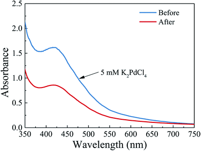 | ||
| Fig. 1 UV-vis spectra of the K2PdCl4 solution before and after the electroless deposition on the polydopamine functionalized surface. | ||
2.4 Materials characterization and experimental setup
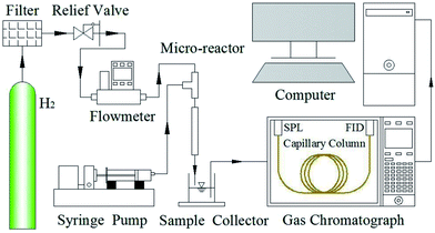
The chemical compositions of original and modified PTFE, Pd-PDA/PTFE were determined by XPS using an ESCALAB 250Xi XPS system (Thermo, USA) with Al Kα radiation (hν = 1486.6 eV) at a reduced power of 150 W. The surface morphologies of these samples were characterized by using a field emission scanning electron microscope (S4800, Hitachi High Technologies, Japan) with the accelerating voltage of 3 kV. Fig. 2 shows the schematic diagram of the experimental system. To supply the gaseous and liquid reactants stably and continuously, the liquid reactant prepared by dissolving nitrobenzene in ethanol aqueous solution (C2H5OH![[thin space (1/6-em)]](https://www.rsc.org/images/entities/char_2009.gif) :
:![[thin space (1/6-em)]](https://www.rsc.org/images/entities/char_2009.gif) H2O = 7
H2O = 7![[thin space (1/6-em)]](https://www.rsc.org/images/entities/char_2009.gif) :
:![[thin space (1/6-em)]](https://www.rsc.org/images/entities/char_2009.gif) 3, v/v), and the gaseous reactant of high-purity hydrogen were simultaneously fed into the microreactor using a syringe pump (LSP01-1BH, Longer-Pump, China) and a mass flow controller (FMA-2602A-I, Omega, USA) through a home-made connector. The effluent was collected and measured by a gas chromatograph (GC-2010 Plus, Shimadzu, Japan) equipped with a split/splitless injection unit (SPL), a capillary column (Rtx-1301, 30 m × 0.32 mm, Restek, USA) and a flame ionization detector (FID) to measure the concentration of nitrobenzene and the desired product of aniline.
3, v/v), and the gaseous reactant of high-purity hydrogen were simultaneously fed into the microreactor using a syringe pump (LSP01-1BH, Longer-Pump, China) and a mass flow controller (FMA-2602A-I, Omega, USA) through a home-made connector. The effluent was collected and measured by a gas chromatograph (GC-2010 Plus, Shimadzu, Japan) equipped with a split/splitless injection unit (SPL), a capillary column (Rtx-1301, 30 m × 0.32 mm, Restek, USA) and a flame ionization detector (FID) to measure the concentration of nitrobenzene and the desired product of aniline.
3. Results and discussion
3.1 Characterization of dopamine self-polymerization
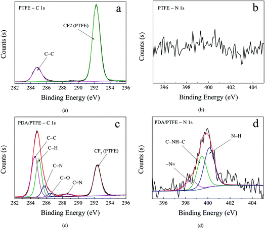
To elaborate the formation of the PDA layer, the chemical compositions of the original and PDA modified PTFE were characterized by XPS. Fig. 3 shows the narrow scan spectra and curve fitting of the C 1s and N 1s for the pristine and PDA modified PTFE. As can be seen in Fig. 3a, the C 1s core-level spectrum of the pristine PTFE tube can be curve-fitted into two peaks at 284.8 eV and 292.3 eV, which represented the C–C and CF2, respectively. As compared with the pristine PTFE, four additional peaks represented the C–H (285.0 eV), C–N (285.7 eV), C–O (286.5 eV), C![[double bond, length as m-dash]](https://www.rsc.org/images/entities/char_e001.gif) N (288.6 eV), respectively, existed in the PDA modified PTFE (see Fig. 3c). The appearance of C
N (288.6 eV), respectively, existed in the PDA modified PTFE (see Fig. 3c). The appearance of C![[double bond, length as m-dash]](https://www.rsc.org/images/entities/char_e001.gif) N in the PDA/PTFE was consistent with the structure of PDA, which indicated the existence of PDA. In order to further verify the composition of PDA on the inner wall of the PTFE tube, the N 1s spectrum was also curve-fitted. Compared with the pristine PTFE (see Fig. 3b), the N 1s of PDA/PTFE shown in Fig. 3d can be decomposed into three typical peaks assigned to –N
N in the PDA/PTFE was consistent with the structure of PDA, which indicated the existence of PDA. In order to further verify the composition of PDA on the inner wall of the PTFE tube, the N 1s spectrum was also curve-fitted. Compared with the pristine PTFE (see Fig. 3b), the N 1s of PDA/PTFE shown in Fig. 3d can be decomposed into three typical peaks assigned to –N![[double bond, length as m-dash]](https://www.rsc.org/images/entities/char_e001.gif) (398.5 eV), C–NH–C (399.5 eV) and N–H (400.1 eV). During the self-polymerization process of dopamine, the structure evolution of amine group in dopamine formed –N
(398.5 eV), C–NH–C (399.5 eV) and N–H (400.1 eV). During the self-polymerization process of dopamine, the structure evolution of amine group in dopamine formed –N![[double bond, length as m-dash]](https://www.rsc.org/images/entities/char_e001.gif) and C–NH–C, and the N–H was attributed to the amine group.32,33 The existence of –N
and C–NH–C, and the N–H was attributed to the amine group.32,33 The existence of –N![[double bond, length as m-dash]](https://www.rsc.org/images/entities/char_e001.gif) and C–NH–C was in accordance with the PDA structure, which also demonstrated the existence of PDA. In conclusion, the XPS results suggest that PDA layer has been successfully adhered to the inner surface of PTFE tube through the self-polymerization of dopamine.
and C–NH–C was in accordance with the PDA structure, which also demonstrated the existence of PDA. In conclusion, the XPS results suggest that PDA layer has been successfully adhered to the inner surface of PTFE tube through the self-polymerization of dopamine.
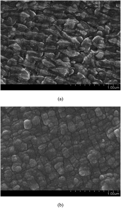
Fig. 4 shows the FESEM images of pristine PTFE and PDA/PTFE at different magnifications. As can be seen, prior to the PDA formation, the PTFE tube exhibited a striped surface microstructure. After coating the PDA on the PTFE surface, a cubic surface microstructure was observed. The difference in the surface morphology between the PTFE and the PDA/PTFE indicated a uniform PDA coating was formed on the inner surface of the PTFE tube.
3.2 Characterization of Pd nanoparticles on PDA/PTFE surface
In order to obtain the surface morphology and chemical structure of the PDA layer coated with palladium, FESEM and XPS measurements were performed. The XPS Pd 3d core-level spectrum for Pd nanoparticles only reduced by the PDA is presented in Fig. 5a. It was shown that the deconvolution of the Pd 3d core-level spectrum of the Pd-PDA layer resulted in four peaks at 335.4 eV, 337.2 eV, 340.7 eV and 342.7 eV, which were assigned to Pd0 (3d5/2), Pd–O– (3d5/2), Pd0 (3d3/2) and Pd–O– (3d3/2), respectively. The Pd0 component came from the reduction of Pd2+ to Pd0 since the existence of catechol and N-containing functional groups from the PDA layer, which acted not only as an adhesive but also as a reducing agent for the formation of Pd nanoparticles.27,32 In this deposition step, since catechol could serve as a good ligand to form chelates with palladium ions, palladium ions were able to bound with the anionic oxygen of the catechol contained in the PDA. However, due to the limited reduction ability of PDA, there always existed a large amount of Pd–O– components at the surface. As mentioned earlier, to further reduce the residual palladium ions on the PDA surface to metallic palladium nanoparticles and increase the precursor utilization efficiency, extra reducing agent of hydrogen gas was introduced in this work. Similarly, the XPS Pd 3d core-level spectrum for Pd nanoparticles after the hydrogen reduction was measured, and the result is shown in Fig. 5b. As shown, the Pd 3d spectrum always consists of Pd0 (3d5/2), Pd–O– (3d5/2), Pd0 (3d3/2) and Pd–O– (3d3/2). However, compared to the result without hydrogen reduction, the peak components associated with Pd–O– were much smaller, which indicated that most of the palladium ions have been successfully reduced and deposited on the PDA/PTFE surface in the metallic state.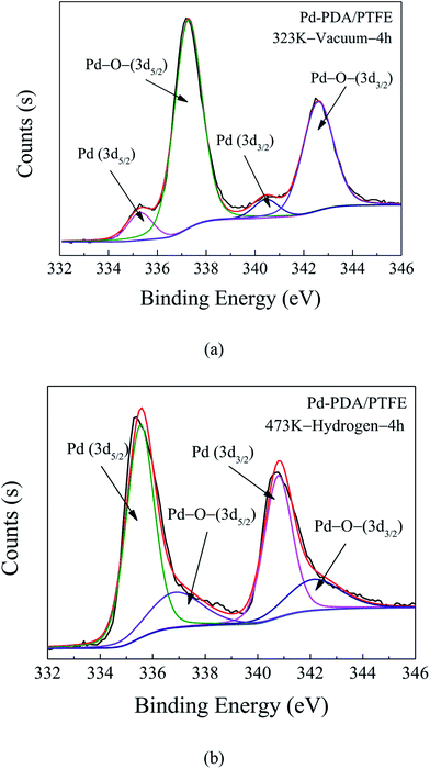 | ||
| Fig. 5 XPS Pd 3d core-level spectra of Pd-PDA/PTFE catalyst layer without (a) and with (b) hydrogen reduction. | ||
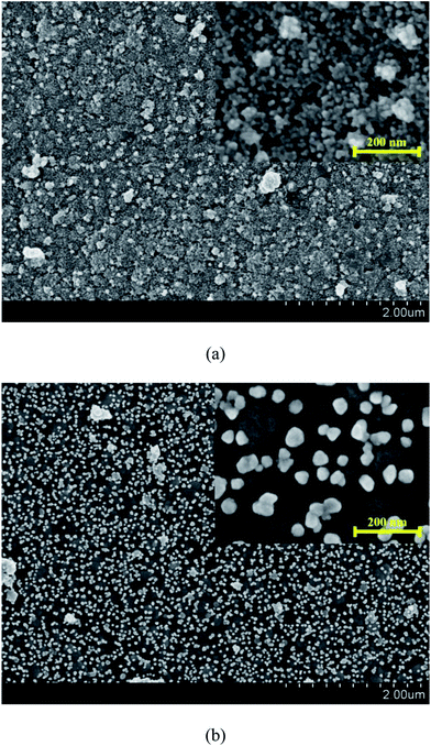
Fig. 6 shows the surface morphology of the Pd-PDA surfaces without and with hydrogen reduction. As can be seen in Fig. 6a, the size of the vast majority of the Pd nanoparticles lied in the range of about 15 nm, which were dispersed uniformly on the PDA surface. Fig. 6b shows the morphology result of the catalyst with the further reduction by hydrogen. As can be seen, the discrete Pd nanoparticles were well distributed on the PDA surface, but the particles sizes were larger than those without further hydrogen reduction. Two reasons contributed to this phenomenon. First, when the Pd ions adsorbed on the PDA surface uniformly, although they could be reduced by the PDA, the reduction ability of the PDA was weak. Hence, only a small part of the adsorbed Pd ions could be reduced to metallic state and the majority was still kept at ion state.32 In this case, the Pd nanoparticles were unable to exhibit large particle size. On the other hand, for the case with hydrogen reduction, nearly all adsorbed Pd ions could be reduced so that the Pd nanoparticles could grow bigger during the reduction process. Moreover, a high operation temperature of 473 K was required in this process. Such a high reduction temperature may lead to easy agglomeration of Pd nanoparticles to form larger particles.34 As a consequence, although almost all the Pd ions were reduced to elemental palladium with the further hydrogen reduction, the particle size was also increased.
3.3 Evaluation of durability
Durability, as one of the important indicators to evaluate the performance of the catalyst layer in the microreactor, plays a critical role in the industrial applications. Thus, a long-term operation was carried out for the durability characterizations of the catalyst layers with and without further hydrogen reduction. In this test, the inlet nitrobenzene concentration was kept at 60 mM, hydrogen and nitrobenzene flow rates were set at 0.15 sccm and 15 μL min−1, respectively. The variations of the nitrobenzene conversion with the operation time are shown in Fig. 7. As can be seen, for the catalyst layer without hydrogen reduction, during the first 3 h operation, the average nitrobenzene conversion could reach over 97%, but it was decreased to 50.5% with further increasing the operation time. However, for the catalyst layer with further reduction by hydrogen, over the entire operation period of 37 h, the nitrobenzene conversion could be kept stable during the first 28 h operation with an average nitrobenzene conversion of about 97% and then declined gradually to 60.03% in the next 9 h operation. These results indicated that the catalyst layer prepared with hydrogen reduction could not only perform an excellent catalytic activity for the hydrogenation of nitrobenzene but also showed much better durability than did the one without hydrogen reduction. Such a big gap in the catalyst durability may be attributed to the differences in the proportions of Pd metallic state. It is well known that the nitrobenzene hydrogenation is a structure insensitive catalytic reaction. Its reaction rate does not depend on the crystal surface structure of the active metal, but only relies on the amount of metallic Pd catalyst exposed to the reactants.35 For the catalyst layer without hydrogen reduction, a significant amount of Pd ions has not been completely reduced so that the Pd–O– species existed in the catalyst layer were unable to catalyze the nitrobenzene hydrogenation. However, there was still a small amount of the reduced Pd, which had good activity to the nitrobenzene hydrogenation. In this case, the catalyst layer with hydrogen reduction could exhibit good performance at the initial period of 3 hours. However, during the reaction process, the catalyst deactivation as a result of the catalyst poison, nanocatalysts agglomeration, etc., is unavoidable. The generated intermediates/by-products (such as nitrosobenzene, azoxybenzene) have a strong adsorption on the active sites of the Pd nanocatalysts and can directly poison the Pd nanocatalyst.36,37 As a result, for the catalyst layer without hydrogen reduction, although good performance could be obtained at the beginning, the durability was rather poor. However, for the catalyst layer with hydrogen reduction, almost all the Pd ions had been reduced and utilized, the Pd species exposed to the reactants was much more than those without hydrogen reduction. Besides, the Pd particle size was large, making it a little difficult to agglomerate during the operation. Hence, it could perform a much better durability for the nitrobenzene hydrogenation compared with the catalyst layer without hydrogen reduction. In addition, we also compared the catalytic performance and durability of the catalysts fabricated in this study with those conventional methods and the results are listed in Table 1. As shown, in comparison to the catalyst layer in the conventional microreactors and the catalyst in the batch reactor, the catalysts fabricated by the proposed method in this work exhibited not only high nitrobenzene conversion but also relatively good durability. It is further demonstrated that the method proposed in this study shows the promising potential for future industrial applications.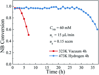 | ||
| Fig. 7 Variations of the nitrobenzene conversion with the reaction time between the catalyst layer with and without hydrogen reduction. | ||
| Catalyst | Reactor | CNB/mM | t/s | XNB | Durability/h | Ref. |
|---|---|---|---|---|---|---|
| a CNB – initial/inlet nitrobenzene concentration, XNB – nitrobenzene conversion, t – residence/reaction time. | ||||||
| Pd film | Micro | 400 | 17 | 27% | 1 | 16 |
| Pt/TiO2 | Micro | 50 | 12 | 93% | 8 | 17 |
| Pd/Al2O3 | Micro | 30 | 400 | 90% | 10 | 18 |
| Pt/CNT | Batch | 98 | 2400 | 90% | — | 35 |
| Pd/PDA | Micro | 60 | 112 | 97% | 28 | This work |
3.4 Effect of the operating parameters on durability
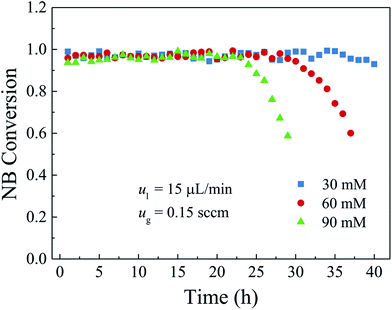
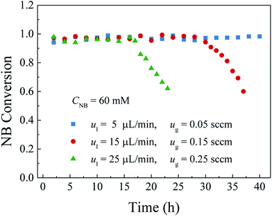
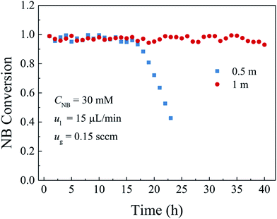
To further evaluate the durability of the fabricated catalyst layer, the effects of the inlet nitrobenzene concentration, the flow rate as well as the length of the microreactor were also investigated in this work.| Residence time = channel volume/gas flow rate |
4. Conclusions
A catalyst layer with high durability is of importance before the widespread applications of the gas–liquid–solid microreactors. In this study, a polydopamine functionalized gas–liquid–solid microreactor with the absorbed Pd ions further reduced by hydrogen to enhance the durability. The surface chemical composition of the catalyst layer fabricated by this method showed that the proportion of metallic Pd in catalyst layer reduced with hydrogen was much larger than that without additional hydrogen reduction. The morphology characterization indicated that Pd nanoparticles were well deposited and uniformly dispersed on the PDA modified surface with an average particles size of about 50 nm. The durability of the developed microreactor was evaluated by the nitrobenzene hydrogenation. It was shown that both high nitrobenzene conversion and durability were obtained for the developed microreactor. Besides, the effects of the inlet nitrobenzene concentration and the flow rates and the microreactor length on the durability were also investigated. The results showed that, for the given flow rates and microreactor length, the nitrobenzene conversion was kept stable without obvious decrease at the inlet nitrobenzene concentration of 30 mM over the entire operation period because of less adsorption of the intermediates and by-products on the active sites. When the nitrobenzene concentration was 60 mM, the nitrobenzene conversion was kept stable in the first 28 h and then gradually declined to 60% in the next 9 h. As the inlet nitrobenzene concentration was further increased to 90 mM, the durability of the microreactor was further decreased. As for the effect of the flow rates, a tendency that the durability of the microreactor was decreased with the increase of the flow rates could be obtained as a result of intensified adsorption of the intermediates and by-products on the active sites as well as the decreased residence time. Regarding the effect of the microreactor length, it was found that the durability of the microreactor increased with the microreactor length because of increased catalyst loading and residence time. The obtained results reveal that the developed gas–liquid–solid microreactor can not only yield high conversion but also promote the durability.Conflicts of interest
There are no conflicts to declare.Acknowledgements
The authors gratefully acknowledge the financial supports of the National Natural Science Foundation of China (No. 51325602 and No. 51620105011).References
- A. Moyano and R. Rios, Asymmetric organocatalytic cyclization and cycloaddition reactions, Chem. Rev., 2011, 111, 4703–4832 CrossRef CAS PubMed.
- S. McGovern, G. Harish, C. Pai, W. Mansfield, J. Taylor, S. Pau and R. Besser, Multiphase flow regimes for hydrogenation in a catalyst-trap microreactor, Chem. Eng. J., 2008, 135, S229–S236 CrossRef CAS.
- T. Yu, T. Yu, Q. Zhang, S. Xia, G. Li and C. Hu, Direct amination of benzene to aniline by reactive distillation method over copper doped hierarchical TS-1 catalyst, Catal. Sci. Technol., 2013, 4, 639–647 Search PubMed.
- L. Cheng, Q. Dai, H. Li and X. Wang, Highly selective hydrogenation of phenol and derivatives over Pd catalysts supported on SiO2 and γ-Al2O3 in aqueous media, Catal. Commun., 2014, 57, 23–28 CrossRef CAS.
- R. J. Alaimo, Handbook of chemical health and safety, American Chemical Society, Oxford University Press, Washington D.C., 2001 Search PubMed.
- J. Kobayashi, Y. Mori, K. Okamoto, R. Akiyama, M. Ueno, T. Kitamori and S. Kobayashi, A microfluidic device for conducting gas-liquid-solid hydrogenation reactions, Science, 2004, 304, 1305–1308 CrossRef CAS PubMed.
- A. J. DeMello, Control and detection of chemical reactions in microfluidic systems, Nature, 2006, 442, 394–402 CrossRef CAS PubMed.
- B. P. Mason, K. E. Price, J. L. Steinbacher, A. R. Bogdan and D. T. McQuade, Greener approaches to organic synthesis using microreactor technology, Chem. Rev., 2007, 107, 2300–2318 CrossRef CAS PubMed.
- B. Gutmann, D. Cantillo and C. O. Kappe, Continuous-flow technology – a tool for the safe manufacturing of active pharmaceutical ingredients, Angew. Chem., Int. Ed., 2015, 54, 6688–6728 CrossRef CAS PubMed.
- K. S. Elvira, X. C. i Solvas, R. C. Wootton and A. J. deMello, The past, present and potential for microfluidic reactor technology in chemical synthesis, Nat. Chem., 2013, 5, 905–915 CrossRef CAS PubMed.
- J. Zhang, C. Gong, X. Zeng and J. Xie, Continuous flow chemistry: new strategies for preparative inorganic chemistry, Coord. Chem. Rev., 2016, 324, 39–53 CrossRef CAS.
- C. Shen, Y. J. Wang, J. H. Xu and G. S. Luo, Glass capillaries with TiO2 supported on inner wall as microchannel reactors, Chem. Eng. J., 2015, 277, 48–55 CrossRef CAS.
- J. A. Federici and D. G. Vlachos, Experimental studies on syngas catalytic combustion on Pt/Al2O3 in a microreactor, Combust. Flame, 2011, 158, 2540–2543 CrossRef CAS.
- L. Li, R. Chen, X. Zhu, Q. Liao, H. Wang, L. An and M. X. Zhang, A cascading gradient pore microstructured photoanode with enhanced photoelectrochemical and photocatalytic activities, J. Catal., 2016, 344, 411–419 CrossRef CAS.
- G. Guan, K. Kusakabe, M. Taneda, M. Uehara and H. Maeda, Catalytic combustion of methane over Pd-based catalyst supported on a macroporous alumina layer in a microchannel reactor, Chem. Eng. J., 2008, 144, 270–276 CrossRef CAS.
- K. K. Yeong, A. Gavriilidis, R. Zapf and V. Hessel, Catalyst preparation and deactivation issues for nitrobenzene hydrogenation in a microstructured falling film reactor, Catal. Today, 2003, 81, 641–651 CrossRef CAS.
- S. Kataoka, Y. Takeuchi, A. Harada, T. Takagi, Y. Takenaka, N. Fukaya, H. Yasuda, T. Ohmori and A. Endo, Microreactor containing platinum nanoparticles for nitrobenzene hydrogenation, Appl. Catal., A, 2012, 427–428, 119–124 CrossRef CAS.
- M. Liu, X. Zhu, R. Chen, Q. Liao, H. Feng and L. Li, Catalytic membrane microreactor with Pd/γ-Al2O3 coated PDMS film modified by dopamine for hydrogenation of nitrobenzene, Chem. Eng. J., 2016, 301, 35–41 CrossRef CAS.
- C. H. Hornung, B. Hallmark, M. R. Mackley, I. R. Baxendale and S. V. Ley, A Palladium Wall Coated Microcapillary Reactor for Use in Continuous Flow Transfer Hydrogenation, Adv. Synth. Catal., 2010, 352, 1736–1745 CrossRef CAS.
- G. Herwig, C. H. Hornung, G. Peeters, N. Ebdon and G. P. Savage, Porous double-layer polymer tubing for the potential use in heterogeneous continuous flow reactions, ACS Appl. Mater. Interfaces, 2014, 6, 22838–22846 CAS.
- T. Haywood and P. W. Miller, Microfluidic Hydrogenation Reactions by using a Channel-Supported Rhodium Catalyst, Chemcatchem, 2014, 6, 1199–1203 CAS.
- D. R. Dreyer, D. J. Miller, B. D. Freeman, D. R. Paul and C. W. Bielawski, Perspectives on poly(dopamine), Chem. Sci., 2013, 4, 3796–3802 RSC.
- B. P. Lee, P. B. Messersmith, J. N. Israelachvili and J. H. Waite, Mussel-Inspired Adhesives and Coatings, Annu. Rev. Mater. Res., 2011, 41, 99–132 CrossRef CAS PubMed.
- H. Lee, S. M. Dellatore, W. M. Miller and P. B. Messersmith, Mussel-inspired surface chemistry for multifunctional coatings, Science, 2007, 318, 426–430 CrossRef CAS PubMed.
- H. W. Chien, W. H. Kuo, M. J. Wang, S. W. Tsai and W. B. Tsai, Tunable micropatterned substrates based on poly(dopamine) deposition via microcontact printing, Langmuir, 2012, 28, 5775–5782 CrossRef CAS PubMed.
- Z. Y. Xi, Y. Y. Xu, L. P. Zhu, Y. Wang and B. K. Zhu, A facile method of surface modification for hydrophobic polymer membranes based on the adhesive behavior of poly(DOPA) and poly(dopamine), J. Membr. Sci., 2009, 327, 244–253 CrossRef CAS.
- H. I. Ryoo, J. S. Lee, C. B. Park and D. P. Kim, A microfluidic system incorporated with peptide/Pd nanowires for heterogeneous catalytic reactions, Lab Chip, 2011, 11, 378–380 RSC.
- W. Ye, H. Hu, H. Zhang, F. Zhou and W. Liu, Multi-walled carbon nanotube supported Pd and Pt nanoparticles with high solution affinity for effective electrocatalysis, Appl. Surf. Sci., 2010, 256, 6723–6728 CrossRef CAS.
- L. Shen, L. Yu, M. Wang, X. Wang, M. Zhu and B. S. Hsiao, Green Fabrication of Ag Coated Polyacrylonitrile Nanofibrous Composite Membrane with High Catalytic Efficiency, J. Nanosci. Nanotechnol., 2015, 15, 5004–5012 CrossRef CAS PubMed.
- H. Feng, X. Zhu, R. Chen, Q. Liao, J. Liu and L. Li, High-performance gas-liquid-solid microreactor with polydopamine functionalized surface coated by Pd nanocatalyst for nitrobenzene hydrogenation, Chem. Eng. J., 2016, 306, 1017–1025 CrossRef CAS.
- A. V. Gaikwad and G. Rothenberg, In situ UV-visible study of Pd nanocluster formation in solution, Phys. Chem. Chem. Phys., 2006, 8, 3669–3675 RSC.
- C. Xu, M. Tian, L. Liu, H. Zou, L. Zhang and W. Wang, Fabrication and Properties of Silverized Glass Fiber by Dopamine Functionalization and Electroless Plating, J. Electrochem. Soc., 2012, 159, D217–D224 CrossRef CAS.
- Q. Wei, F. Zhang, J. Li, B. Li and C. Zhao, Oxidant-induced dopamine polymerization for multifunctional coatings, Polym. Chem., 2010, 1, 1430–1433 RSC.
- F. A. Harraz, S. E. El-Hout, H. M. Killa and I. A. Ibrahim, Palladium nanoparticles stabilized by polyethylene glycol: efficient, recyclable catalyst for hydrogenation of styrene and nitrobenzene, J. Catal., 2012, 286, 184–192 CrossRef CAS.
- Y. Zhao, C. H. Li, Z. X. Yu, K. F. Yao, S. F. Ji and J. Liang, Effect of microstructures of Pt catalysts supported on carbon nanotubes (CNTs) and activated carbon (AC) for nitrobenzene hydrogenation, Mater. Chem. Phys., 2007, 103, 225–229 CrossRef CAS.
- Y. Takenaka, T. Kiyosu, J. C. Choi, T. Sakakura and H. Yasuda, Selective synthesis of N-aryl hydroxylamines by the hydrogenation of nitroaromatics using supported platinum catalysts, Green Chem., 2009, 11, 1385–1390 RSC.
- A. Corma, P. Concepción and P. Serna, A different reaction pathway for the reduction of aromatic nitro compounds on gold catalysts, Angew. Chem., Int. Ed., 2007, 46, 7266–7269 CrossRef CAS PubMed.
- R. Chen, H. Feng, X. Zhu, Q. Liao, D. D. Ye, J. Liu, M. Liu, G. Chen and K. Wang, Interaction of the Taylor flow behaviors and catalytic reaction inside a gas-liquid-solid microreactor under long-term operation, Chem. Eng. Sci., 2018, 175, 175–184 CrossRef CAS.
| This journal is © The Royal Society of Chemistry 2018 |

