 Open Access Article
Effect of interlayer design on friction and wear behaviors of CrAlSiN coating under high load in seawater
Yuwei Yeab,
Zhiyong Liua,
Wei Liua,
Dawei Zhanga,
Yongxin Wangb,
Haichao Zhao *b and
Xiaogang Li*ab
aCorrosion & Protection Centre, University of Science & Technology Beijing, Beijing 100083, China. E-mail: lixiaogang@ustb.edu.cn; Fax: +86-574-86685159; Tel: +86-574-86697306
bKey Laboratory of Marine Materials and Related Technology, Zhejiang Key Laboratory of Marine Materials and Protective Technologies, Ningbo Institute of Materials Technology & Engineering, Chinese Academy of Sciences, Ningbo, 315201, China. E-mail: zhaohaichao@nimte.ac.cn
First published on 1st February 2018
Abstract
In this paper, CrAlSiN coatings with different interlayer designs (without interlayer, Cr interlayer, CrN interlayer and Cr/CrN interlayer) were successfully obtained on 316L stainless steel and single crystal silicon by multi-arc ion plating technique. Coating microstructure, mechanical, anticorrosion and tribological behaviors in artificial seawater were systematically investigated by XRD, SEM, XPS, TEM, nanoindentation, electrochemical workstation and frictional tester system. Results showed that the CrAlSiN layer presented a typical nanocrystalline/amorphous structure, which consisted of CrN, AlN and Si3N4 phases. The Cr/CrN interlayer could obviously improve the adhesion, hardness and toughness of CrAlSiN coating. Compared with single CrAlSiN coating, the corrosion current density of Cr/CrN/CrAlSiN coating system was improved by 2 orders of magnitude and its inhibition efficiency was up to 98.82%. Under high applied load (15 N) condition, the CrAlSiN coating with Cr/CrN interlayer revealed the lowest COF (0.107 ± 0.009) and wear rate (7.3 × 10⁻⁸ ± 8.4 × 10⁻⁹ mm3 N−1 m−1) in seawater, which primarily attributed to the synergistic effect of ideal adhesion force, outstanding toughness and effectively barrier ability.
1. Introduction
With the development of marine economy, some complex and aggressive environments seriously restrict the application of some key friction components.1 Thus, there is an urgent need to solve the friction and corrosion problems for mechanical equipment.2–7 Many kinds of protective coatings can be achieved through anodizing, chemical treatment, plasma electrolytic oxidation duplex-treating, electrochemical deposition, CVD and PVD, although their service life and protective effect are different. Among them, CrN coatings prepared by PVD technology are broadly applied to boost the surface property of friction parts, which attributed to its ideal mechanical, anti-corrosion and anti-wear abilities.8–10 However, due to the high COF, the CrN coating can't meet the demand of key friction component in some hostile environments.11–13 Lee et al.14–16 pointed out that proper metal or non-metallic elements doing into CrN coating can substantially improve the overall performance. For example, Shin et al.17,18 studied the effect of Si content on the mechanical property of Cr–Si–N coating, and pointed out that the hardness firstly increased and then descended with the increasing of silicon content. When the silicon content increased to 9.3 at%, the hardness reached the max value of 34 GPa. Barshilia et al.19 systematically discussed the corrosion and tribological behaviors of CrN and Cr–Al–N coatings, and confirmed that the Cr–Al–N coating presented the better anti-corrosion and anti-wear abilities than CrN coating.Recently, some studies proved that the quaternary Cr–Al–Si–N coatings own the comprehensive superiority to Cr–Al–N and Cr–Si–N coatings, and are attracting more and more attentions due to their various hybrid functions, such as super hardness, excellent oxidation and strong wear resistance.20–22 Kim et al.23 discussed the influence of target current and bias voltage on the mechanical property of CrAlSiN coating. The result suggested that the highest hardness was acquired at AlSi target current of 50 A and bias voltage of −100 V. Ding et al.24 studied the relationship between the ratio of (Al + Si)/Cr and mechanical property of CrAlSiN coating, and confirmed that the hardness of CrAlSiN coating was up to 40 GPa when the (Al + Si)/Cr ratio was 1.62. Ho et al.25 researched the overall performance of CrAlSiN coating after heat treatment at different temperatures, and found that the as-prepared CrAlSiN coating after 600 °C heat treatment presented the more excellent mechanical property and anti-wear ability compared with other temperatures.
At present, although many studies about CrAlSiN coating focused on the mechanical and tribological properties, the systematic discussion on anti-wear and anti-corrosion abilities of CrAlSiN coating with different interlayer designs in seawater condition is seldom. Thus, in this study, the microstructure, mechanical property, corrosion and tribological behaviors of CrAlSiN coating with different interlayer designs in artificial seawater were systematically investigated and discussed. The primary purpose was to uncover the friction and wear mechanism of these CrAlSiN coating systems, ultimately optimized the anti-corrosion and anti-wear properties in seawater and provided a potential method for solving the friction and wear problem of critical friction parts.
2. Experimental details
2.1 Coating preparation
Multi-arc ion plating system (Hauzer Flexicoat 850) was used for prepare all coating systems. 316L steel specimens (dimension: 30 × 20 × 2 mm3) and monocrystalline silicon piece were chosen as substrates. Some works that need to be solved before the deposition of coating. All specimens were washed by ultrasonic treatment in anhydrous acetone and ethyl alcohol for 0.5 h. After that, all pro-process substrates were fixed on the turnplate. The pressure of chamber was reduced to 4.5 × 10⁻⁵ mbar and the temperature was heated to 450 °C. To remove oxides and contaminants that may still cling on the surface, all specimens were continuously etched by argon ion under different deposition voltages (−900, −1100 and −1200 V) for 120 s. During the deposition process, a substrate holder was animated with a planetary motion at a rotation speed of 3 rpm. The single Cr interlayer was obtained via Cr (purity 99.99 at%) target under the bias voltage of −40 V, target current of 60 V, Ar flow rate of 350 sccm and deposition time of 20 min. The single CrN interlayer was acquired in N2 atmosphere (purity 99.99%). The N2 flow rate was 200 sccm and the other conditions were similar to the deposition of single Cr interlayer. For the Cr/CrN interlayer, the Cr and CrN layers were each deposited for 10 min, and other deposition parameters were the same as the single Cr and CrN interlayers. The CrAlSiN coatings were prepared using Cr (purity 99.99 at%) and AlSi (80 at% Al, 20 at% Si; purity 99.99 at%) targets. The deposition voltage, target current, N2 flow rate, pressure and time were kept at −100 V, 60 A, 600 sccm, 0.04 mbar and 140 min, respectively.2.2 Coating characterizations
The scanning electron microscope (FEI Quanta FEG 250, Japan) was used for observing the surface and section morphologies of the as-prepared coating systems. The atomic force microscopy (AFM, LSM 700) was used for obtain the surface roughness (Ra) of these samples. The X-ray diffraction (XRD, Bruker D8 X-ray facility) was used to measure the phase structure of as-prepared specimens. The X-ray photoelectronic spectroscopy (XPS, AXIS ULTRA DLD) was utilized to evaluate the bonding energy and chemical composition of these coatings. The transmission electron microscopy (Tecnai F20, USA) was chosen to analyze the structure of all coatings deeply.A scratch tester (CSM Revetest) with a conical diamond tip of 0.2 mm radius and 120° taper angle was used for measuring the adhesion force. A MTS Nano Indenter G200 system was utilized to acquire the hardness (H) and load–displacement curve. Six indentations were made in each sample at various positions on the coating surface to produce reliable statistical results. The coating toughness was identified by a Vickers indenter and the applied load was set to 500 g. After that, to further analyze the crazing and deformation of sample, the above-mentioned SEM was chosen to characterize the indentation morphologies.
The electrochemical measurement for coated 316L steels immersed in artificial seawater was collected via Modulab electrochemical workstation (Solartron Analytical) equipped with typical three-electrode device including the reference electrode (saturated calomel electrode (SCE)), the counter electrode (platinum plate with 2.5 cm2 area) and the working electrode. The chemical composition of artificial seawater was listed in Table 1. The inhibition efficiency (IE%) was calculated according to the following eqn (1):26
 | (1) |
| Solution | NaCl | Na2SO4 | MgCl2 | CaCl2 | SrCl2 |
| Concentration | 24.53 | 4.09 | 5.20 | 1.16 | 0.025 |
| Solution | KCl | NaHCO3 | KBr | H3BO3 | NaF |
| Concentration | 0.695 | 0.201 | 0.101 | 0.027 | 0.003 |
2.3 Tribological test
The friction coefficients of as-prepared coating systems on 316L steel were investigated using a ball-on-plate apparatus on (UMT-3 Tribometer, Bruker-CETR) under seawater. The parameters of the measurement were as follows: temperature, 20 ± 3 °C; relative humidity (RH), 45 ± 3%; sliding speed, 1.2 m min−1; applied load, 15 N; sliding length, 5 mm; sliding time, 90 min. WC (ϕ 6 mm) was used as a counterpart material on planar test coupons. After test, the morphologies of wear tracks were presented via MicroXAM-3D surface profilometer and scanning electron microscope (Quanta FEG 250, FEI) with EDS equipment. The wear rate W was calculated by the following classical eqn (2):
 | (2) |
3. Results and discussion
3.1 Microstructures of as-prepared CrAlSiN coating systems
Fig. 1 showed the surface and AFM morphologies of as-prepared CrAlSiN coating systems. Obviously, some particles and holes were observed on the surface of these coatings, this was the typical characteristic of cathodic arc.27,28 Meanwhile, the number of large particle for single CrAlSiN coating was high. However, it was significantly reduced by the addition of interlayer design. The surface roughness of all coating systems were measured by AFM. The result indicated that the roughness of single CrAlSiN coating was about 0.260 ± 0.024 μm, which was 22.1%, 32.7% and 37.6% higher than those of Cr/CrAlSiN (0.213 ± 0.018 μm), CrN/CrAlSiN (0.198 ± 0.021 μm) and Cr/CrN/CrAlSiN (0.189 ± 0.011 μm) coating systems, respectively. The cross-sectional SEM images of as-prepared coating systems were presented in Fig. 2. A dense, homogeneous and compact structure was observed for CrAlSiN layer. Nevertheless, the Cr and CrN interlayers were significantly different from the CrAlSiN layer, which presented a typical columnar structure. In addition, the thickness of CrAlSiN, Cr/CrAlSiN, CrN/CrAlSiN and Cr/CrN/CrAlSiN coating systems were about 4.12 ± 0.43, 4.42 ± 0.42, 4.37 ± 0.38 and 4.55 ± 0.41 μm, respectively.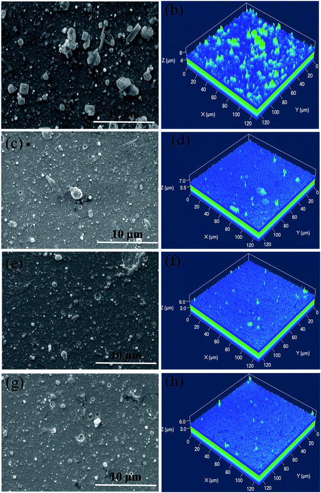 | ||
| Fig. 1 Surface and AFM morphologies of as-prepared CrAlSiN coating systems (a) and (b) CrAlSiN (c) and (d) Cr/CrAlSiN (e) and (f) CrN/CrAlSiN (g) and (h) Cr/CrN/CrAlSiN. | ||
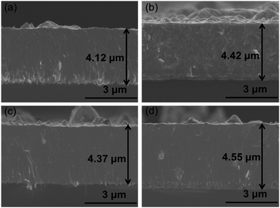 | ||
| Fig. 2 Section morphologies of as-prepared CrAlSiN coating systems (a) CrAlSiN (b) Cr/CrAlSiN (c) CrN/CrAlSiN (d) Cr/CrN/CrAlSiN. | ||
The chemical compositions of CrAlSiN coating with different interlayers were listed in Table 2. It can be seen that the CrAlSiN coating mainly consisted of Cr, Al, Si, N and O elements. The existence of O element indicated some oxide reactions might occur on the coating surface. Moreover, in case of CrAlSiN coating with interlayer design, the Cr content presented a slightly decrease and the Si content displayed an opposite rule compared with the single CrAlSiN coating, especially for Cr/CrN/CrAlSiN coating system. These phenomena suggested that the interlayer design could mildly change the composition of coating.
| Coating | Cr (at%) | Al (at%) | Si (at%) | N (at%) | O (at%) |
|---|---|---|---|---|---|
| CrAlSiN | 26.85 | 15.72 | 2.16 | 53.31 | 1.24 |
| Cr/CrAlSiN | 25.65 | 16.18 | 2.34 | 54.67 | 1.16 |
| CrN/CrAlSiN | 24.93 | 17.62 | 2.25 | 53.68 | 1.52 |
| Cr/CrN/CrAlSiN | 24.04 | 16.21 | 3.72 | 55.01 | 1.02 |
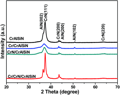
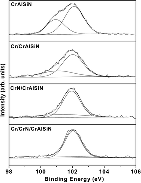
Fig. 3 showed the diffraction pattern for as-prepared CrAlSiN coating systems. A series of peaks at 37.6°, 43.7° and 64.4° corresponded to reflections (111), (200) and (220) of cubic chromium nitride. Meanwhile, three peaks at 36.2°, 44.2° and 51.5° were attributed to the (002), (200) and (102) of aluminum nitride, indicating the coexistence of chromium nitride and aluminum nitride in these as-prepared CrAlSiN coating systems, which was similar to the previous report.29 Moreover, XRD spectra showed no diffraction peaks of crystal containing Si element, hinting the Si element mainly existed in amorphous phase. By XPS analysis, the result of Si 2p spectra were shown in Fig. 4. It can be observed that the Si 2p spectra were fitted by two components, which around at 102.1 and 100.5 eV, corresponding to Si3N4 and SiO2 bonds, respectively.30 The volume ratio of each bond was listed in Table 3. In detail, the ratio of Si3N4 for CrAlSiN, Cr/CrAlSiN, CrN/CrAlSiN and Cr/CrN/CrAlSiN coatings were about 67.27%, 72.45%, 78.64% and 90.91%, respectively.
| Coatings | SiO2 (%) | Si3N4 (%) |
|---|---|---|
| CrAlSiN | 32.73 | 67.27 |
| Cr/CrAlSiN | 27.55 | 72.45 |
| CrN/CrAlSiN | 21.36 | 78.64 |
| Cr/CrN/CrAlSiN | 9.09 | 90.91 |
To further acquire the information of coating's microstructure, Fig. 5 presented the TEM, HRTEM images and SAED pattern of Cr/CrN/CrAlSiN coating system. Clearly, the CrAlSiN layer presented a typical nanocrystalline/amorphous structure, where the amorphous Si3N4 phase was implanted in the crystalline phases of CrN and AlN (Fig. 5b). The grain sizes of CrN and AlN were about 2–10 nm (Fig. 5a). The SAED pattern was constituted of polycrystalline rings superimposed with spots, which indicated the existence of preferred orientation growth of crystals in this coating. Six obvious rings corresponding to the (111), (200), (222) planes of CrN and the (002), (200), (102) planes of AlN were observed, which were consistent with the results of XRD spectra. In addition, the crystal pattern of Si3N4 phase was not found in the SAED pattern. Combined with the results of XRD, TEM and XPS analysis, the CrAlSiN layer mainly contained amorphous Si3N4 and Cr(Al)N solid-solution phases.21
3.2 Mechanical performance of as-prepared CrAlSiN coating systems
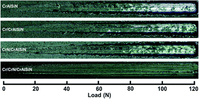
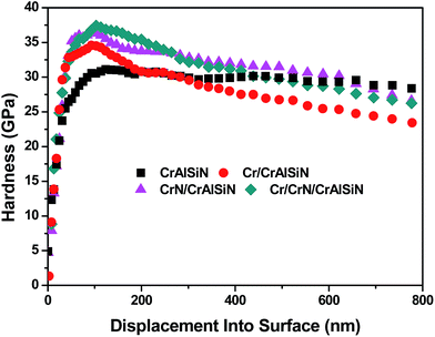
Fig. 6 displayed the scratch morphologies of as-prepared CrAlSiN coating systems during the adhesion test. It can be found that the fracture behaviors of these coating systems were largely related to the interlayer design. Critical load was defined as the load at the first fracture or spallation. In case of single CrAlSiN coating, the critical load was about 38.1 N. After designing the single interlayer, the critical load of Cr/CrAlSiN and CrN/CrAlSiN coating systems were enhanced to 44.8 and 51.6 N, respectively. However, in terms of Cr/CrN/CrAlSiN coating system, the critical load was the highest value of 72.5 N. It is worth mentioning that the bare substrate was observed on the surface of single CrAlSiN, Cr/CrAlSiN and CrN/CrAlSiN coatings. Nevertheless, no distinct peeling sign was found on the surface of Cr/CrN/CrAlSiN coating system, implying the best adhesion force between the Cr/CrN/CrAlSiN coating and substrate. Sun et al.30 pointed out that a good adhesion strength between coating and substrate was very important for the wear-resistant protective coating. If the coating occurred stripping in the process of service, the protection capabilities of coating would be greatly reduced and the cracked debris could also cause severe abrasive wear in the friction system.Fig. 7 revealed the nanohardness curves of as-prepared CrAlSiN coating systems with a maximum indentation depth of 800 nm. With the increase of indentation depth, the nanohardness was increasing first and then decreasing slightly. By measurement, it can be seen that the nanohardness of single CrAlSiN coating was about 31.1 GPa. Nevertheless, the nanohardness of Cr/CrAlSiN, CrN/CrAlSiN and Cr/CrN/CrAlSiN coating systems were about 34.5, 36.9 and 37.8 GPa, respectively, which increased by 10.93%, 18.65% and 21.54% compared with single CrAlSiN coating, respectively. The improvement of hardness could be mainly attributed to the addition of Cr, CrN and Cr/CrN interlayers, which could efficaciously enhance the bearing capacity of coating under normal pressure.31 Indentation plasticity is the capacity to resist plastic deformation, which is usually used to measure the ability of a coating to resist mechanical degradation and failure (toughness). It is defined as the ratio of the plastic displacement divided by the total displacement in the load–displacement curve of a nanoindentation measurement.32
 | (3) |
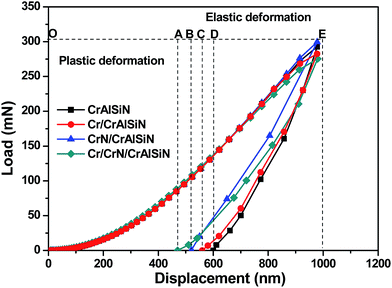 | ||
| Fig. 8 Schematic plot of a nanoindentation load–displacement curve for as-prepared CrAlSiN coating systems. | ||
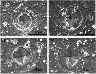 | ||
| Fig. 9 SEM micrographs of indention morphologies after Vickers indentation tests (a) CrAlSiN (b) Cr/CrAlSiN (c) CrN/CrAlSiN (d) Cr/CrN/CrAlSiN. | ||
3.3 Corrosion protection performance of as-prepared CrAlSiN coating systems
Fig. 10 showed the potentiodynamic polarization curves of bare 316L substrate and as-prepared CrAlSiN coating systems after 1 h immersion in seawater. The corrosion potential, corrosion current density and inhibition efficiency were summarized in Table 4. It is clearly that the Tafel curves of as-prepared CrAlSiN coating systems shifted to the positive direction compared with bare substrate, manifesting that these coating systems could effectively inhibit the corrosion tendency of 316L substrate.33–35 And the relationship of corrosion potential was CrAlSiN < Cr/CrAlSiN < CrN/CrAlSiN < Cr/CrN/CrAlSiN. In case of corrosion current density, the 316L substrate presented the highest icorr (7.04 × 10⁻⁶ A cm−2), indicating these coating systems could obviously reduce the icorr values.36–38 It was reported that the formation of nanocomposite structure (Al(Cr)N embedded in amorphous Si3N4 phase) played an important role in the enhancement of corrosion resistance, which could generate an extra resistance for the invasion of corrosive electrolytes.39,40 Surprisingly, the icorr value of Cr/CrN/CrAlSiN coating system was 1–2 orders of magnitude lower than that of other coating systems, indicating that the corrosion rate of 316L substrate was significantly reduced. This could be explained by the barrier ability of interlayer, which could effectively prevent the invasion of corrosion medium. Besides, the inhibition efficiency was well in agreement with the evolution of icorr value, the result of which were 85.37% (CrAlSiN), 93.95% (Cr/CrAlSiN), 96.63% (CrN/CrAlSiN), 98.82% (Cr/CrN/CrAlSiN), suggesting the Cr/CrN/CrAlSiN coating system showed the best anti-corrosion ability during the corrosion test.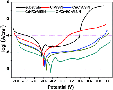 | ||
| Fig. 10 Potentiodynamic polarization curves of 316L substrate and as-prepared CrAlSiN coating systems in seawater solution. | ||
| Sample | Ecorr (mV) | icorr (A cm−2) | IE (%) |
|---|---|---|---|
| 316L | −0.43 | 7.04 × 10⁻⁶ | — |
| CrAlSiN | −0.41 | 1.03 × 10⁻⁶ | 85.37 |
| Cr/CrAlSiN | −0.38 | 4.26 × 10⁻⁷ | 93.95 |
| CrN/CrAlSiN | −0.35 | 2.37 × 10⁻⁷ | 96.63 |
| Cr/CrN/CrAlSiN | −0.26 | 8.28 × 10⁻⁸ | 98.82 |
3.4 Friction and wear behaviors of as-prepared CrAlSiN coating systems
Fig. 11a showed the evolution of friction coefficient of as-prepared CrAlSiN coating systems sliding against WC ball in artificial seawater. It is clearly that all friction curves presented a similar tendency, which sharply increased initially and then decreased slowly, finally reached to steady state. By statistics, the average COFs of all coating systems were displayed in Fig. 11b. For single CrAlSiN coating, the average friction coefficient was about 0.127 ± 0.012. However, the CrAlSiN coating with single interlayer presented lower friction coefficient than the single CrAlSiN coating. The COF values for Cr/CrAlSiN and CrN/CrAlSiN samples were about 0.113 ± 0.014 and 0.112 ± 0.011, respectively. The decrease of COF could be explained by the reduction of surface roughness. The high surface roughness will cause a reduction of the actual contact area between the counterpart and coating, which leads to a high load concentrated in a small area and ultimately enhances the coefficient of friction.41 The lowest COF value of 0.107 ± 0.009 took place on Cr/CrN/CrAlSiN specimen during the friction test. Not only because the surface roughness of Cr/CrN/CrAlSiN sample was lowest, but also because the tribochemical products were formed on the contact interface. During the friction process, silicon nitride can react with water to form silica gel (Si3N4 + 12H2O = 3Si(OH)4 + 4NH3), which can act as a lubricant and then reduce the resistance of interface.42 Combined with the result of Table 3, the content of Si3N4 in Cr/CrN/CrAlSiN coating system was the highest, thus it can be understood that the anti-friction ability of Cr/CrN/CrAlSiN coating system was the strongest.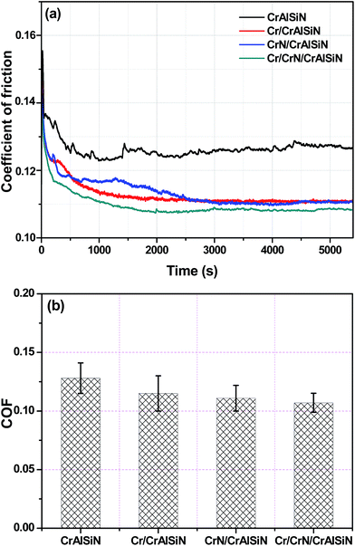 | ||
| Fig. 11 Friction curves (a) and average COF (b) of as-prepared CrAlSiN coating systems in artificial seawater. | ||
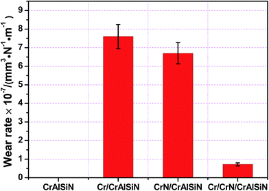
The wear rates for tested coating systems can reflect directly on the wear behavior as shown in Fig. 12. The wear data of single CrAlSiN coating could not be calculated under high load, this was due to the wear track had been worn after the friction test. However, the CrAlSiN coating with interlayer design was not failure. The additive of Cr and CrN interlayers reduced the wear rates of CrAlSiN coating to 7.6 × 10⁻⁷ ± 8.1 × 10⁻⁸ and 6.7 × 10⁻⁷ ± 7.8 × 10⁻⁸ mm3 N−1 m−1, respectively. Meanwhile, the Cr/CrN/CrAlSiN coating system exhibited the lowest wear rate (7.3 × 10⁻⁸ ± 8.4 × 10⁻⁹ mm3 N−1 m−1), which was reduced by one order of magnitude than the CrAlSiN coating with single interlayer. Therefore, as the interlayer, its addition into CrAlSiN coating could take effect on the wear reduction for the composites.
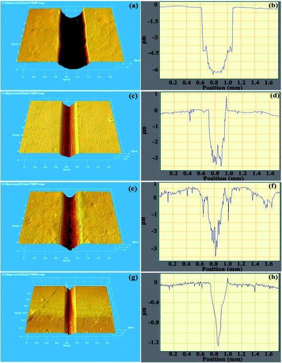
The three-dimensional topographies of wear tracks and dimensional cross-sectional profiles can deeply verify the wear situation, which were shown in Fig. 13. Noticeably, the max depth of single CrAlSiN coating (6.23 μm) was larger than the thickness of this coating (4.12 μm), indicating the single CrAlSiN coating was worn (Fig. 13a and b). With the exception of single CrAlSiN coating, the composite coatings consisted by CrAlSiN coating and different interlayers were not failure. In terms of Cr/CrAlSiN and CrN/CrAlSiN coating systems, some slight furrows and grooves were found on the wear track, this might be due to the fact that the exfoliated particles could effortlessly scratch the surface in the repeated movement. In the meantime, the max depth of wear tracks for Cr/CrAlSiN and CrN/CrAlSiN coating systems decreased to 3.49 and 3.38 μm, respectively, which were 43.98% and 45.74% lower than that of single CrAlSiN coating, respectively, indicating the great improvement of wear resistance (Fig. 13c–f). Furthermore, the max depth of wear track for Cr/CrN/CrAlSiN coating system was the lowest value (1.22 μm) and the track was smooth, suggesting the best anti-wear ability (Fig. 13g and h).
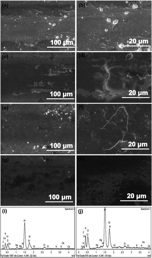
Combined with the morphology and EDS of wear tracks, the wear behavior for as-prepared CrAlSiN coating systems can be illustrated clearly. As shown in Fig. 14a and b, large areas of substrate were exposed in seawater and some salt particles were randomly distributed on the surface of wear track, indicating the single CrAlSiN coating was worn out and the salt was shifted to surface of track. For Cr/CrAlSiN and CrN/CrAlSiN samples, some cracks and desquamates were found in the test region, which ascribed to the synergistic action of both mechanical and corrosion aspects (Fig. 14c–f). Under the mechanical action, the coating was liable to deform or even crack. At this moment, the chloride and hydrogen ions showed a powerful negative function, which could easily enter the crack to induce the corrosion. Then, it would promote the expansion of crack, thereby realizing the wear aggravation. The increased wear triggered more defects and aggravated the corrosion action, finally forming a vicious circle.43 By the EDS analysis, the Cr, Al, Si, N, C, Ca, Mg, K, Na, Cl, W, O and Fe elements were observed on the wear track of Cr/CrAlSiN coating system (Fig. 14i). Among them, Ca, Mg, K, Na and Cl elements came from the artificial seawater, showing these elements were shifted from seawater to wear surface. From previous report, some tribochemical reactions (Mg2+ + 2H2O → Mg(OH)2 + 2H+, HCO3− → CO32− + H+, Ca2+ + CO32− → CaCO3) would occur on the contact interface.11 The formation of Mg(OH)2 and CaCO3 could play a certain role in lubrication. The W element derived from the WC counterpart, indicating W element was shifted from counterpart to wear surface. The presence of O element indicated that the wear track was oxidized. Sun et al.30 confirmed that the oxygen could react with the aluminum/chromium/silicon to form aluminum oxide/chromic oxide/silicon dioxide on the contact interface, which could avoid the direct contact and then enhance the anti-wear property of coating. Interestingly, the wear track was not worn while the Fe was detected in the EDS spectrum, manifesting the thickness of remaining coating was less than the detect depth of the EDS equipment. For Cr/CrN/CrAlSiN specimen, the wear track was flat, no obvious cracks and desquamates were detected, indicating the slightly wear (Fig. 14g and h). In addition, as shown in Fig. 14j, the Fe element was missing, which also verified that the depth of wear track for Cr/CrN/CrAlSiN coating system was lower compared with Cr/CrAlSiN sample in Fig. 14i.
To better summarized the mechanism, the wear models of as-prepared CrAlSiN coating systems under sliding-friction condition in artificial seawater could be seen Fig. 15. Generally speaking, some defects, such as micro-pores and micro-cracks, were unavoidable in all coating systems during the previous deposition process. Compared with CrAlSiN coating with interlayer design, the single CrAlSiN coating exhibited a relatively low toughness and a comparatively high icorr value. Hence, partial micro-cracks and corrosion dimples were easily extended and then formed a small number of corrosion channel (Fig. 15a). At this time, some ions, such as Cl−, H+, OH−, could easily enter into the coating along the corrosive channel and then produced the primary cell, slowly invaded the substrate and damaged the coating. In spite of some protective films might form on surface of coating during the corrosion process. Nevertheless, the protective film was easily destroyed by reciprocating sliding, resulting in the fresh surface directly exposed to corrosive solution. This corrosive medium would gradually erode the fresh surface and then induced a few new defects, ultimately exacerbated the occurrence of erosion. Once more defects and erosion were generated, the deformation would cause the cracks expand and propagate parallel to the surface at a depth, eventually leading to a degree of desquamation.43
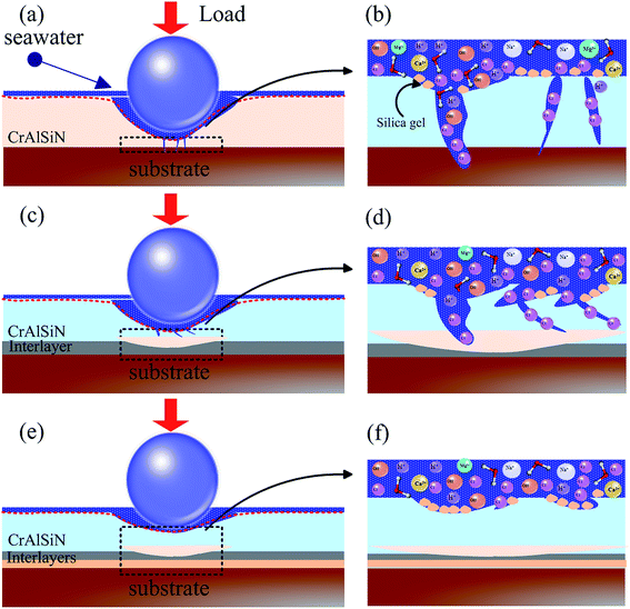 | ||
| Fig. 15 Wear models of as-prepared CrAlSiN coating systems in artificial seawater (a) and (b) CrAlSiN (c) and (d) Cr/CrAlSiN and CrN/CrAlSiN (e) and (f) Cr/CrN/CrAlSiN. | ||
For Cr/CrAlSiN and CrN/CrAlSiN samples, to a certain extent, the toughness and adhesion force were improved due to the addition of single interlayer (Fig. 15c and d). In other words, the abilities to resist the crack propagation and coating peeling were mildly enhanced, which could effectively inhibit the permeation of corrosion medium. Ultimately, the crack propagation was partially suppressed and the wear situation was slightly improved compared to single CrAlSiN coating. However, for Cr/CrN/CrAlSiN specimen, due to high hardness, good adhesion force, outstanding toughness and excellent corrosion resistance, there were not obvious cracks and corrosion defects on the wear track (Fig. 15e). In the microscopic area, some corrosion micro-holes and silicic acid sol particles were observed in Fig. 15f. The silicic acid sol particle could effectively reduce the surface energy of Cr/CrN/CrAlSiN coated substrate and alleviate the adhesive phenomenon. Synchronously, it not only could play a signally lubrication, but also could availably block the infiltration of corrosive medium.44 Thus, it was reasonable that the Cr/CrN/CrAlSiN coating system presented the best anti-wear and anti-corrosion abilities in seawater.
4. Conclusion
By arc ion plating technology, all CrAlSiN coating systems (single CrAlSiN, Cr/CrAlSiN, CrN/CrAlSiN, Cr/CrN/CrAlSiN) were prepared on 316L steel and silicon wafer. The effects of interlayer design on mechanical, corrosion and tribological behaviors were detailedly discussed. The CrAlSiN layer exhibited a typical nanocrystalline/amorphous structure in which nanocrystalline compounds were embedded in the amorphous Si3N4 matrix, and the amorphous Si3N4 around the nanocrystalline CrN and AlN boundaries exhibited a fine grained crystalline structure. Compared with single CrAlSiN coating, the CrAlSiN coating with interlayer design presented a higher hardness and stronger adhesion force, especially for Cr/CrN/CrAlSiN coating system. The relationship of toughness was CrAlSiN < Cr/CrAlSiN < CrN/CrAlSiN < Cr/CrN/CrAlSiN. Due to the best physical shielding effect, the corrosion current density of Cr/CrN/CrAlSiN coating system (8.28 × 10⁻⁸ A cm−2) was 1–2 orders of magnitude lower than that of other coating systems. During the friction and wear test, the Cr/CrN/CrAlSiN coating system presented the lowest friction coefficient (0.107 ± 0.009) and wear rate (7.3 × 10⁻⁸ ± 8.4 × 10⁻⁹ mm3 N−1 m−1) in seawater, this was inseparable from the good mechanical and anti-corrosion properties. Therefore, CrAlSiN coating with proper interlayer could exhibit an ideal comprehensive performance.Conflicts of interest
There are no conflicts to declare.Acknowledgements
The authors gratefully appreciate financial support provided by the National Key R&D Program of China (2016YFE0203600), the National Natural Science Foundation of China (51475449).References
- X. Guan, Y. Wang, J. Wang and Q. Xue, Tribol. Int., 2016, 96, 307–316 CrossRef CAS.
- F. Sun, S. Ren, Z. Li, Z. Liu, X. Li and C. Du, J. Mater. Sci. Eng. A, 2017, 685, 145–153 CrossRef CAS.
- L. Zhou, Z. Liu, W. Wu, X. Li, C. Du and B. Jiang, Int. J. Hydrogen Energy, 2017, 42, 26162–26174 CrossRef CAS.
- Z. Cui, Z. Liu, L. Wang, X. Li, C. Du and X. Wang, J. Mater. Sci. Eng. A, 2016, 677, 259–273 CrossRef CAS.
- W. Hao, Z. Liu, W. Wu, X. Li, C. Du and D. Zhang, J. Mater. Sci. Eng. A, 2018, 710, 318–328 CrossRef CAS.
- L. Zhang, F. Wang, L. Qiang, K. Gao, B. Zhang and J. Zhang, RSC Adv., 2015, 5, 9635–9649 RSC.
- Y. Ye, C. Wang, H. Chen, Y. Wang, J. Li and F. Ma, RSC Adv., 2016, 6, 32922–32931 RSC.
- X. Guan, Y. Wang, G. Zhang, J. Wang and Q. Xue, Surf. Interface Anal., 2017, 49, 323–333 CrossRef CAS.
- I. Bertóti, M. Mohai, P. H. Mayrhofer and C. Mitterer, Surf. Interface Anal., 2002, 34, 740–743 CrossRef.
- C. Kunze, R. H. Brugnara, N. Bagcivan, K. Bobzin and G. Grundmeier, Surf. Interface Anal., 2013, 45, 1884–1892 CrossRef CAS.
- Y. Ye, C. Wang, H. Chen, J. Li, Y. Yao and C. Wang, Tribol. Int., 2015, 90, 362–371 CrossRef CAS.
- Y. Ye, Y. Wang, C. Wang, J. Li and Y. Yao, Tribol. Int., 2015, 91, 131–139 CrossRef CAS.
- Y. Ye, C. Wang, H. Chen, J. Li, S. Zhou and Q. Xue, Surf. Coat. Technol., 2015, 270, 305–313 CrossRef CAS.
- K. Bobzin, N. Bagcivan, P. Immich, S. Bolz, R. Cremer and T. Leyendecker, Thin Solid Films, 2008, 517, 1251–1256 CrossRef CAS.
- W. Y. Ho, C. H. Hsu, C.-W. Chen and D. Y. Wang, Appl. Surf. Sci., 2011, 257, 3770–3775 CrossRef CAS.
- S. K. Kim, V. V. Le, P. V. Vinh and J. W. Lee, Surf. Coat. Technol., 2008, 202, 5400–5404 CrossRef CAS.
- S. H. Shin, M. W. Kim, M. C. Kang, K. H. Kim, D. H. Kwon and J. S. Kim, Surf. Coat. Technol., 2008, 202, 5613–5616 CrossRef CAS.
- S. Tan, X. Zhang, X. Wu, F. Fang and J. Jiang, Appl. Surf. Sci., 2011, 257, 1850–1853 CrossRef CAS.
- H. C. Barshilia, N. Selvakumar, B. Deepthi and K. S. Rajam, Surf. Coat. Technol., 2006, 201, 2193–2201 CrossRef CAS.
- T. Polcar and A. Cavaleiro, Surf. Coat. Technol., 2011, 206, 1244–1251 CrossRef CAS.
- H. W. Chen, Y. C. Chan, J. W. Lee and J. D. Duh, Surf. Coat. Technol., 2010, 205, 1189–1194 CrossRef CAS.
- C. H. Lin and J. D. Duh, Surf. Coat. Technol., 2009, 204, 784–787 CrossRef CAS.
- S. K. Kim, V. V. Le, P. V. Vinh and J. W. Lee, Surf. Coat. Technol., 2008, 202, 5400–5404 CrossRef CAS.
- X. Ding, X. T. Zeng and Y. C. Liu, Thin Solid Films, 2011, 519, 1894–1900 CrossRef CAS.
- W. Ho, C. Hsu, C. Chen and D. Wang, Appl. Surf. Sci., 2011, 257, 3770–3775 CrossRef CAS.
- F. Yang, X. Li, S. Qiu, W. Zheng, H. Zhao and L. Wang, Int. J. Electrochem. Sci., 2017, 12, 5349–5362 CrossRef CAS.
- R. Gåhlin, M. Bromark, P. Hedenqvist, S. Hogmark and G. Håkansson, Surf. Coat. Technol., 1995, 76–77, 174–180 CrossRef.
- F. Sanchette, C. Ducros, T. Schmitt, P. Steyer and A. Billard, Surf. Coat. Technol., 2011, 205, 5444–5453 CrossRef CAS.
- T. Polcar, T. Vitu, J. Sondor and A. Cavaleiro, Plasma Processes Polym., 2009, 6, 935–940 CrossRef.
- S. Q. Sun, Y. W. Ye, Y. X. Wang, M. Q. Liu, X. Liu, J. L. Li and L. P. Wang, Tribol. Int., 2017, 115, 591–599 CrossRef CAS.
- C. Tritremmel, R. Daniel, M. Lechthaler, P. Polcik and C. Mitterer, Thin Solid Films, 2013, 534, 403–409 CrossRef CAS.
- Y. V. Milman, B. Galanov and S. Chugunova, Acta Metall. Mater., 1993, 41, 2523–2532 CrossRef CAS.
- Q. Hou, Z. Liu, C. Li and X. Li, Corros. Sci., 2017, 128, 154–163 CrossRef CAS.
- C. Liu, R. I. Revilla, Z. Liu, D. Zhang, X. Li and H. Terryn, Corros. Sci., 2017, 129, 82–90 CrossRef CAS.
- Z. Liu, X. Li and Y. Cheng, Electrochim. Acta, 2012, 60, 259–263 CrossRef CAS.
- Z. Liu, X. Li, C. Du and Y. Cheng, Corros. Sci., 2009, 51, 2863–2871 CrossRef CAS.
- D. Zhang, H. Qian, L. Wang and X. Li, Corros. Sci., 2016, 103, 230–241 CrossRef CAS.
- Z. Liu, X. Li and Y. Cheng, Electrochim. Acta, 2011, 56, 4167–4175 CrossRef CAS.
- N. Fukumoto, H. Ezura and T. Suzuki, Surf. Coat. Technol., 2009, 204, 902–906 CrossRef CAS.
- L. Zhang, Y. Chen, Y. Feng, S. Chen, Q. Wan and J. Zhu, Int. J. Refract. Met. Hard Mater., 2015, 53, 68–73 CrossRef CAS.
- R. A. Al-Samarai, K. R. A. Haftirman and Y. Al-Douri, Int. J. Appl. Sci. Eng. Res., 2012, 2, 2229–5518 Search PubMed.
- L. Shan, Y. Zhang, Y. Wang, J. Li, X. Jiang and J. Chen, Trans. Nonferrous Met. Soc. China, 2016, 26, 175–184 CrossRef CAS.
- L. Shan, Y. Wang, J. Li, X. Jiang and J. Chen, Surf. Coat. Technol., 2014, 242, 74–82 CrossRef CAS.
- F. Zhou, K. Chen, M. Wang, X. Xu, H. Meng and M. Yu, Wear, 2008, 265, 1029–1037 CrossRef CAS.
| This journal is © The Royal Society of Chemistry 2018 |

