DOI:
10.1039/C7RA12030C
(Paper)
RSC Adv., 2018,
8, 3599-3610
Synthesis and characterization of graphene oxide sheets integrated with gold nanoparticles and their applications to adsorptive removal and catalytic reduction of water contaminants†
Received
1st November 2017
, Accepted 31st December 2017
First published on 17th January 2018
Abstract
Here, we report the facile synthesis of graphene oxide–gold (GO–Au) nanocomposites and their use as adsorbents for the removal of toxic industrial dyes from water and as catalysts for the individual and simultaneous reduction of a dye and a nitro compound in aqueous medium. GO sheets were prepared using a modified Hummers method while Au nanoparticles were integrated on GO sheets by reducing Au(III) ions on the surfaces of GO sheets using sodium citrate as a reducing agent. The prepared composite was characterized with field emission scanning electron microscopy (FESEM), transmission electron microscopy (TEM), elemental dispersive X-ray analysis (EDX), X-ray diffraction (XRD), Fourier transform infra-red (FT-IR) spectroscopy and thermal gravimetric analysis (TGA). The GO–Au nanocomposite demonstrated efficient adsorption capacities and recyclability for malachite green (MG) and ethyl violet (EV) dyes. The effects of various experimental parameters including temperature, pH, contact time, and adsorbent dose were studied. From the simulation of experimental data with different adsorption isotherms and kinetic models it was found that the adsorption of both the dyes followed the Freundlich adsorption model and a pseudo-second order kinetic model, respectively. Moreover, the adsorbent showed better recyclability for both dyes without any compromise on the removal efficiency. Similarly, the catalytic performance for the reduction of 2-nitroaniline (2-NA) has been investigated in detail by using the prepared nanocomposite as a catalyst. Most importantly, we reported the simultaneous adsorption of cationic and anionic dyes from water using the prepared nanocomposite as well as the simultaneous catalytic reduction of a mixture of EV and 2-NA. So, considering the facile synthesis process and the efficient removal of a variety of dyes and the catalytic performance this work opens up a tremendous opportunity to bring GO based nanocomposites from experimental research to practically applied materials for wastewater treatment.
Introduction
Since the industrial revolution the use of dyestuffs and aromatic pollutants has increased worldwide. Due to their release into waste water from different industries like paper, plastic, cosmetics, leather and textile, water is becoming unfit for life on earth.1 This water pollution has become a worldwide problem as water is an essential element to sustain living organisms. The occurrence of dyes and aromatic pollutants in water, even at a very low level, is highly noticeable and unwanted. The high visibility of the dyes in aqueous medium, and the recalcitrance and resistance of various dyes to light, heat and oxidizing agents are significant problems associated with the dyes.2 Mostly all the dyes cause serious health problems like allergies, skin problems and cancer in humans. A large number of physical, chemical and biological technologies like reverse osmosis, electrochemical treatment, membrane filtration, adsorption, catalysis, ion exchange, coagulation and spectrophotometric methods have been developed to remove these pollutants from water.3–6 However, some of these methods have the limitations of being costly, less sensitive and complex. Adsorption is considered to be one of the best methods due to its simplicity, easy operation and wide suitability for diverse dyes.7–9 Adsorption also does not result in secondary pollution by producing hazardous substances during the process. During adsorption, the pollutants are removed from water without any change in chemical composition. Later on, these pollutants can be recovered from the adsorbent by desorption in a suitable medium and can be made reusable after purification. Therefore, researchers have always been in effort to find new adsorbents with better efficiency. An efficient adsorbent is expected to show high adsorption capacity, rapid adsorption rate and high selectivity.3,4 Presently, many different porous materials like activated carbon, zeolites, clay, metal organic frameworks etc. have been used as an adsorbent and as catalyst for waste water treatment.10,11 Of these, carbon based materials have become more popular due to their high adsorption capacity which is achieved as result of development of van der Waals force between sp2-hybridized carbon domains and aromatic structure of dyes, and electrostatic interaction between dyes and carbonaceous material.12 Except for the removal of dyes, such carbonaceous materials have also potential to adsorb heavy metal ions such as Cd(II).13 This ability of carbon based materials to adsorb a wide variety of pollutants has increased their demand as adsorbent in water purification. GO, a two dimensional carbon nanomaterial with a single layer of sp2 hybridized carbon atoms, has an abundance of hydrophilic groups on its surface such as epoxides, hydroxyl and carboxylic groups. The large surface area, excellent water dispersibility, and substantial hydrophilic groups make GO a material of great interest in water purification based techniques.14,15 Many research groups have reported the use of GO based materials as an adsorbent for dye removal.16–20 The acidic surface and oxygen containing groups on GO play an important role in enhancing the adsorption capacity of GO for cationic dye.14 However, it is hard to separate highly water dispersible GO adsorbent from aqueous solution after the completion of adsorption. Also, in non-aqueous medium GO undergoes agglomeration and precipitation upon reduction due to the strong π–π stacking and van der Waals interaction between carbon layers. Due to this deformation in GO sheet, its surface area is decreased which limits the application potential of GO sheets especially for their exploitation in contamination adsorption where high surface area is required.21 To overcome this problem, hybridization of GO with other inorganic and organic materials have been studied. Graphene based composites are the novel hybrid materials where inorganic particles are synthesized onto the graphene sheets to prevent the nanoparticles agglomeration and restacking of graphene layers so that these composite materials can show enhanced adsorptive and additional catalytic properties. In this context, Cheng et al.22 designed GO based magnetic composite gels by combining GO with poly(vinyl alcohol) and platinum (Pt) nanoparticles and studied their adsorptive and catalytic applications. The authors observed that these composite gels were not only having remarkable high adsorption capacity but also exhibit a simple and convenient separation capability by the application of external magnetic field. Also, Pt nanoparticles containing composite gels were found to possess excellent catalytic properties. Similarly, Hsu et al.23 prepared nanocomposite consisting of reduced GO and silver (Ag) nanoparticles. The presence of Ag nanoparticles not only added the catalytic characteristics to the prepared nanocomposite but also facilitated the removal of catalyst for reusing by controlling the affinity of nanocomposite towards water. Li et al.24 synthesized magnetic CoFe2O4-functionalized graphene nanosheets for the removal of methyl orange (MO) from aqueous solution. Similarly, Liu et al.25 fabricated the carbon coated Fe2O3 NPs on GO sheets and studied the removal of toxic dyes and the recyclability of adsorbent. In this work, we have prepared GO–Au nanocomposite for adsorptive removal of cationic and anionic dyes from water and as catalyst for the individual and simultaneous reduction of a dye and a nitro compound in aqueous medium. To the best of our knowledge, detailed adsorption of MG and EV as well as catalytic reduction of 2-NA has not been studied using Au nanoparticles coated graphene oxide nanosheets. The details of influential factors such as pH, temperature, dosage, and contact time were studied for both the dyes. Adsorption data was also simulated with adsorption kinetics and isotherms. The reusability of the adsorbent was also investigated. Catalytic performance for the reduction of 2-NA was also studied in detail. Most importantly, the simultaneous adsorption of cationic and anionic dyes as well as degradation of mixture of EV dye and 2-NA was reported for the first time using graphene based nanostructures. Since the industrial wastes may contain variety of pollutants, their simultaneous removal from industrial water is highly advantageous. Although Au is an expensive material to be used as adsorbent, however, owing to its additional benefits such as prevention of aggregation of GO sheets upon reduction, catalytic and anti-microbial properties, and easy removal of GO sheets from adsorption/catalysis medium, it can be sacrificially used to perform these multi tasks.
Experimental
Materials and methods used for the preparation of GO, GO–Au nanocomposite, the procedure for conducting adsorption and catalytic experiments are given in ESI.†
Results and discussion
Morphology and structure of GO–Au nanocomposites
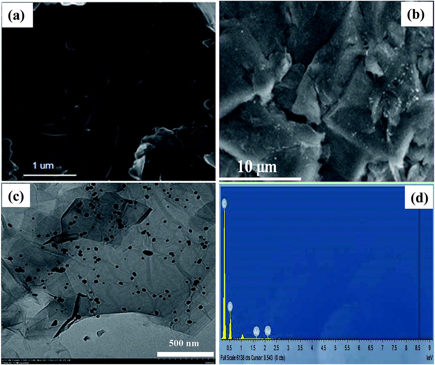
Morphology and structure of GO sheets and GO–Au nanocomposite was investigated with FE-SEM, TEM, XRD and FT-IR techniques. FE-SEM images in Fig. 1(a) and (b) illustrate the morphology of GO and GO–Au nanocomposite, respectively. GO sheets were prepared with smooth and planar surfaces containing some wrinkles. In Fig. 1(b) the white spots on surface of GO represent the presence of Au nanoparticles. Typical wrinkle like pattern of GO can also be visualized in the FE-SEM image of composite which shows that GO sheets have retained their structure during the integration of Au nanoparticles on their surfaces.26 In order to have more insight into the surface morphology and dispersity of Au nanoparticles grown on the surface of GO sheets TEM image of Au nanoparticles was recorded. Fig. 1(c) represents TEM image Au nanoparticles integrated on the surface of GO sheets. The TEM image shows that size of most of the Au nanoparticles was around 50 nm and these nanoparticles were almost uniformly distributed throughout the surface of GO sheets.26 Formation of Au nanoparticles of almost homogenous shape and narrow size distribution on the surface of GO sheets without any aggregation shows that GO sheets can act as a valuable supports for the growth and dispersity of nanoparticles. The EDX was performed to analyse the surface heterogeneity of GO–Au nanocomposite as shown in Fig. 1(d). EDX spectrum confirms the presence of Au nanoparticles and the intense signals of C and O confirm the presence of GO as well in the GO–Au composite. Absence of any extra signal evidenced the high purity of sample which was achieved by washing the sample many times repeated cycles of water and methanol to remove any unwanted ions. Due to good affinity of H+ and Cl− ions towards water, these ions were removed from the prepared composite along with water during washing. A minute amount of these ions may remain present in the prepared sample and therefore, their signals in EDX can be suppressed.
 |
| | Fig. 1 Scanning electron microscope image of (a) bare graphene oxide (b) graphene oxide–gold nanocomposite, (c) transmission electron microscopic image of graphene oxide–gold nanocomposites (d) elemental dispersive X-ray spectrum of graphene oxide–gold nanocomposite. | |
The crystal structure of GO–Au nanocomposite was characterized by XRD and the stacked XRD pattern of GO and GO–Au nanocomposite are shown in Fig. 2(a). For pure GO an intense and sharp peak is observed at 2θ = 10.2. Different functional moieties like carboxyl, hydroxyl and epoxy groups could be responsible for large interlayer distance in GO.27 In XRD pattern of GO–Au absence of any extra signal for graphene oxide indicate the purity of the sample. Secondly, it also indicates that Au nanoparticles effectively prevented the restacking of GO layers.27 XRD peaks in GO–Au nanocomposite matches well to the face centred cubic crystalline Au (ICDD code 00-002-1095).26 Moreover, the presence of all the characteristic Au signals in the nanocomposite confirms that it retained its phase and crystallinity even in the composite form. So, graphene sheets act only as a substrate for the formation of nanoparticles. TGA was used to identify the thermal behaviour of GO and Go–Au nanocomposites. Also, it indicates the presence of Au nanoparticles on GO sheets and also the effect of Au nanoparticles on the thermal stability of GO. Thermograms of GO and GO–Au are shown in Fig. 2(b). It is clearly evident from thermograms that thermal stability of GO–Au composite was higher as compared to GO. A 15% of the weight loss of GO was occurred up to 100 °C which can be mainly due to the evaporation of water contaminated in the sample. The major weight loss was observed around 200 °C and it can be due to the decomposition of oxygen containing groups in the GO sheet such as hydroxyl, epoxy, carboxyl and carbonyl groups as well as the breakdown of carbon skeleton.28
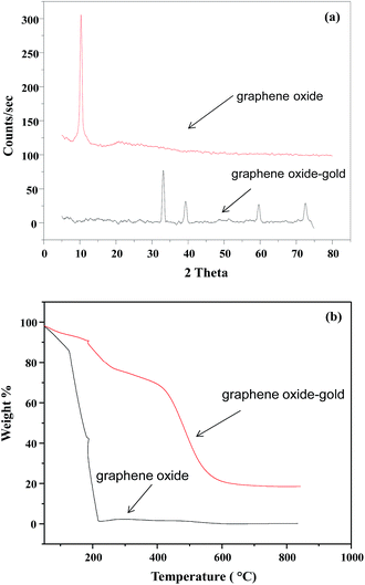 |
| | Fig. 2 (a) X-ray diffraction pattern of graphene oxide and graphene oxide–gold nanocomposite (b) thermal gravimetric analysis curves of graphene oxide and graphene oxide–gold nanocomposite. | |
However, in case of composite as can be seen in the thermal stability was much increased. The overall weight loss was observed in three successive steps. Almost 10% weight loss occurred up to 210 °C and this can be attributed to the removal of water molecules. Almost 20% weight loss occurred as the temperature was raised from 210 °C and up to 400 °C. This is due to the decomposition of oxygen containing moieties in the structure. Another 38% weight loss occurred when the nanocomposite was heated from 400 °C to 600 °C. This was most likely due to the decomposition of carbon skeleton of GO.28 So, the nanocomposite has the greater thermal stability than bare GO sheets. Presence of Au nanoparticles controls the thermal motion of graphene sheets in the composite and increase thermal stability. ESI Fig. S1† represents the FT-IR spectra of GO and GO–Au nanocomposites prepared. In the FT-IR spectra of GO the absorption band at 3152 cm−1 corresponds to hydrogen bonding between GO and water contaminated on GO sheets. C![[double bond, length as m-dash]](https://www.rsc.org/images/entities/char_e001.gif) O stretching vibrations was appeared at 1714 cm−1, a band at 1614 cm−1 was appeared relating to sp2 framework of GO. For C–OH stretching the absorption band was observed at 1996 cm−1 and the band at 1033 cm−1 was due to C–O stretching of epoxy.29 In case of GO–Au composite, the diminution of FT-IR bands at 3152 cm−1 and 1033 cm−1 indicate the formation of GO–Au nanocomposite through carboxyl moieties. The bands at 1557 cm−1 and 1365 cm−1 corresponds to the symmetric and asymmetric COO− vibrations complexed with Au nanoparticles. So, the FT-IR analysis supported the formation of GO–Au nanocomposite. Further, the FT-IR spectrum of composite implies that presence of nanoparticles have not any influenced the structure of GO.
O stretching vibrations was appeared at 1714 cm−1, a band at 1614 cm−1 was appeared relating to sp2 framework of GO. For C–OH stretching the absorption band was observed at 1996 cm−1 and the band at 1033 cm−1 was due to C–O stretching of epoxy.29 In case of GO–Au composite, the diminution of FT-IR bands at 3152 cm−1 and 1033 cm−1 indicate the formation of GO–Au nanocomposite through carboxyl moieties. The bands at 1557 cm−1 and 1365 cm−1 corresponds to the symmetric and asymmetric COO− vibrations complexed with Au nanoparticles. So, the FT-IR analysis supported the formation of GO–Au nanocomposite. Further, the FT-IR spectrum of composite implies that presence of nanoparticles have not any influenced the structure of GO.
Adsorption study
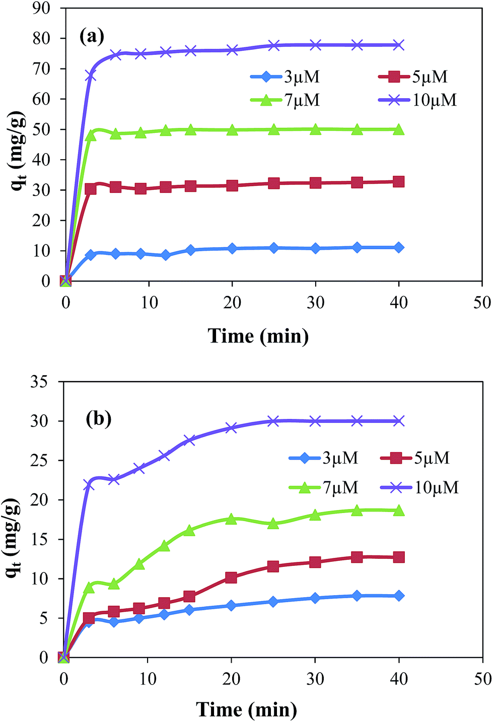
The adsorption study was carried out for the removal of MG and EV form aqueous medium using GO and GO–Au as adsorbent. The amounts of MG and EV adsorbed in GO–Au composite were calculated by measuring the absorbance at the absorption maxima of λ = 617 nm and 595 nm for MG and EV, respectively. It is well known fact that the rate of adsorption of dyes on GO–Au nanocomposite and the amount of dye adsorbed on adsorbent is highly influenced by the initial concentration of dyes, amount of adsorbent used, the temperature and the pH of adsorption medium. Therefore, effects of these parameters were systematically studied. First of all adsorption capacities of GO and GO–Au nanocomposite were studied and compared for the adsorptive removal of both the MG and EV. For this purpose, 0.005 g of each of GO and GO–Au nanocomposite was added as adsorbent in 50 ml of 10 μM aqueous solution of each dye in separate containers. Amounts of dyes adsorbed on per gram of each adsorbent are shown in ESI Fig. S2† in terms of plots of adsorbed amounts as a function of time. As the figure demonstrates, the adsorption capacity as well as adsorption rate of GO–Au nanocomposite was higher as compared to that of GO. Such an increase in the adsorption capacity can be achieved to relatively higher adsorption capacity of Au nanoparticles which are integrated on GO sheets. The higher surface energy of gold nanoparticles causes in increase in their adsorption capacity. Although this increase was not very significant, however integration of gold nanoparticles on GO provides some additional advantages such as prevention of aggregation of GO sheets upon reduction, easy separation from the adsorption medium, increasing shelf life, addition of antimicrobial and catalytic properties of GO based composite. The initial concentration of dyes is an important driving force to overcome the mass transfer resistance of molecules of dye between adsorbent and adsorbate. The experimental adsorption data with different initial concentrations i.e. 3 μM, 5 μM, 7 μM and 10 μM of MG and EV is shown in Fig. 3(a) and (b), respectively.
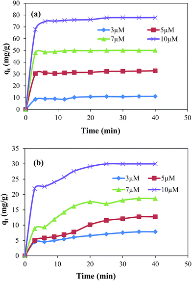 |
| | Fig. 3 Effect of initial concentration of dyes on the adsorbed amount of (a) malachite green and (b) ethyl violet on graphene oxide–gold nanocomposite. Reaction conditions; adsorbent = 0.005 g, volume of dyes solution = 50 ml, 100 rpm, 25 °C. | |
The results show that with the increase in initial concentration of dyes the adsorption rates as well as the adsorbed amounts of dyes were increased. This increase can be explained in terms of concentration gradient developed between concentration of dyes in their aqueous solutions and concentration of dyes on the adsorbent.30,31 This concentration gradient increases with the increase in initial concentrations of dyes due to which greater numbers of molecules of dyes diffuse from the surrounding to the surface of adsorbent. The increase in total adsorbed amount with the increase in initial concentration of dyes can be attributed to the availability of greater number of adsorbate molecules in the adsorption medium. The experimental data also evidenced that the removal rate was rapid during the initial period of contact time and then become slow afterwards. This rapid adsorption rate at initial stage adsorption is due to the presence of large number of active sites on GO–Au composite and higher concentration gradient between adsorbent and adsorbate.30 The equilibrium adsorbed amount increased from 11.11 mg g−1 to 77.82 mg g−1 in case of MG and from 7.83 mg g−1 to 30 mg g−1 in case of EV when the initial concentration was increased from 3 μM to 10 μM. For the adsorption of MG, the equilibrium was established in 3 to 5 minutes. However, in case of EV the equilibrium condition was achieved within first 20 to 30 minutes depending upon the initial concentration of adsorbate in the adsorption medium. The lower adsorption capacity of GO–Au for EV may be achieved due to its relatively bulky structure of EV.
The effect of different amounts of nanocomposite on the rate of adsorption was also studied by using three different amounts of adsorbent i.e. 0.003 g, 0.005 g and 0.007 g keeping all other parameters constant e.g. concentrations of MG and EV (5 μM), volume of solutions (50 ml) and temperature (25 °C). Experimental results revealed that at fixed dyes concentrations the equilibrium adsorbed amount increases from 25 mg g−1 to 58 mg g−1 in case of MG and from 13 mg g−1 to 31.78 mg g−1 in case of EV dye with the increase in nanocomposite dosage as shown in ESI Fig. S3(a) and (b)† respectively. These results are obvious due to the availability of greater number of active sites in the adsorption medium and hence greater interaction with the dye molecules.31,32 Another important parameter which affects the adsorption process is temperature. Temperature affects the adsorption process by two ways. Firstly, an increase the temperature increases the diffusion rate of adsorbate molecules across the external boundary as well as in the internal pores of the adsorbent. Such an increase in diffusion rate is observed due to increase in average kinetic energy of adsorbate molecules. So the increase in temperature decreases the viscosity of the solution. Secondly, it affects the equilibrium adsorption capacity of the adsorbent depending upon the nature of adsorbate.33–36 Also, the study of temperature dependence of adsorption process provides information about the enthalpy and entropy changes during the adsorption process. In this work, the effect of temperature on the adsorption process was studied in the temperature window of 25 to 45 °C for 50 ml, 10 μM solution of each dye containing 0.005 g adsorbent. The % removal of MG and EV is shown in ESI Fig. S4(a).† The results indicated that adsorption capacity was increased with the increase in temperature in case of both dyes. Actually, increase in temperature causes the dye molecules to acquire sufficient energy to interact with the active sites on the adsorbent surface. This is also in agreement with the endothermic nature of the adsorption process33 which was confirmed from experimentally calculated thermodynamic parameters. In order to get insight into the energetics associated with the adsorption process various thermodynamic parameters were calculated from the following equations for both dyes.
| | ΔG = −RT![[thin space (1/6-em)]](https://www.rsc.org/images/entities/char_2009.gif) lnKd lnKd | (2) |
| | | lnKd = ΔS/R − ΔH/RT | (3) |
In above equations, Kd is the distribution coefficient, T is the temperature in kelvin, ΔH is enthalpy change, ΔG is Gibbs free energy change and ΔS is entropy change. The calculated thermodynamic parameters are shown in ESI Table S1.† ΔH° and ΔS values were evaluated from slope and intercept of plot of lnKd verses 1/T which are shown in ESI Fig. S4(b).† The negative Gibbs free energy values at different temperatures evidenced the feasibility and spontaneity of adsorption of dyes on GO–Au nanocomposite.37 The positive ΔH values of both dyes confirm the endothermic nature of adsorption process. Also, the positive entropy change values of both dyes suggests an increase in randomness at dye/adsorbent interface during the process of adsorption thus indicating a good affinity of both dyes toward GO–Au nanocomposite.34–36 The pH is also an important environmental factor that affects the adsorption process. Different functional groups present on the surface of adsorbent and adsorbate can be protonated and deprotonated to produce different charged species in the medium at various pH values of the adsorption medium. As a result, electrostatic attractive or repulsive forces operate between charges present on the surface of adsorbent and adsorbate.38 The influence of pH on adsorptive behaviour of both dyes is shown in ESI Fig. S4(c).† The pH of aqueous solutions of dyes was adjusted from 2 to 9 by using 0.1 M NaOH and 0.1 M HCl aqueous solutions. As it is clear from ESI Fig. S3(c)† the maximum adsorption of both dyes from aqueous solution was occurred at pH = 2 and pH = 9 and the minimum was observed at around pH = 7. Similar results were found by W. Tsai et al.39 for the adsorption of EV on regenerated spent bleaching earth (RSBE). Also, Sharma et al.40 reported the similar pH dependent results of cationic dyes removal using GO nanosheets as adsorbent. The equilibrium adsorption capacity increased from 30 mg g−1 to 39.59 mg g−1 for EV and from 69.36 mg g−1 to 71.64 mg g−1 for MG as the pH was increased from 2 to 9. It is known that in case of cationic dyes, adsorption capacity increases with the increase in pH value due to increase in π–π stacking between negatively charged GO sheets and cationic dyes along with the electrostatic attractions that develop between the ions and as a result percent removal of dyes is enhanced.
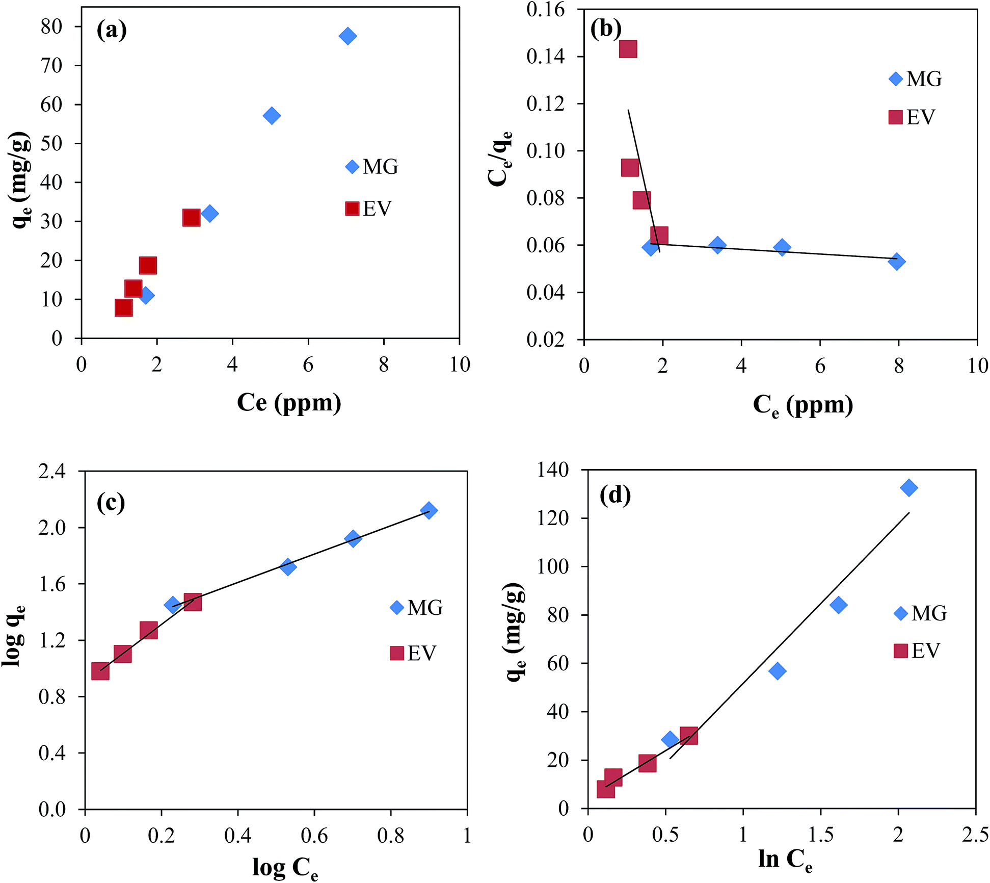
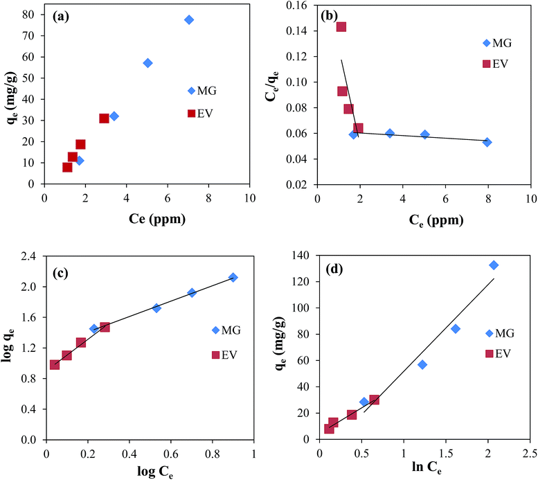
Adsorption isotherms
The experimental results were analysed by using three famous isotherms; Langmuir, Freundlich and Temkin isotherms. The parameters calculated from these isotherms are presented in the Table 1. For the adsorption of both dyes the plot of qe verses Ce is shown in Fig. 4(a).
Table 1 Values of constants of different adsorption isotherms applied on adsorption of malachite green and ethyl violet on graphene oxide–gold nanocomposite. [KL = Langmuir constant, qm = maximum adsorbed amount of adsorbate on per gram of adsorbent at equilibrium, R2 = coefficient of determination, RL = separator factor in Langmuir isotherm, KF = Freundlich adsorption constant, n = equilibrium constants of adsorption intensity, KT = equilibrium binding constant, B = Temkin constant. Reaction conditions; aqueous solution 7 μM EV or 7 μM MG = 50 ml, GO–Au nanocomposite adsorbent = 5 mg, 100 rpm, 30 °C]
| Isotherm |
Constants |
Dye |
| Malachite green |
Ethyl violet |
| Langmuir |
K
L (L g−1) |
0.016 |
0.371 |
|
q
m (mg g−1) |
1000 |
13.33 |
|
R
2
|
0.7201 |
0.6410 |
|
R
L
|
1 |
1 |
| Freundlich |
K
F (L g−1) |
16.136 |
8.00 |
|
n
|
0.993 |
0.500 |
|
R
2
|
0.9972 |
0.9936 |
| Temkin |
K
T (L g−1) |
0.805 |
1.125 |
|
B
|
65.99 |
38.637 |
|
R
2
|
0.9448 |
0.9804 |
 |
| | Fig. 4 Plots of (a) qe verses Ce, (b) Langmuir isotherm, (c) Freundlich isotherm, and (d) Temkin isotherm for the adsorption of MG and EV dyes on GO–Au nanocomposite. Reaction conditions; adsorbent = 0.005 g, concentration of dyes solution = 3, 5, 7, and 10 μM volume of dyes solution = 50 ml, 100 rpm, 25 °C. | |
For the Langmuir adsorption isotherm it is assumed that adsorbent surface is homogenous and all the adsorbent sites are equivalent.41 So a monolayer of adsorbate is formed on the surface of adsorbate. The well-known Langmuir equation used is given below:
| | | Ce/qe = Ce/qm + 1/qmKL | (4) |
where,
Ce is the equilibrium concentration of dye in ppm,
qe is the amount of dye adsorbed per gram of adsorbent (mg g
−1),
qm is the maximum amount of dye adsorbed per gram of nanocomposite (mg g
−1), and
KL is the Langmuir adsorption constant. A plot of
Ce/
qe verses
qe for both the dyes is shown in
Fig. 4(b). The values of coefficient of determination (
R2) were 0.7201 and 0.6405 for MG and EV, respectively. Further, the value of
RL; a dimensionless separation factor, was calculated from the following
eqn (5).
where,
Co is the initial concentration of dye. The value of
RL was found to be 1 for both the dyes and hence indicated that Langmuir adsorption was not favourable. These values of constants of Langmuir adsorption isotherm suggested that adsorption of both the dyes was not followed by Langmuir pattern. In order to take in to account the surface heterogeneity, surface roughness and availability of different types of adsorption sites, Freundlich isotherms was also applied to the experimental data of MG and EV dyes.
42 The Freundlich equation can be expressed as:
| | | logqe = logKF + 1/nlogCe | (6) |
where,
qe is the amount of dye adsorbed per gram of adsorbent at equilibrium state (mg g
−1).
Ce is the equilibrium concentrations of dye in the adsorption medium.
KF and
n are equilibrium constants that represent the adsorption capacity and adsorption intensity, respectively. The plots of log
qe as a function of log
Ce for both the dyes are shown in
Fig. 4(c). The
R2 values of 0.9972 for MG and 0.9936 for EV were evidencing that Freundlich isotherm was favourable for both dyes. The constant 1/
n is a measure of intensity of adsorption. Generally, the value of
n less than unity indicates that Freundlich adsorption was favourable. The values of these constants are shown in
Table 1. The table shows that adsorption of both the dyes on nanocomposite is a physio sorption process. No electron transfer between dyes and adsorbent is taking place during the adsorption process. Also, it indicates that all the adsorption sites are not equally probable so multilayer adsorption can take place on the surface of adsorbent. Both the Langmuir and Freundlich isotherms do not take into account the possible interactions between adsorbent and adsorbate molecules. Temkin and Pyzhev considered some indirect adsorbent/adsorbate interactions in terms of free energy change during the adsorption process and introduced Temkin adsorption isotherm.
43 The Temkin adsorption isotherm is based on the fact that free energy of sorption of molecules in the layer decreases linearly with the surface coverage. The mathematical equation for Temkin isotherm is shown below:
here,
qe is the amount of adsorbate adsorbed per gram of adsorbent at equilibrium state (mg g
−1),
KT is the equilibrium binding constant. The parameter
B is Temkin constant that related to the binding energy. It can be calculated from the following expression:
where,
R is general gas constant,
T is the Kelvin temperature and
bT is the Temkin constant. Temkin plots for both the dyes are shown in the
Fig. 4(d) and the values of constants calculated from these plots are given in the
Table 1. As it can be seen in the
Table 1 both dyes follow Freundlich isotherm better than Langmuir and this is also in quite good agreement with the previously reported results.
42,44
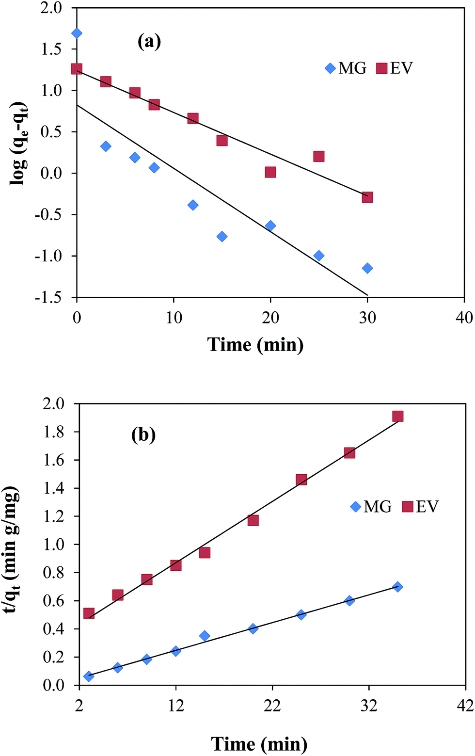
Adsorption kinetics
Adsorption kinetics was also studied in order to get information about the order and rate constants of the reaction. The pseudo first-order and pseudo second-order adsorption kinetic models were applied to study the adsorption of dyes on nanocomposite.
Pseudo first order kinetics
Pseudo first order model is based on the assumption that rate of adsorption is related with the number of unoccupied active sites on adsorbent. The experimental data in the present study was treated with the pseudo first order kinetic model by applying the following mathematical equation;| | | log(qe − qt) = logqe − k1t/2.303 | (9) |
where, qe and qt are the adsorbed amounts (mg g−1) at equilibrium state and at time t (min), k1 (min−1) is the pseudo first order rate constant. According to eqn (9), log(qe − qt) was plotted verses time t as shown in Fig. 5(a). k1 and qe values were calculated from the slope and intercept and are given in ESI Table T2.†
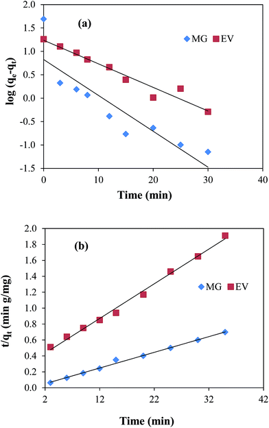 |
| | Fig. 5 Plots of (a) pseudo first-order kinetic medal, (b) pseudo second-order kinetic model for malachite green (MG) and ethyl violet (EV) adsorption. Reaction conditions; 7 μM solution of each dye = 50 ml, 100 rpm, 30 °C. | |
Pseudo second order kinetics
Pseudo second order kinetics depends on both the amount of dye molecules adsorbed on the surface of adsorbent at any time during the course of adsorption process and that adsorbed at equilibrium state. It is represented by the following equation:| | | t/qt = 1/k2qe2 + t/qe | (10) |
where, k2 represents the pseudo second order rate constant (g mg−1 min−1). Graphs of pseudo second order adsorption kinetics were obtained by plotting t/qt as a function of time according to eqn (10) and are shown in Fig. 5(b). All the parameters calculated from the slope and intercept values of straight line graph are given in the ESI Table T2.† From this table it can be seen that the values of R2 for the straight line graphs of both dyes for pseudo second order reaction were found to be very close to 1 as compared to those in pseudo first order reaction. Also, the values of qe calculated from pseudo second order equation are 50.76 mg g−1 and 20.12 mg g−1 for MG and EV, respectively. These values are very close to the experimentally observed values of 50.17 mg g−1 and 18.88 mg g−1 for both dyes.
The linear trend of pseudo second order plots and good resemblance of the qe values calculated from pseudo second order kinetics with those of experimentally observed suggested that the interaction between dyes and the nanocomposite was obeyed by pseudo second order kinetics. This is also in good agreement with the results obtained by earlier researchers for the adsorption of dyes on GO sheets.45,46
Reusability of adsorbent
For the practical application, adsorbent's reusability is an important parameter to cost effective view point. Desorption of both the MG and EV dyes adsorbed on GO–Au nanocomposite was studied in 0.1 M HCl and ethanol. It was observed that 80.5% of MG was desorbed on in 0.1 M HCl and 10% in ethanol. Similarly, almost 8% of EV was desorbed on in 0.1 M HCl and 85% in ethanol. So these results showed that 0.1 M HCl was better desorption medium for MG while ethanol was suitable for EV. Once the adsorbed dyes were desorbed, the adsorbent was washed with DDW and used again for the adsorption of dyes and the process was repeated for four consecutive cycles. The results of reusability of the GO–Au adsorbent for the adsorption of MG and EV are shown in the ESI Fig. S5(a) and (b),† respectively. The reusability results demonstrated that only 10% loss in adsorption capacity was occurred for four consecutive cycles upon using GO–Au nanocomposite for the removal of both MB and EV from water. The gradual but small decrease in adsorption capacity for first four cycles suggests that this adsorbent can be repeatedly used for further few cycles with some more decrease in adsorption capacity. The easy separation of the adsorbent from the adsorption medium, good desorption characteristics and reusability suggests that GO–Au can be applied as effective and economical adsorbent.47
Simultaneous adsorption of cationic and anionic dyes from a dye mixture
An effective adsorbent should have the potential to separate different types of pollutants from contaminated water. To evaluate the potential of GO–Au nanocomposite to adsorb different types of pollutants, the GO–Au nanocomposite was used for simultaneous adsorption of cationic and anionic dyes from water. The GO–Au was added as adsorbent in water containing MG and EV as cationic dyes and methyl orange (MO) as anionic dye. The aqueous solutions of MO, MG and EV were orange, light blue and dark blue coloured as shown by digital camera images (1), (2) and (3), respectively in ESI Fig. S6(a).† The aqueous solution of mixture of these three dyes was green coloured which was turned to pale yellow after adsorption as shown by digital camera images (4) and (5), respectively in ESI Fig. S6(a).† The removal of all the three dyes from water was monitored by UV-vis spectrophotometer. The UV-vis spectra of aqueous solution of mixture of three dyes showed two absorption peaks; one at 600 nm which was related to the mixture of cationic MG and EV dye while the second absorption peak was appeared at 463 nm corresponding to MO. After 15 minutes of adsorption process both the peaks were disappeared representing the removal of dyes from water. The UV-vis absorption spectra of aqueous solution of mixture of MO, MG and EV before and after adsorption are shown in ESI Fig. S6(b).† This simultaneous adsorption is possible due to the neutral surface and high surface reactivity of the GO–Au nanocomposite.48
Interaction of dyes with GO–Au adsorbent
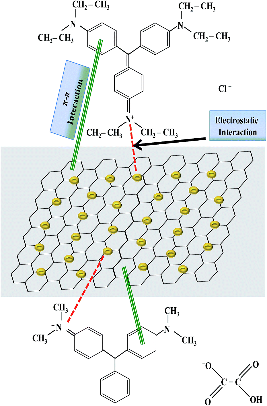
The interaction between the dyes and nanocomposite was confirmed by FT-IR spectroscopy. The FT-IR spectra of MG and EV dyes before and after adsorption on to the GO–Au nanocomposite are shown in ESI Fig. S7.† For EV dye molecules all the corresponding peaks –CH (3079 cm−1), –CH3 (2969 cm−1 and 2866 cm−1) were observed for EV dye. Similarly, the peak at 1517.31 cm−1 was due to the bending of N–H bonds of amide II in the EV. The peak at 1180.91 cm−1 was due to the C–H stretching in the aromatic ring. The peak at 1570 cm−1 was because of CC stretching in the aromatic nuclei of EV dye. Similarly, for free MG dye molecules the peaks at 2916 cm−1 was due to C–H stretching of –CH3 group. The peaks at 1681 cm−1 and 1566 cm−1 was due to CC aromatic stretching. The peak at 1289 cm−1 was due to C–C aromatic stretching while the peak at 1088 cm−1 was due to C–N stretching. After the adsorption of MG on GO–Au nanocomposite, disappearance of almost all absorption peaks below 2000 cm−1 of both of MG and GO–Au indicates the interaction between MG and GO–Au nanocomposite. All these peaks were hidden in dye-nanocomposite complex which indicate the interaction of these groups with the composite during the adsorption process. The –OH group in the composite undergoes interaction with the N+(C2H5)2. Similarly, the π–π electrostatic interactions are also involved in the adsorption process between the π electrons of both dyes and the π electrons of GO–Au nanocomposite. This is in consistent with the previously reported results.49,50 Moreover, the dye adsorbed composite also contain the absorption peaks related with the GO–Au nanocomposite (1738 cm−1, 1557 cm−1, 1216 cm−1).29 So, FTIR confirms the complexation of dyes with nanocomposite. A possible mechanism representing the interaction of adsorbed dyes and GO–Au nanocomposite which causes adsorption of dyes has been shown in Fig. 6 which demonstrates that adsorption of dyes on GO–Au nanocomposite occurs due to π–π interaction and electrostatic interaction between dyes and GO–Au nanocomposite. The π–π interaction is developed between sp2-hybridized carbon domains and aromatic structure of dyes, and electrostatic interaction is developed between positively charged nitrogen atoms of dyes and negative charge present on the surface of Au nanoparticles and carbonaceous material.12
 |
| | Fig. 6 A proposed mechanism for the adsorption of malachite green and ethyl violet on graphene oxide–gold nanocomposite by representing the possible interactions between dyes and graphene oxide–gold nanocomposite. | |
Catalysis
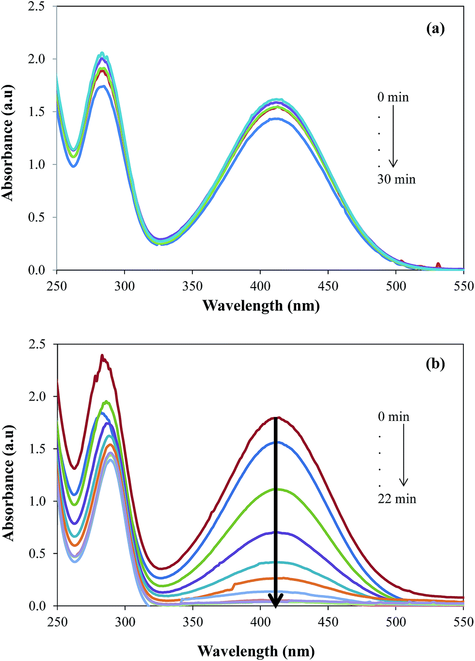
The catalytic activity was evaluated by employing the prepared GO–Au nanocomposite as catalyst for the reduction of 2-NA and then most importantly for the simultaneous reduction of dyes and 2-NA. Nitro compounds are supposed to be very toxic and they are discharged as wastes directly into water from many industries and thus their elimination or the conversion into useful product is essential.51 Due to the importance of degradation of nitro compounds, 2-NA was chosen as a model nitro compound to investigate the catalytic efficiency of GO–Au nanocomposite. The reduction of 2-NA was observed by UV-vis spectrophotometer in terms of decease in the absorbance at the absorption maxima of 410 nm. Initially, the reduction of 2-NA was studied in the presence of only NaBH4 and it was observed that only very negligible amount of nitro compound undergo reduction to corresponding amine as shown in Fig. 7(a).
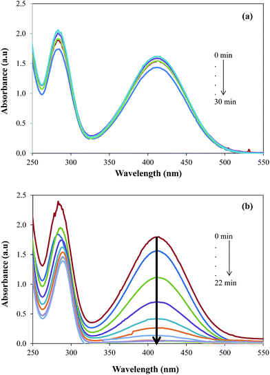 |
| | Fig. 7 UV-vis absorption spectra for the gradual reduction of 2-nitroaniline (a) in the absence of catalyst (b) in the presence of catalyst. Reaction conditions; 0.5 mM aqueous solution of 2-nitroaniline = 50 ml, NaBH4 = 0.1 g, graphene oxide–gold catalyst = 5 mg, 30 °C, 100 rpm. | |
Actually, there is a large kinetic barrier of activation energy for the reduction of 2-NA and direct interaction of 2-NA with NaBH4 cannot generate sufficient energy to overcome that energy barrier. However, the aid of a suitable catalyst can speeds up the reduction of 2-NA by providing a new reaction rout with lower activation energy. Therefore, upon the addition of GO–Au nanocomposite along with 4-NA and NaBH4, the reduction rate of 2-NA was significantly increased as shown by the decrease in absorption intensity of 2-NA at 410 nm in Fig. 7(b). As the reaction was carried out in large excess of NaBH4, the pseudo first order kinetics model as employed for the evaluation of rate constants.51–53 The pseudo first order kinetic equation can be written as:
where,
Co (mM) is the initial concentration of 2-NA,
Ct (mM) is the concentration of 2-NA at time
t and
kapp is apparent rate constant.
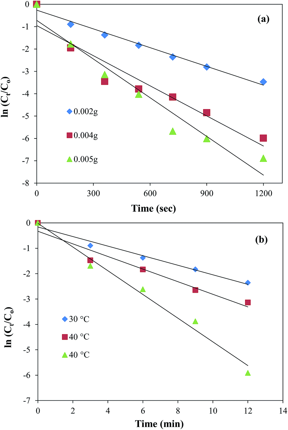
It can be seen from the Fig. 8(a) that the plots of ln(Ct/Co) against time give straight lines for the three different amounts of catalyst (0.002 g, 0.004 g, and 0.005 g). The increase in slope of the plots and hence the increase in the values of kapp from 2.8 × 10⁻³ to 5.8 × 10⁻³ s−1 was observed with the increase in catalyst amount from 0.002 g to 0.005 g. This increase is obvious as the presence of larger active catalytic sites increases the effective collision frequency and hence the rate of reaction increases. This variation in reduction rate with the catalyst amount is an important tool to control the reduction of nitro compounds. The maximum value of kapp was found to be 5.8 × 10⁻³ s−1 in the present work which is greater than previously reported by Cheng et al. for the catalytic reduction of 4-NP using GO based nanocatalyst.22 The effect of temperature on the catalytic activity of Au nanoparticles containing graphene composite was also studied by carrying out the reduction reaction at 3 different temperatures i.e., 30 °C, 40 °C and 50 °C keeping all other parameters constant. From the Fig. 8(b) it is clear that a good linear pattern of the plots of ln(Ct/Co) verses time was observed at all temperatures. Also, an increase in the slope and hence in the value of kapp from 2.8 × 10⁻³ to 4.2 × 10⁻³ s−1 was also observed with the increase in temperature from 30 to 50 °C. This increase in reduction rate with the increase in temperature is attributed to the increase in average kinetic energy of the reactants which in turn increases the rate of effective collisions between reactant molecules. The uniformity in linear trend also demonstrates the homogenous distribution of Au nanoparticles over the surface of GO sheets.54 The experimental data obtained from the effect of temperature on the reduction rate was further utilized to calculate the activation energy (Ea) of the reaction. The activation energy value was obtained by plotting lnkapp verses 1/T according to linear form of Arrhenius equation as shown in the ESI Fig. S8† and it was found to be 15.11 kJ mol−1.
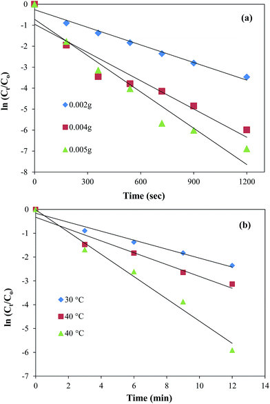 |
| | Fig. 8 Dependence of kapp on (a) the amount of catalyst at 30 °C and (b) temperature. Reaction conditions; 0.5 mM aqueous solution of 2-nitroaniline = 50 ml, NaBH4 = 0.1 g, graphene oxide–gold catalyst = 5 mg, 100 rpm. | |
Most importantly, the catalyst system was used for simultaneous degradation of mixture of dyes and aromatic compound present in the same reaction mixture. The ability of a catalyst to catalyse the degradation of a variety of contaminants increases its worth because the rapid degradation of multiple pollutant simultaneously from industrial waste provide great advantage in terms of time, energy and labour with great economical benefits. The simultaneous catalytic reduction of EV and 2-NA is shown in Fig. 9. The change in physical state of the reaction mixture during the course of reaction is also depicted with digital camera images in Fig. 9(a). The images (1) and (2) are representing that before mixing EV and 2-NA were blue and yellow coloured, respectively. After mixing of aqueous solutions of EV and 2-NA, colour of the solution was turned to brownish as shown by camera image (3).
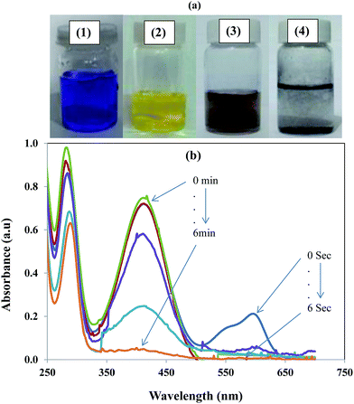 |
| | Fig. 9 (a) Photographs of aqueous solutions of (1) ethyl violet, (2) 2-nitroaniline, mixture of ethyl violet and 2-nitroaniline (3) before and (4) after catalytic reduction by using graphene oxide–gold nanocomposite as catalyst. (b) UV-vis absorption spectra showing the simultaneous reduction of ethyl violet dye and 2-nitroaniline in the presence of nanocatalyst. | |
When both the EV and 2-NA were simultaneously reduced then reaction mixture became colourless as shown by camera image (4) in Fig. 9(a). The UV-vis spectra in Fig. 9(b) represent the concurrent decrease in absorbance of EV and 2-NA during their simultaneous reduction. The degradation of EV was completed within 20 seconds while the complete reduction of 2-NA was occurred in almost 10 minutes.55 Therefore, it is obvious from the above results that this prepared nanocomposite has multiple benefits in the waste water treatment as it can eliminate/degrade multiple organic pollutants including cationic, dyes, anionic dyes and nitro aromatic compounds present in the same industrial effluent in a single step. It has been widely reported in literature that the reduction of aromatic nitro aromatic compounds at the surface of a nanocatalysts takes place via Langmuir Hinshelwood mechanism.56,57 So it was assumed that same reduction of 2-NA was also followed the same mechanism. The proposed mechanism for the reduction of 2-NA at the surface of Au nanoparticle is shown diagrammatically in Fig. 10. Both the reducing agent and 4-NP react at the surface of Au nanoparticles integrated in GO sheets. When NaBH4 is added in water, BH4− is produced which is strong nucleophile. Being a strong nucleophile, BH4− gives electron to catalyst and produce hydride ion. The hydride ions then react with proton (H+) provided by water to produce hydrogen molecules (H2). The H2 molecules are adsorbed at the surface of Au nanoparticles. The antibonding orbitals of the H2 molecules accept electron pairs from electron flow of catalyst and H2 molecules are converted into active hydrogen atoms which remain adsorbed at the surface of Au nanoparticles. The active hydrogen atoms then attack at the nitro group of 2-NA and reduce it via formation of intermediates containing nitroso (–NO) and hydroxylamino group (–NHOH). When 2-NA is reduced at the surface of Au nanoparticles, the formed product is desorbed from the surface of nanoparticle and in this way surface of nanoparticle is regenerated for further action.
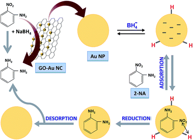 |
| | Fig. 10 Langmuir Hinshelwood mechanism for reduction of 2-nitroaniline on the surface of gold nanoparticles integrated on graphene oxide sheets. | |
Conclusions
GO–Au nanocomposite was prepared by a facile synthetic rout. The prepared nanocomposite was found as effective adsorbent for the removal of industrial dyes such as MO, MB and EV from aqueous atmosphere as well as efficient catalyst for the reduction of 2-NA. For the adsorption of EV and MB, adsorption isotherm and adsorption kinetics fitted well to Freundlich isotherm and pseudo-second order kinetics, respectively. Thermodynamics parameters showed that adsorption process was spontaneous and endothermic for both dyes. In addition, the prepared nanocomposite can also act as a catalyst with high catalytic efficiency for the reduction of 2-NA. Most importantly, the prepared nanocomposite showed simultaneous adsorption of mixture of dyes as well as simultaneous catalytic reduction of cationic dye and nitro aromatic compound. So, the findings of this work clearly highlight the superiority of the GO–Au nanocomposite absorbent/catalyst system over previous reports. Also, present study will gain an intensive attention for both the ground level research as well as technological application due to easy fabrication process and versatile performance of the product in waste water treatment and in catalysis. So, to view point of facile synthesis, better adsorption efficiency towards industrial dyes irrespective of their ionic nature, and good catalytic activity of GO–Au nanocomposite can be considered as economically very suitable adsorbent for the removal/catalytic reduction of dyes and nitro aromatic pollutants.
Conflicts of interest
There are no conflicts to declare.
References
- A. Kumar, G. Sharma, M. Naushad, S. Kalia and P. Singh, Ind. Eng. Chem. Res., 2014, 53, 15549 CrossRef CAS.
- M. A. Roosta, M. A. Ghaedi, N. Shokri, A. Daneshfar, R. Sahraei and A. Asghari, Spectrochim. Acta, Part A, 2014, 118, 55 CrossRef CAS.
- C. Kennes, E. R. Rene and M. C. Veiga, J. Chem. Technol. Biotechnol., 2009, 84, 1419 CrossRef CAS.
- G. M. Gadd, J. Chem. Technol. Biotechnol., 2009, 84, 13 CrossRef CAS.
- S. H. Jang, Y. G. Jeong, B. G. Min, W. S. Lyoo and S. C. Lee, J. Hazard. Mater., 2008, 159, 294 CrossRef CAS.
- L. Zhao and H. Mitomon, J. Appl. Polym. Sci., 2008, 110, 1388 CrossRef CAS.
- M. Naushad and Z. A. Alothman, Desalin. Water Treat., 2015, 53, 2158 CrossRef CAS.
- M. Naushad, Z. A. Alothman and G. Sharma, Ionics, 2015, 21, 1453 CrossRef CAS.
- Y. Yang, H. Liao, Z. Tong and C. Wang, Compos. Sci. Technol., 2015, 107, 137 CrossRef CAS.
- S. Wang and Y. Peng, Chem. Eng. J., 2010, 156, 11 CrossRef CAS.
- W. W. Ngah, L. C. Teong and M. A. K. M. Hanafiah, Carbohydr. Polym., 2011, 83, 1446 CrossRef.
- L. Meng, X. Zhang, Y. Tang, K. Su and J. Kong, Sci. Rep., 2015, 5, 7910 CrossRef CAS.
- M. Idrees, S. Batool, Q. Hussain, H. Ullah, M. I. Al-Wabel, M. Ahmad and J. Kong, Sep. Sci. Technol., 2016, 51, 2307 CrossRef CAS.
- D. Chen, H. Feng and J. Li, Chem. Rev., 2012, 112, 6027 CrossRef CAS.
- A. K. Geim and K. S. Novoselov, Nat. Mater., 2007, 6, 183 CrossRef CAS PubMed.
- P. Bradder, S. K. Ling, S. Wang and S. Liu, J. Chem. Eng. Data, 2010, 56, 138 CrossRef.
- X. Y. Pang and F. Gong, J. Chem., 2008, 5, 802 CAS.
- G. K. Ramesha, A. Vijaya Kumara, H. B. Muralidhara and S. Sampath, J. Colloid Interface Sci., 2011, 361, 270 CrossRef CAS.
- W. Zhao, Y. Tang, J. Xi and J. Kong, Appl. Surf. Sci., 2015, 326, 276 CrossRef CAS.
- L. Fan, C. Luo, M. Sun, X. Li, F. Lu and H. Qiu, Bioresour. Technol., 2012, 114, 703 CrossRef CAS.
- L. Fan, C. Luo, M. Sun, X. Li, F. Lu and H. Qiu, J. Hazard. Mater., 2012, 215, 272 CrossRef.
- Z. Cheng, J. Liao, B. He, F. Zhang, F. Zhang, X. Huang and L. Zhou, ACS Sustainable Chem. Eng., 2015, 3, 1677 CrossRef CAS.
- K. C. Hsu and D. H. Chen, Nanoscale Res. Lett., 2014, 9, 484 CrossRef.
- N. Li, M. Zheng, X. Chang, G. Ji, H. Lu, L. Xue, L. Pan and J. Cao, J. Solid State Chem., 2011, 184, 953 CrossRef CAS.
- W. Fan, W. Gao, C. Zhang, W. W. Tjiu, J. Pan and T. Liu, J. Mater. Chem., 2012, 22, 25108 RSC.
- L. Li, L. Fan, M. Sun, H. Qiu, X. Li, H. Duan and C. Luo, Colloids Surf., B, 2013, 107, 76 CrossRef CAS.
- B. K. Barman and K. K. Nanda, Chem. Commun., 2013, 49, 8949 RSC.
- H. Chen, M. B. Müller, K. J. Gilmore, G. G. Wallace and D. Li, Adv. Mater., 2008, 20, 3557 CrossRef CAS.
- L. Li, L. Fan, M. Sun, H. Qiu, X. Li, H. Duan and C. Luo, Int. J. Biol. Macromol., 2013, 58, 169 CrossRef CAS PubMed.
- M. Auta and B. H. Hameed, Chem. Eng. J., 2012, 198, 219 CrossRef.
- M. Auta and B. H. Hameed, Ind. Eng. Chem. Res., 2013, 19, 1153 CrossRef CAS.
- H. Karaer and I. Uzun, Desalin. Water Treat., 2013, 51, 2294–2305 CrossRef CAS.
- L. Ai, M. Li and L. Li, J. Chem. Eng. Data, 2011, 56, 3475–3483 CrossRef CAS.
- L. Ai, M. Li and L. Li, J. Chem. Eng. Data, 2011, 56, 3475–3483 CrossRef CAS.
- P. Sharma, N. Hussain, D. J. Borah and M. R. Das, J. Chem. Eng. Data, 2013, 58, 3477–3488 CrossRef CAS.
- T. Liu, Y. Li, Q. Du, J. Sun, Y. Jiao, G. Yang, Z. Wang, Y. Xia, W. Zhang, K. Wang and H. Zhu, Colloids Surf., B, 2012, 90, 197–203 CrossRef CAS.
- D. Wang, L. Liu, X. Jiang, J. Yu and X. Chen, Colloids Surf., A, 2015, 466, 166–173 CrossRef CAS.
- M. A. Salem, R. G. Elsharkawy and M. F. Hablas, Eur. Polym. J., 2016, 75, 577–590 CrossRef CAS.
- W. T. Tsai, Y. M. Chang, C. W. Lai and C. C. Lo, J. Colloid Interface Sci., 2005, 289, 333 CrossRef CAS.
- P. Sharma and M. R. Das, J. Chem. Eng. Data, 2012, 58, 151 CrossRef.
- X. Zhang, J. Liu, S. J. Kelly, X. Huang and J. Liu, J. Mater. Chem. A, 2014, 2, 11759 RSC.
- C. Ng, J. N. Losso, W. E. Marshall and R. M. Rao, Bioresour. Technol., 2002, 85, 131 CrossRef CAS.
- B. H. Hameed, D. K. Mahmoud and A. L. Ahmad, J. Hazard. Mater., 2008, 158, 65 CrossRef CAS.
- F. Bibi, M. Ajmal, F. Naseer and M. Siddiq, Int. J. Environ. Sci. Technol. DOI:10.1007/s13762-017-1446-4.
- L. Fan, C. Luo, M. Sun, X. Li, F. Lu and H. Qiu, J. Hazard. Mater., 2012, 215, 272 CrossRef PubMed.
- F. Liu, S. Chung, G. Oh and T. S. Seo, ACS Appl. Mater. Interfaces, 2012, 4, 922 CrossRef CAS PubMed.
- M. Ajmal, S. Demirci, Y. Uzun, M. Siddiq, N. Aktas and N. Sahiner, J. Colloid Interface Sci., 2016, 470, 39 CrossRef CAS.
- M. Ajmal, M. Siddiq, N. Aktas and N. Sahiner, RSC Adv., 2015, 5, 43873 RSC.
- K. Haubner, J. Morawski, P. Olk, L. M. Eng, C. Ziegler, B. Adolphi and E. Jaehne, ChemPhysChem, 2010, 11, 2131 CrossRef CAS.
- G. Z. Kyzas, E. A. Deliyanni and K. A. Matis, J. Chem. Technol. Biotechnol., 2014, 89, 196 CrossRef CAS.
- S. J. Hoseini, M. Rashidi and M. Bahrami, J. Mater. Chem., 2011, 21, 16170 RSC.
- L. Zhou, C. Gao and W. Xu, Langmuir, 2010, 26, 11217 CrossRef CAS.
- S. K. Ghosh, M. Mandal, S. Undu, S. Nath and T. Pal, Appl. Catal., A, 2004, 268, 61 CrossRef CAS.
- F. Lin and R. Doong, J. Phys. Chem. C, 2011, 115, 6591 CrossRef CAS.
- M. Ajmal, M. Siddiq, H. Al-Lohedan and N. Sahiner, RSC Adv., 2014, 103, 59562 RSC.
- Z. H. Farooqi, K. Naseem, R. Begum and A. Ijaz, J. Inorg. Organomet. Polym., 2015, 25, 1554 CrossRef CAS.
- R. Begum, R. Rehan, Z. H. Farooqi, Z. Butt and S. Ashraf, J. Nanopart. Res., 2016, 18, 231 CrossRef.
Footnote |
| † Electronic supplementary information (ESI) available: Materials and methods used for the preparation of GO, GO–Au nanocomposite, the procedure for conducting adsorption and catalytic experiments. See DOI: 10.1039/c7ra12030c |
|
| This journal is © The Royal Society of Chemistry 2018 |
Click here to see how this site uses Cookies. View our privacy policy here. 
 Open Access Article
 This Open Access Article is licensed under a Creative Commons Attribution-Non Commercial 3.0 Unported Licence
 *a
*a