
 Open Access Article
 This Open Access Article is licensed under a Creative Commons Attribution-Non Commercial 3.0 Unported Licence
Synthesis of boron nitride nanotubes using an oxygen and carbon dual-free precursor
Saleem Abbas*a,
Aumber Abbasb,
Yang Huang*a,
Jing Lina,
Zhenya Liua,
Yi Fanga and
Chengchun Tang *a
*a
aSchool of Materials Science and Engineering, Hebei Key Laboratory of Boron Nitride Micro and Nano Materials, Hebei University of Technology, Tianjin 300130, P. R. China. E-mail: tangcc@hebut.edu.cn; huangyang@hebut.edu.cn; saleem_physics19@hotmail.com; Fax: +86-22-60202660; Tel: +86-22-60202660
bChemical Engineering and Advanced Materials, School of Engineering, Newcastle University, Newcastle upon Tyne, NE1 7RU, UK
First published on 23rd January 2018
Abstract
Boron nitride nanotubes (BNNTs) have attracted extensive research attention due to their intriguing properties and promising applications. However, the fundamental issue regarding the introduction of oxygen and carbon impurities into the final product remains a challenge. Herein, we utilized a novel precursor consisting of oxygen and carbon dual-free reactants (MgF2, NH4Cl, and B) for the synthesis of pure BNNTs. The MgCl2 intermediate species of magnesium acts as a catalyst, which prevents the oxidization of the product and has been proved to be the key factor for pure BNNTs growth.
Introduction
Boron nitride nanotubes (BNNTs), an emerging semiconductor, have attracted significant attention since their prediction in 1994.1,2 BNNTs have a structure analogous to that of carbon nanotubes (CNTs), but possess properties different from them in various aspects. BNNTs exhibit numerous intriguing properties, including superb elasticity and strength,3 wide band gaps (ca. 5.5 eV) independent of diameter and chirality,2 good thermal conductivity,4 brilliant resistance to oxidation,5 unique luminescence,6 and good biocompatibility.7 Therefore, BNNTs show great promise in numerous potential fields such as optical systems,8 electrical nano-devices,9 energy storage,10 nuclear reactor facilities,11 radiation shielding in space vehicles,11 and biomedical areas.12–14To date, various fabrication techniques, including chemical vapor deposition (CVD),15,16 ball milling,17,18 laser ablation,19 plasma jet,20,21 arc discharge,22 and boron ink painting,23,24 have been adopted for BNNT growth. However, there are several problems, such as very high fabrication temperatures (1100–2700 °C), dangerous chemicals, non-uniform size and diameter, amorphous structure, small aspect ratios, and most importantly, undesirable impurities in gas grown products, associated with these techniques.25,26 Thus, facile, convenient, and effective preparation approaches for BNNTs are highly desired for future developments and investigations on their properties and applications in diverse fields.
In general, when a carbon-containing precursor is used, the as-synthesized BNNTs may suffer from carbon contamination since carbon is the first solid phase to appear upon cooling the vapors containing boron, nitrogen, and carbon. Tang et al. have developed the boric oxide CVD (BOCVD) approach, which is known as a significant progress in the growth of carbon-free BNNTs.27 Mixtures of the oxides of B, Mg, Li, Ga, and other metals are used as precursors in this approach. The precursors are activated at temperatures >1300 °C by induction heating, and vapors of volatile B2O2 are generated. The B2O2 vapors are carried by Ar gas to interact with NH3 gas to generate BNNTs.27,28 Although carbon contamination can be effectively depressed, this approach requires a special vertically designed induction furnace having a high heating rate and large temperature gradient. The key problem with this approach is how to overcome the high equipment cost and prevent oxide contaminations, which are inevitably introduced due to the essentially used oxygen-containing precursors. Both carbon and oxygen are hard to be removed by post-synthesis treatment but can essentially influence the optical and electrical properties of BNNTs.
Herein, we report a simple methodology for the preparation of BNNTs using an inexpensive conventional horizontal tube furnace comprising an alumina ceramic tube chamber. We proposed a new route towards the synthesis of highly pure BNNTs based on a modified CVD method, namely the boron trifluoride CVD (BFCVD) method. As compared to the BOCVD method, we utilize oxygen and carbon dual-free reactants for the synthesis of BNNTs with high purity and high yield. The O-free reactants play a crucial role in the synthesis of BNNTs. The intermediates species of magnesium help with one dimensional growth which has been proved during the synthesis of one dimensional materials.29,30 The novel accessory in our approach is the O-free precursor, especially MgF2 and its intermediate species (MgCl2), which controls the formation of nanotubes, prevents oxidization, and may possibly improve chemical stability. The synthesized BNNTs have diameters in the range of 25–45 nm with lengths up to several microns, displaying high aspect ratios. The optical property studies indicate that the well-structured BNNTs show strong UV-emission centered at 335 nm. The synthesis of BNNTs with a nano-size diameter and utilization of their promising properties present great potential for their application in high performance composites and optoelectronic nano-devices.
Experimental
Synthesis of BNNTs
High quality BNNTs have been synthesized by CVD reaction of boron (B) powder with NH3. In a typical procedure, powders of B, MgF2 and NH4Cl were mixed in a ratio of 2![[thin space (1/6-em)]](https://www.rsc.org/images/entities/char_2009.gif) :2:1 and subjected to ball milling for 24 hours. The hybrid powder acquired from ball milling was employed in an alumina sample holder boat and placed in an alumina tube vacuum chamber by facing the open end of the tube opposite to the gas flow and the closed end was positioned at the center of the heating zone (Fig. 1). A nickel foil substrate was placed face down above the alumina boat containing the precursor, for the deposition and growth of BNNTs. After the ceramic alumina tube vacuum chamber was evacuated to ca. 30 mTorr, a pure NH3 gas flow was introduced into the chamber at the rate of 200 sccm. Subsequently, the reaction chamber was heated to 1350 °C for 4 h. Vapors consisting of sublimated boron trifluoride (BF3) were generated from the mixed powder of boron and MgF2 and reacted with NH3 gas to produce BNNTs. Detailed reactions are given in growth mechanism (will be discussed later). The covering of the boat is very crucial under these conditions for the reaction, as it prevents the vapors of boron species from escaping out before reacting with NH3 gas. After the reaction was carried out for 2 h, the furnace was cooled down to room temperature naturally. All the toxic exhaust during the running of the experiment was absorbed by the NaOH solution cooling trap system. Finally, the pure white product was obtained from the nickel substrate.
:2:1 and subjected to ball milling for 24 hours. The hybrid powder acquired from ball milling was employed in an alumina sample holder boat and placed in an alumina tube vacuum chamber by facing the open end of the tube opposite to the gas flow and the closed end was positioned at the center of the heating zone (Fig. 1). A nickel foil substrate was placed face down above the alumina boat containing the precursor, for the deposition and growth of BNNTs. After the ceramic alumina tube vacuum chamber was evacuated to ca. 30 mTorr, a pure NH3 gas flow was introduced into the chamber at the rate of 200 sccm. Subsequently, the reaction chamber was heated to 1350 °C for 4 h. Vapors consisting of sublimated boron trifluoride (BF3) were generated from the mixed powder of boron and MgF2 and reacted with NH3 gas to produce BNNTs. Detailed reactions are given in growth mechanism (will be discussed later). The covering of the boat is very crucial under these conditions for the reaction, as it prevents the vapors of boron species from escaping out before reacting with NH3 gas. After the reaction was carried out for 2 h, the furnace was cooled down to room temperature naturally. All the toxic exhaust during the running of the experiment was absorbed by the NaOH solution cooling trap system. Finally, the pure white product was obtained from the nickel substrate.
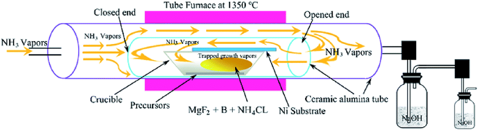 | ||
| Fig. 1 Schematic of the apparatus, reaction conditions and CVD process for the synthesis of BNNTs. | ||
Characterization
The surface morphology of the BNNTs was examined by high field scanning electron microscopy (HF-SEM, Hitachi SU-70). The microstructure of BNNTs was further investigated by bright field transmission electron microscopy (TEM) (JEOL, JEM-2100, Japan) and high-resolution transmission electron microscopy (HRTEM), combined with energy dispersive X-ray spectroscopy (EDX). Fourier transform infrared (FTIR) spectroscopy was carried out on a Nicolet 7100 spectrophotometer in the range of 400 to 4000 cm−1. Raman spectra were recorded on a Raman spectrometer using 532 nm excitation. The photoluminescence emission and excitation spectra were quantified using a Hitachi Fluorescence Spectrometer (F-7000).Results and discussion
A representative SEM image is shown in Fig. 2(a), which displays the morphology of the as grown BNNTs. They consist of wire-like one-dimensional nanostructures. The absence of any distinguishable impurity phases, such as bulk BN sheets/flakes, confirms the pure phase composition of the product. The diameter distribution of the BNNTs was carefully measured. The diameters of BNNTs measured from the SEM image are in the range of 25–45 nm, while the whole length reaches several microns, representing a high aspect ratios. The purity of BNNTs was further confirmed by EDX analysis. The EDX pattern in Fig. 2(b) shows the compositional analysis, mapping only boron and nitrogen atoms, indicating the high purity of the BNNTs. The copper and carbon signals come from the Holey carbon coated copper grid holding the specimen in TEM analysis.31–33 The absence of oxygen in the product indicates the strong capability of our method for the production of oxygen free BNNTs. | ||
| Fig. 2 (a) SEM image of the as-prepared BNNTs with uniform morphology, (b) EDX pattern displaying the high purity of BNNTs, (c) low magnification TEM image of a single BNNT and the corresponding high magnification image in the inset, (d) high resolution TEM (HRTEM) image of a typical BNNT clearly showing the layers of BN with an interplaner spacing of 0.34 nm, (e) SAED patterns of near arm-chair, and (f) near zig-zag BNNTs showing the lattice parameters of corresponding BNNTs. | ||
The microstructures and the inner morphology of the BNNTs were further investigated by TEM. Fig. 2(c) shows the low magnification TEM image of the BNNTs, showing the nanotubes crystallized as isolated tubules. The inset in Fig. 2(c) is the magnified image of a single nanotube clearly showing the high order cylindrical shape of the BNNTs. The magnified TEM image of a single nanotube maps an outer diameter of about 40 nm and an inner diameter of nearly 14.6 nm. In addition, the diameters of the individual nanotubes measured from different positions were almost same, showing a uniform and ordered structure of the as grown product. The HRTEM image depicted in Fig. 2(d) demonstrates the parallel and straight walled structure of the tube. HRTEM analysis shows an evidently resolved interplaner distance of 0.34 nm, which is the characteristic of the d002 spacing of the hexagonal BN (h-BN) network,34 indicating the highly crystalline structure of BNNTs.
The selected area diffraction (SAED) patterns of the as-synthesized BNNTs are presented in Fig. 2(e) and (f), showing the lattice parameters of the respective nanotubes, which further confirm their high crystallinity. Both near zig-zag and near arm-chair BNNTs were formed in our products. The SAED patterns (Fig. 2(e) and (f)) show the tube axis along the near zig-zag and the near arm-chair configurations.
The structural and electronic properties of the as prepared BNNTs were studied using Raman and FTIR spectroscopy (Fig. 3). A single sharp Raman peak is noticed at about 1370 cm−1, which corresponds to a well-known E2g in-plane vibrational mode of the h-BN network (Fig. 3(a)).35,36 It is interesting to note that no other significant peaks (especially at around 1580 cm−1 belonging to carbon)37,38 are detected, which further confirms the high purity of the as grown BNNTs. The FTIR spectra in Fig. 3(b) shows three obviously distinguishable adsorption peaks at 802, 1371 and 1516 cm−1. We correlate our FTIR spectrum with the ab initio calculations that illustrate the IR active modes by the zone folding method.39,40 Although these theoretical studies correspond with single wall tubes, our experimental findings represent that the effect of the multiwall nanotubes on phonon frequency is negligible. The adsorption bands at 1371 and 1516 cm−1 can be assigned to the in-plane stretching vibrations of h-BN. This phenomenon has been well explained by the zone folding method, which assumes the tubes as seamless cylinder-shaped rolls of BN films.39 The sharp peak at 1371 cm−1 is attributed to the transverse optical mode of the BN films, which vibrates along the tube axis or the longitudinal direction of the BNNTs.41
 | ||
| Fig. 3 (a) Raman spectroscopy of BNNTs showing a single strong peak at 1370 cm−1 corresponding to the E2g in-plane vibrational mode of BN, (b) FTIR spectroscopy of BNNTs displaying two peaks at 1371 cm−1 and 1516 cm−1 relating to the in-plane stretching mode, and third peak at 802 cm−1 attributed to the out-of-plane radical buckling mode of the BN network. | ||
The weak 1516 cm−1 band corresponds to the stretching vibration of the h-BN sheets along the tangential directions of BNNTs.16 This stretching vibration mode corresponds to a longitudinal optical mode of the h-BN that is Raman inactive. Interestingly, the longitudinal optical mode smoothens for the h-BN bulk material or thin sheets, and appears only when a strain is induced on the h-BN system by the tube curvature. Hence, we conclude that this longitudinal optical mode will be shown by highly crystalline BNNTs only, which is in good agreement with previous reports.16
The weak adsorption at 802 cm−1 is assigned to the out-of-plan radical buckling mode of the BN network, where B and N atoms move radically outward or inward.16,39 Low energy electron diffraction (LEED) studies and computational analysis have demonstrated that the B–N bonds in sp2 layered structures exhibit significant buckling.2,42 Displacement of the N atoms in the outward direction has been theoretically proposed and experimentally witnessed. This buckling becomes more obvious due to the curvature of BNNTs. Some sp3 admixture takes place in sp2 BN bonding as a result of this buckling structure, so that the softening of the FTIR vibrational modes can be perceived. Indeed, the B–N stretching vibrations perpendicular to the axis of the BNNTs show a shift in wavenumber by 9 cm−1 (from 811 to 802 cm−1) as compared to bulk h-BN, showing the buckled structure of BNNTs with strains induced on the cylindrical BN network.
Based on our experimental success, a mechanism for BNNTs growth is suggested. We present the reactions taking place during the synthesis of BNNTs based on our chemical thermodynamic calculations carried out with the help of FactSage 7.1 software. Four steps are proposed for the synthesis of BNNTs:
1. When the blended powder consisting of NH4Cl, MgF2 and B located in the alumina boat is heated in a tube furnace, NH4Cl dissociates into the vapors of NH3 and hydrogen chloride (HCl) at the temperature above 520 °C (the boiling point of NH4Cl) along with the reaction:
| NH4Cl (s) → NH3 (g) + HCl (g) |
The mixed vapors are prevented from escaping by the covering on the boat.
2. At sufficient vapor pressure, HCl vapors react with the MgF2 powder at high temperature to form MgCl2, and hydrogen fluoride (HF) vapors are generated as follows:
| 2HCl (g) + MgF2 (s) → MgCl2 (g) + 2HF (g) |
The produced intermediate species of magnesium, i.e. MgCl2, acts as a catalyst and plays a vital role during the growth process. Atomic collisions may take place to form small sized clusters of MgCl2. The formation of sufficient MgCl2 clusters maybe important, since a significant amount of the catalyst will be needed for achieving the required vapor pressure.
3. As HF vapors are very reactive, they react with boron powder to form BF3, which quickly starts vaporizing due to an elevated temperature.
| 6HF (g) + 2B (s) → 2BF3 (g) + 3H2 (g) |
4. Upon reaching significant vapor pressure, the vapors consisting of BF3 start reacting with the active sites on the surface of the catalyst species. This dissolution of boron species in the catalyst species takes place in the presence of NH3, causing supersaturation and leading to the precipitation of the BNNTs along with the reaction:
| BF3 (g) + NH3 (g) → BN (s) + 3HF (g) |
Melted particles of the catalyst are condensed on the nickel substrate when their partial vapor pressure is sufficient. Then the BN species diffuse into the condensed catalyst leading to supersaturation and subsequent precipitation of BNNTs. The incorporation of NH3 gas further enhances the growth process. The BNNTs are transported and deposited on the Ni substrate placed over the alumina boat. Finally, well defined BNNTs with diameter around 25–45 nm and length up to several microns are collected. We didn't find BNNTs at temperatures lower than 1350 °C. When the temperature is lowered to 1300 °C, the generation of BF3 vapors could still be realized but at a decreased rate. BNNTS couldn't be generated due to the insufficiency of BF3 vapors. Thus, we suggest that 1350 °C is the optimum temperature for the successful growth of BNNTs.
Our thermodynamic calculations indicate that vapors of MgCl2 and BF3 could exist at high vapor pressure. At reaction temperature, the vapors of MgCl2, BF3 and NH3 are essential for the growth of BNNTs. Thus, we believe that MgCl2, produced as an intermediate specie, serves as a catalyst during the growth process and is vaporized and removed at the end of reaction, as reported previously.29 In addition, the use of MgF2 is very important for the controlled release of MgCl2 vapors, and to control the vapor pressure of BF3 and MgCl2. If the vapor pressure is too high, the catalyst will easily grow up, leading to the failure of the growth of nanotubes. We did not find MgCl2 catalyst particles under electron microscopy because our synthesis temperature was very high (1350 °C), at which Mg and Cl couldn't survive15 and were evaporated. That is exactly why they were not detected in the TEM analysis. This is in good agreement with previous reports.15,29,43
The successful preparation of our highly crystalline BNNTs is based on the theory of nucleation.44,45 The probability of nucleation is given by following equation:
| PN = Aexp(−πσ2/k2T2lnα) |
In a chain of experiments with different amounts of precursor powders, it is proved that higher vapor pressures enhance the yield of BNNTs. It is worthy to note that the yield of BNNTs also increases when the combustion boat is porous from one side, or partially covered by the substrate. The little closed end alumina tube reactor and the substrate placed over the combustion boat help with the accumulation and trapping of growth vapors which react with NH3, resulting in the improved nucleation rate for BNNTs. Besides, the small alumina tube is placed in a large alumina tube with the open end facing opposite to the flow of NH3. Such a design prevents the direct contact of NH3 flow with the reaction zone and hinders the growth vapors from being carried out with gas before reaching the critical vapor pressure for effective nucleation of BNNTs. NH3 gas can easily diffuse from the open end of the tube into the reaction zone for the nucleation and growth of BNNTs.
BNNTs show distinctive luminescence properties based on their particular nanoscale structure. Fig. 4 shows the optical emission and excitation spectrum of BNNTs. Generally, the possibility of a substance to show luminescence relies on its intrinsic band edge structure and other intrinsic or extrinsic defects.46,47 The intense UV emission band recorded at around 330 nm has been described frequently for the bulk h-BN sheets and numerous nanostructures of BN.6,47–51 Therefore, the emission spectrum in Fig. 4 recorded at 335 nm comes from the nanotubes. This strong emission has been assigned to the defect associated sites (B or N vacancy defects) or intrinsic impurities in the BN network.
 | ||
| Fig. 4 Optical emission and excitation spectra of BNNTs. | ||
Relatively, a small emission peak recorded at ca. 227 nm could be analogous to the near-band-edge (NBE) exciton-related recombination in h-BN nanostructures.28 As illustrated previously, the purity and crystallinity of BN structures are the deciding factors for this emission band.52 A strong UV emission has been observed in highly crystalline h-BN nanostructures, for example, pure h-BN films or sheets53 and BN microtubes with good quality.52 However, this NBE emission could be perceived in most of the BN structures (e.g. nanoribbons,50 BOCVD–BNNTs,6 bamboo shaped nanotubes54) only at a very low temperature (100 or 4.2 K) and would disappear at room temperature. A deep UV-emission peak at 230 nm has only been reported for highly crystalline ultrafine BNNTs at room temperature.28 In this study, the NBE emission band observed at room temperature points out the reduced number of defects and, in turn, the high purity and crystallinity of our BNNTs relative to the other reported multi-walled nanotubes. These results imply that the as fabricated BNNTs have high crystallinity and demonstrate significant optoelectronic properties, which is critically important for their potential optoelectronic applications, especially in UV-range devices.
Conclusion
In summary, we presented an effective and facile strategy for the synthesis of BNNTs, via a novel precursor material. Pure and uniform BNNTs were obtained. For the first time, oxygen and carbon dual-free reactants were utilized for the fabrication of high quality BNNTs. The intermediate species (MgCl2) from MgF2 serves as a catalyst and plays a key role in the synthesis of BNNTs. The as-prepared BNNTs show strong UV-emission properties. The synthesis of BNNTs with uniform size distribution and high UV-emission show great potential for their application in composites and high performance optoelectronic devices. We strongly believe that this work will open the path towards next generation optoelectronic nanodevices.Conflicts of interest
There are no conflicts to declare.Acknowledgements
The authors gratefully acknowledge the financial support from the National Natural Science Foundation of China (51402086, 51372066, 51572068, 51772075), the Natural Science Foundation of Hebei Province (E2016202122, B2015202079), the Program for Changjiang Scholars and Innovative Research Team in University (PCSIRT: IRT13060), the Hundred Talent Program of Hebei Province (E2014100011), and the Innovation Fund for Excellent Graduate Student of Hebei Province (No. 220056).Notes and references
- A. Rubio, J. L. Corkill and M. L. Cohen, Phys. Rev. B: Condens. Matter Mater. Phys., 1994, 49, 5081–5084 CrossRef CAS.
- X. Blase, A. Rubio, S. G. Louie and M. L. Cohen, Europhys. Lett., 1994, 28, 335 CrossRef CAS.
- N. G. Chopra and A. Zettl, Solid State Commun., 1998, 105, 297–300 CrossRef CAS.
- Y. Xiao, X. H. Yan, J. X. Cao, J. W. Ding, Y. L. Mao and J. Xiang, Phys. Rev. B: Condens. Matter Mater. Phys., 2004, 69, 205415 CrossRef.
- D. Golberg, Y. Bando, K. Kurashima and T. Sato, Scr. Mater., 2001, 44, 1561–1565 CrossRef CAS.
- C. Zhi, Y. Bando, C. Tang, D. Golberg, R. Xie and T. Sekigushi, Appl. Phys. Lett., 2005, 86, 213110 CrossRef.
- X. Chen, P. Wu, M. Rousseas, D. Okawa, Z. Gartner, A. Zettl and C. R. Bertozzi, J. Am. Chem. Soc., 2009, 131, 890 CrossRef CAS PubMed.
- C. Zhi, Y. Bando, C. Tang, R. Xie, T. Sekiguchi and D. Golberg, J. Am. Chem. Soc., 2005, 127, 15996–15997 CrossRef CAS PubMed.
- W. Wang, Y. Bando, C. Zhi, W. Fu, E. Wang and D. Golberg, J. Am. Chem. Soc., 2008, 130, 8144–8145 CrossRef CAS PubMed.
- A. Siria, P. Poncharal, A.-L. Biance, R. Fulcrand, X. Blase, S. T. Purcell and L. Bocquet, Nature, 2013, 494, 455–458 CrossRef CAS PubMed.
- C. H. Lee, D. Zhang and Y. K. Yap, J. Phys. Chem. C, 2011, 116, 1798–1804 Search PubMed.
- G. Ciofani, V. Raffa, A. Menciassi and A. Cuschieri, Biotechnol. Bioeng., 2008, 101, 850–858 CrossRef CAS PubMed.
- X. Li, X. Wang, J. Zhang, N. Hanagata, X. Wang, Q. Weng, A. Ito, Y. Bando and D. Golberg, Nat. Commun., 2017, 8, 13936 CrossRef CAS PubMed.
- M. Emanet, Ö. Şen and M. Çulha, Nanomedicine, 2017, 12, 797–810 CrossRef CAS PubMed.
- C. Tang, Y. Bando, G. Shen, C. Zhi and D. Golberg, Nanotechnology, 2006, 17, 5882 CrossRef CAS.
- L. Wang, T. Li, X. Long, X. Wang, Y. Xu and Y. Yao, Nanoscale, 2017, 9, 1816–1819 RSC.
- Y. Chen, J. F. Gerald, J. S. Williams and S. Bulcock, Chem. Phys. Lett., 1999, 299, 260–264 CrossRef CAS.
- Y. Li, K. Zhao, S. Tung and E. Schneider, Mater. Lett., 2009, 63, 1733–1736 CrossRef CAS.
- D. P. Yu, X. S. Sun, C. S. Lee, I. Bello, S. T. Lee, H. D. Gu, K. M. Leung, G. W. Zhou, Z. F. Dong and Z. Zhang, Appl. Phys. Lett., 1998, 72, 1966–1968 CrossRef CAS.
- L. Han and P. Krstić, Nanotechnology, 2017, 28, 07LT01 CrossRef PubMed.
- C. M. Lee, S. I. Choi, S. S. Choi and S. H. Hong, Curr. Appl. Phys., 2006, 6, 166–170 CrossRef.
- A. Loiseau, F. Willaime, N. Demoncy, G. Hug and H. Pascard, Phys. Rev. Lett., 1996, 76, 4737 CrossRef CAS PubMed.
- L. Lu Hua, C. Ying and M. G. Alexey, Nanotechnology, 2010, 21, 105601 CrossRef PubMed.
- L. H. Li, Y. Chen and A. M. Glushenkov, J. Mater. Chem., 2010, 20, 9679–9683 RSC.
- D. Golberg, Y. Bando, Y. Huang, T. Terao, M. Mitome, C. Tang and C. Zhi, ACS Nano, 2010, 4, 2979–2993 CrossRef CAS PubMed.
- C.-Y. Su, W.-Y. Chu, Z.-Y. Juang, K.-F. Chen, B.-M. Cheng, F.-R. Chen, K.-C. Leou and C.-H. Tsai, J. Phys. Chem. C, 2009, 113, 14732–14738 CAS.
- C. Tang, Y. Bando and D. Golberg, J. Solid State Chem., 2004, 177, 2670–2674 CrossRef CAS.
- Y. Huang, J. Lin, C. Tang, Y. Bando, C. Zhi, T. Zhai, B. Dierre, T. Sekiguchi and D. Golberg, Nanotechnology, 2011, 22, 145602 CrossRef PubMed.
- C. Tang, Y. Bando, T. Sato and K. Kurashima, Chem. Commun., 2002, 1290–1291 RSC.
- S. Abbas, Y. Huang, J. Lin, A. Abbas, X. Xu, J. Li, S. Wang, X. Jin and C. Tang, RSC Adv., 2016, 6, 29818–29822 RSC.
- J. Li, H. Zeng, S. Sun, J. P. Liu and Z. L. Wang, J. Phys. Chem. B, 2004, 108, 14005–14008 CrossRef CAS.
- U. Mathis, R. Kaegi, M. Mohr and R. Zenobi, Atmos. Environ., 2004, 38, 4347–4355 CrossRef CAS.
- K. N. Yun, Y. Sun, J. S. Han, Y.-H. Song and C. J. Lee, ACS Appl. Mater. Interfaces, 2017, 9, 1562–1568 CAS.
- D. Golberg, Y. Bando, C. C. Tang and C. Y. Zhi, Adv. Mater., 2007, 19, 2413–2432 CrossRef CAS.
- X. Li, M. B. Jordan, T. Ayari, S. Sundaram, Y. El Gmili, S. Alam, M. Alam, G. Patriarche, P. L. Voss and J. P. Salvestrini, Sci. Rep., 2017, 7, 786 CrossRef PubMed.
- X. Chen, C. M. Dmuchowski, C. Park, C. C. Fay and C. Ke, Sci. Rep., 2017, 7, 11388 CrossRef PubMed.
- V. Parashar, C. P. Durand, B. Hao, R. G. Amorim, R. Pandey, B. Tiwari, D. Zhang, Y. Liu, A.-P. Li and Y. K. Yap, Sci. Rep., 2015, 5, 12238 CrossRef PubMed.
- V. K. Thakur, J. Yan, M.-F. Lin, C. Zhi, D. Golberg, Y. Bando, R. Sim and P. S. Lee, Polym. Chem., 2012, 3, 962–969 RSC.
- L. Wirtz, A. Rubio, R. A. de La Concha and A. Loiseau, Phys. Rev. B: Condens. Matter Mater. Phys., 2003, 68, 045425 CrossRef.
- L. Wirtz and A. Rubio, IEEE Trans. Nanotechnol., 2003, 2, 341–348 CrossRef.
- T. Chengchun, B. Yoshio, S. Guozhen, Z. Chunyi and G. Dmitri, Nanotechnology, 2006, 17, 5882 CrossRef.
- S. H. Lim, J. Luo, W. Ji and J. Lin, Catal. Today, 2007, 120, 346–350 CrossRef CAS.
- C. Tang, Y. Bando, Y. Huang, S. Yue, C. Gu, F. Xu and D. Golberg, J. Am. Chem. Soc., 2005, 127, 6552–6553 CrossRef CAS PubMed.
- S. L. Mensah, V. K. Kayastha, I. N. Ivanov, D. B. Geohegan and Y. K. Yap, Appl. Phys. Lett., 2007, 90, 113108 CrossRef.
- J. M. Blakely and K. A. Jackson, J. Chem. Phys., 1962, 37, 428–430 CrossRef CAS.
- B. K. Gupta, V. Shanker, M. Arora and D. Haranath, Appl. Phys. Lett., 2009, 95, 073115 CrossRef.
- P. Jaffrennou, J. Barjon, J. S. Lauret, A. Maguer, D. Golberg, B. Attal-Trétout, F. Ducastelle and A. Loiseau, Phys. Status Solidi B, 2007, 244, 4147–4151 CrossRef CAS.
- L. Museur, D. Anglos, J.-P. Petitet, J.-P. Michel and A. V. Kanaev, J. Lumin., 2007, 127, 595–600 CrossRef CAS.
- P. Jaffrennou, J. Barjon, T. Schmid, L. Museur, A. Kanaev, J. S. Lauret, C. Y. Zhi, C. Tang, Y. Bando and D. Golberg, Phys. Rev. B: Condens. Matter Mater. Phys., 2008, 77, 235422 CrossRef.
- Z.-G. Chen, J. Zou, G. Liu, F. Li, Y. Wang, L. Wang, X.-L. Yuan, T. Sekiguchi, H.-M. Cheng and G. Q. Lu, ACS Nano, 2008, 2, 2183–2191 CrossRef CAS PubMed.
- P. Jaffrennou, J. Barjon, J. S. Lauret, B. Attal-Trétout, F. Ducastelle and A. Loiseau, J. Appl. Phys., 2007, 102, 116102 CrossRef.
- Y. Huang, Y. Bando, C. Tang, C. Zhi, T. Terao, B. Dierre, T. Sekiguchi and D. Golberg, Nanotechnology, 2009, 20, 085705 CrossRef PubMed.
- K. Watanabe, T. Taniguchi and H. Kanda, Nat. Mater., 2004, 3, 404–409 CrossRef CAS PubMed.
- P. Jaffrennou, F. Donatini, J. Barjon, J. S. Lauret, A. Maguer, B. Attal-Trétout, F. Ducastelle and A. Loiseau, Chem. Phys. Lett., 2007, 442, 372–375 CrossRef CAS.
| This journal is © The Royal Society of Chemistry 2018 |