
 Open Access Article
 This Open Access Article is licensed under a
 Creative Commons Attribution 3.0 Unported Licence
Sealing of anodized magnesium alloy AZ31 with MgAl layered double hydroxides layers†
Gen Zhanga,
Liang Wu *ab,
Aitao Tang*ab,
Bo Wengc,
Andrej Atrensd,
Shida Maa,
Lei Liua and
Fusheng Panab
*ab,
Aitao Tang*ab,
Bo Wengc,
Andrej Atrensd,
Shida Maa,
Lei Liua and
Fusheng Panab
aCollege of Materials Science and Engineering, Chongqing University, Chongqing 400044, China. E-mail: wuliang@cqu.edu.cn; tat@cqu.edu.cn; Tel: +86 17783101968 Tel: +86 23 65106121
bNational Engineering Research Center for Magnesium Alloys, Chongqing University, Chongqing 400044, China
cChongqing Key Lab for Advanced Materials & Clean Energies of Technologies, Institute for Clean Energy and Advanced Materials, Southwest University, Chongqing 400715, China
dSchool of Mechanical and Mining Engineering, The University of Queensland, Brisbane, Qld 4072, Australia
First published on 9th January 2018
Abstract
In this work, anodized magnesium alloy AZ31 with and without boiling water sealing was pre-prepared, and then MgAl-layered double hydroxide (LDH) films were fabricated on it through hydrothermal chemical conversion of the pre-prepared anodic layer. The morphology, structure, and composition of the films were characterized by XRD, SEM, EDS, FT-IR, XPS and GDOES. It was found that the porosity of the films was reduced after in situ fabrication of the LDHs. The effects of boiling water sealing treatment on the anodized substrate were also discussed. Moreover, the polarization curve, EIS, and immersion tests showed that LDHs fabricated on the anodized substrate with boiling water sealing treatment exhibited a significant long period of protection for the substrate.
1. Introduction
Magnesium alloys, as the lightest structural metal, are increasingly being considered as an alternative to other metallic structural engineering materials. Unfortunately, their highly reactive nature and low corrosion resistance inhibit their wide scale use in many applications.1,2 To date, a variety of methods have been proposed and developed to protect magnesium alloys from corrosion. Examples including, purification of magnesium alloys, homogenization of microstructure and addition of rare earth elements3–5 are metallurgical methods to improve the corrosion resistance of Mg-based alloys. However, protection against general corrosion and galvanic corrosion remains a great challenge. Therefore, surface treatments including anodizing, conversion films, vapor deposition, flame or plasma spraying are considered to be other approaches to improve corrosion resistance.6–8As an industrial technology for surface protection, the anodizing process has been successfully used over many decades.9 Nevertheless, the structures of anodic films consist of an inner thin compact layer and an outer thick porous layer. Although the porous structure is conducive to be coloured by organic dyes or inorganic pigments, porous anodic layers are defects, which reduce the corrosion resistance or even accelerate the corrosion damage of the substrate.10 Consequently, a sealing treatment is a necessary step after anodizing to enhance corrosion protection. The most common sealing treatments are conducted using boiling water, silicates, sol–gel and polymer coatings.11–14
Recently, conversion films also have been widely studied since they are inexpensive and simple.9 Layered double hydroxides (LDHs) as a chemical conversion film have been developed to improve the corrosion resistance of the metallic substrate. LDHs are a class of two-dimensional nanostructured anionic clays, with a structure that can be described as a brucite-like layer, and by the general formula of [M(II)1−xM(III)x(OH)2][An−]x/n·mH2O, where M(II) and M(III) are divalent and trivalent metal cations, respectively, and An− are interlayer charge-compensating anions. Based on their ion-exchange capability, the LDHs can act as nanotraps that release interlayer anions and store corrosion-relevant anions such as chlorides. As a result, LDHs can delay the diffusion of ‘aggressive’ ions to the metallic substrate surface.15,16
Previous studies15–18 used coprecipitation to prepare LDHs. One major disadvantage of coprecipitation is the poor adhesion between the film and the substrate compared to other methods. Moreover, this methodology is complex, time consuming, poorly crystallized and produces large amounts of wastes.19,20 The steam7,21,22 is also a common method to synthesize LDHs, but is accompanied with the low content of LDHs, even with no LDH ingredient.
Compared to these methods, the in situ method directly grows films on the metal substrate. This can also considerably improve the adherence to the substrate and the mechanical stability of the film.23 Furthermore, although the film does not consist of a single LDH phase, the amount of the impurity phase is low. Tedim and colleagues24–26 prepared ZnAl-LDHs on aluminium alloys using a Zn2+ containing aqueous solution. They found that the surface of the metal was covered by a thin film separated by micro-metre sized islands where the LDHs were concentrated. They demonstrated that a relatively high dissolution of Al3+, which came from the intermetallics, promoted the preferential growth of LDHs in the area of the intermetallic phases. Nevertheless, the surface could not be completely covered by LDHs because of the island structure, which was not good for the long-term protection of the metallic substrate. Wu et al.27 reported a electrochemical deposition method for preparing ZnAl-LDHs on magnesium alloys. Zhou et al.28 developed a ZnAl-LDHs nitrate on the magnesium alloy by immersion of Mg sheets in Zn and Al containing solution, and was then intercalated with Cl− and VO3− respectively. They found that the concentration gradient wall of chloride anions in LDHs chloride films successfully delayed the diffusion of aggressive chloride ions to the magnesium alloy surface and LDHs vanadate films not only absorbed aggressive chloride ions but also released vanadate anions in solution.
In several recent studies, LDH films were prepared on an anodized aluminium alloy rather than directly on the bare metallic substrate.29–31 On the one hand, the pores were sealed by LDHs, which were formed on the anodic layers. On the other hand, the thin compact inner layer of the anodic film, and the LDH films with the high density, could stop ‘aggressive’ ions from reaching the metallic substrate. Furthermore, Li30 and Kuznetsov31 studied the difference of LDH films formed on anodized aluminium alloy with and without boiling water sealing. They found that the growth of LDHs was greatly influenced by the boiling water sealing treatment on the anodized aluminium alloy. A more compact arrangement of LDH nanosheets could be gained by this method. However, the mechanism of the boiling water sealing for anodized aluminium alloy on the growth of LDHs was not thoroughly analysed. And, there are few publications reporting the formation of LDHs on anodized magnesium alloys. Moreover, Chen et al.32 believed that the amount of Al, which was dissolved from the Mg alloys of low Al content, such as AZ31, was far from sufficient for the formation of MgAl-LDH films. Thus, it is necessary to add Al containing compounds to the precursor solution for the synthesis of LDHs. Nevertheless, such metal solution is acidic due to the hydrolysis of the metal salt, and the pH of the solution must be adjusted for the synthesis of the LDHs.
In this study, the magnesium alloy AZ31 was anodized in a solution of NaOH and NaAlO2. The Al could enter into the anodic films from the anodizing solution. The anodic films, including enough Mg and Al mixed oxide, could act as the internal source of divalent and trivalent metal cations to prepare the LDHs. LDHs were prepared in deionized water only without adding extra salts in this novel method. And, the influence of boiling water sealing treatment on the growth of LDHs was also studied. The structure, morphology and corrosion behavior of the LDH films were investigated by physical, chemical and electrochemical methods.
2. Experimental methods
2.1 Materials
The cast magnesium alloy AZ31 was used as the substrate, with the following nominal composition in wt%: Al 2.5–3.5, Zn 0.6–1.3, Mn 0.2–1, Ca 0.04, Si 0.1, Cu 0.05, and balance Mg. All reagents were analytically pure and were used as raw materials without further purification. Deionized water was used as a solvent.2.2 Anodizing and sealing
Samples of 10 × 10 × 5 mm and 20 × 20 × 5 mm size were ground to 2000 grit SiC paper, then were anodized in a solution of 7.14 g L−1 NaOH and 4 g L−1 NaAlO2 for 30 min with an applied voltage of 20 V, ultrasonically cleaned in ethyl alcohol for 5 min, and dried under a steam of air.After anodizing, some samples were sealed in boiling water at atmospheric pressure for 20 min. Similarly, some samples were dried under a steam of air.
2.3 Preparation of LDHs
To prepare MgAl-LDHs, the samples were immersed vertically in deionized water and heated in a Teflon-lined autoclave at 398 K for 12 h. This method does not introduce any kinds of metal salts. The preparation conditions of the different samples are summarized in Table 1. For clarity of discussion, anodized substrates without and with boiling water sealing were denoted as A and AS respectively. Furthermore, LDHs fabricated on anodized substrates with and without boiling water sealing were denoted as A-LDH and AS-LDH respectively.| Sample | Anodizing | Pre-treatment | Post-treatment |
|---|---|---|---|
| Sealing | Preparation of LDHs | ||
| A | + | − | − |
| AS | + | + | − |
| A-LDH | + | − | + |
| AS-LDH | + | + | + |
2.4 Characterization
The surface and cross-sectional morphologies of the as-prepared samples were observed using a field-emission scanning electron microscope (FE-SEM; Nova 400 FEI, USA). For cross-sectional examinations, sections of the samples were generated by ultramicrotomy (UC; Leica EM UC7, Germany) using a diamond knife. The chemical composition was investigated using energy dispersive spectra (EDS; INCA Energy 350 Oxford, UK) and X-ray photoelectron spectroscopy (XPS; ESCALAB 250Xi, USA) with Al Kα radiation (1486.6 eV). The analyzed area for XPS was about 25 mm2 at the center of the surface of samples. Fourier-transform infrared (FT-IR; Nicolet IS5 Thermo Scientific, USA) attenuated total reflection spectroscopy (ATR) was obtained in the wavenumber range of 4000–400 cm−1. Glow discharge optical emission spectroscopy (GDOES; GD Profile 2, French) depth profile analysis of the films was carried out at a pressure of 700 Pa and at power of 40 W. The structures of the obtained LDH films were examined using an X-ray diffractometer (XRD; D/Max 2500X Rigaku, Japan) at a glancing angle of 1.5° using a Cu target (40 kV, 150 mA), within the range of 2θ = 5–80° and at a scanning rate of 4° min−1.The electrochemical impedance spectra (EIS) and potentiodynamic polarization curves (PDP) were obtained using a CIMPS-2 Zahner system. A classical three-electrode system was used in this experiment. The sample was the working electrode (1 cm2), a saturated calomel electrode (SCE) was used as the reference electrode, and a platinum plate was used as the counter electrode. Impedance measurements were performed from 10 mHz to 100 kHz using a 10 mV rms sinusoidal perturbation. 10 experimental points were collected per frequency decade above 66 Hz and 5 experimental points were collected below 66 Hz. The experimental impedance plots were fitted using different equivalent circuits by means of the Zview software. The polarization curves was measured at a scan rate of 2 mV s−1. Each polarization curve was measured three times. All the spectra were recorded at open circuit potential. All polarization tests, EIS tests and immersion tests were carried out at room temperature.
3. Results and discussion
3.1 Film morphology and composition
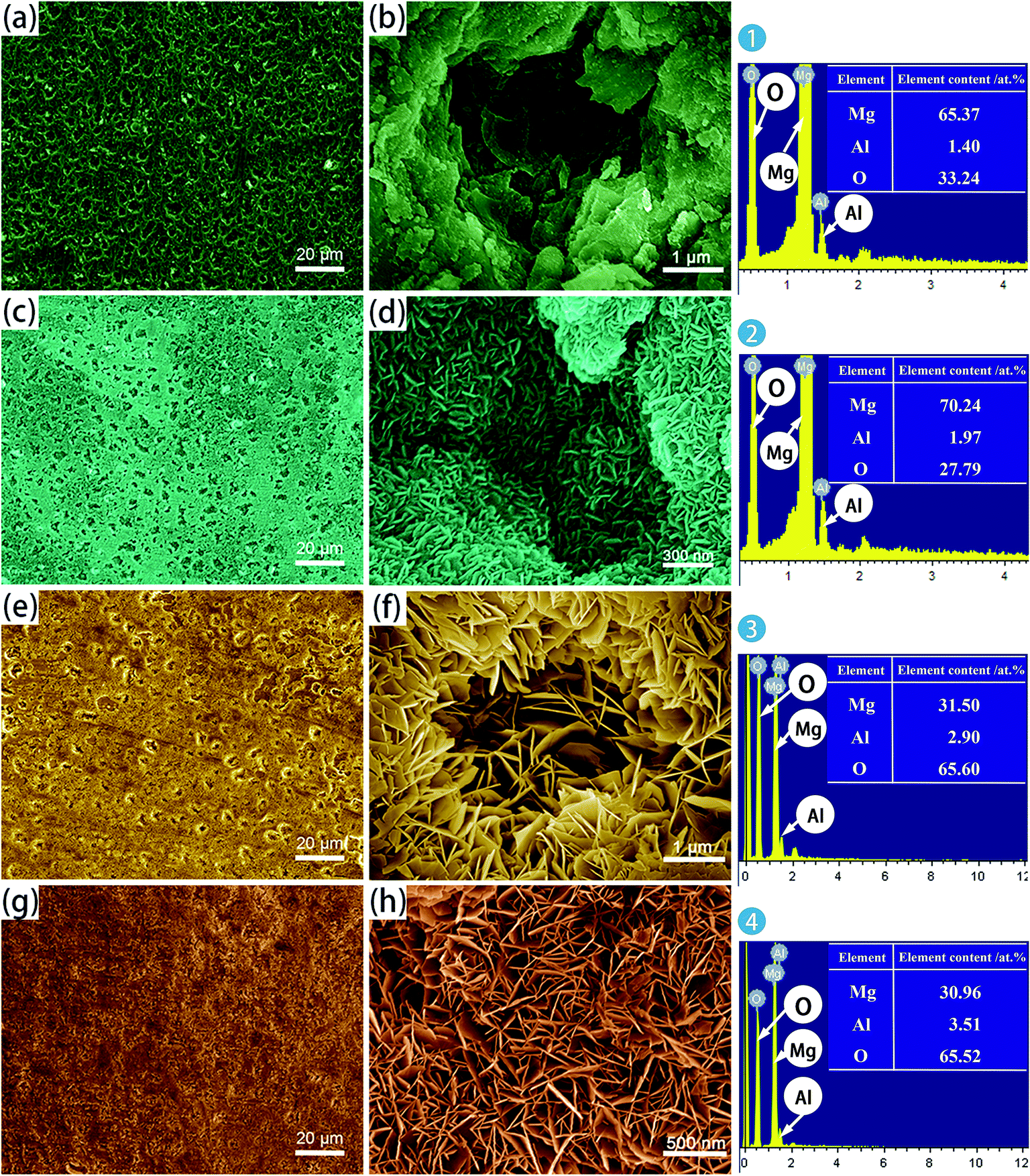 | ||
| Fig. 1 SEM surface micrographs and EDS analysis of: (a and b) A; (c and d) AS; (e and f) A-LDH; (g and h) AS-LDH. | ||
After the LDH-sealing, the porosity of the films was reduced but pores still existed as shown in Fig. 1e. The high resolution SEM images indicated that the pores were covered with LDHs. The porosity of the film on the AS-LDH sample was significantly reduced, and the surface of films had become smoother. This could be attributed to the in situ fabrication of fine and compact LDH nanosheets. Fig. 1h indicates that the flake-like nanosheets interlace each other and were just like a nest. In addition, EDS data showed that the A-LDH and AS-LDH samples also contained Mg, Al and O. But the ratios of the elements were different from that of A and AS, indicating that phase transitions occurred after the in situ fabrication of LDHs. The higher Al/Mg ratio of AS-LDH compared with that of A-LDH indicates the formation of more stable and a larger quantity of interlayer molecules.34
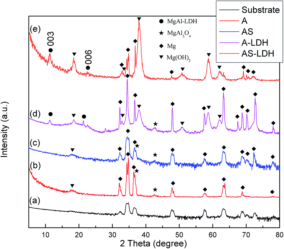 | ||
| Fig. 2 XRD patterns of (a) the substrate; (b) A; (c) AS; (d) A-LDH; (e) AS-LDH. | ||
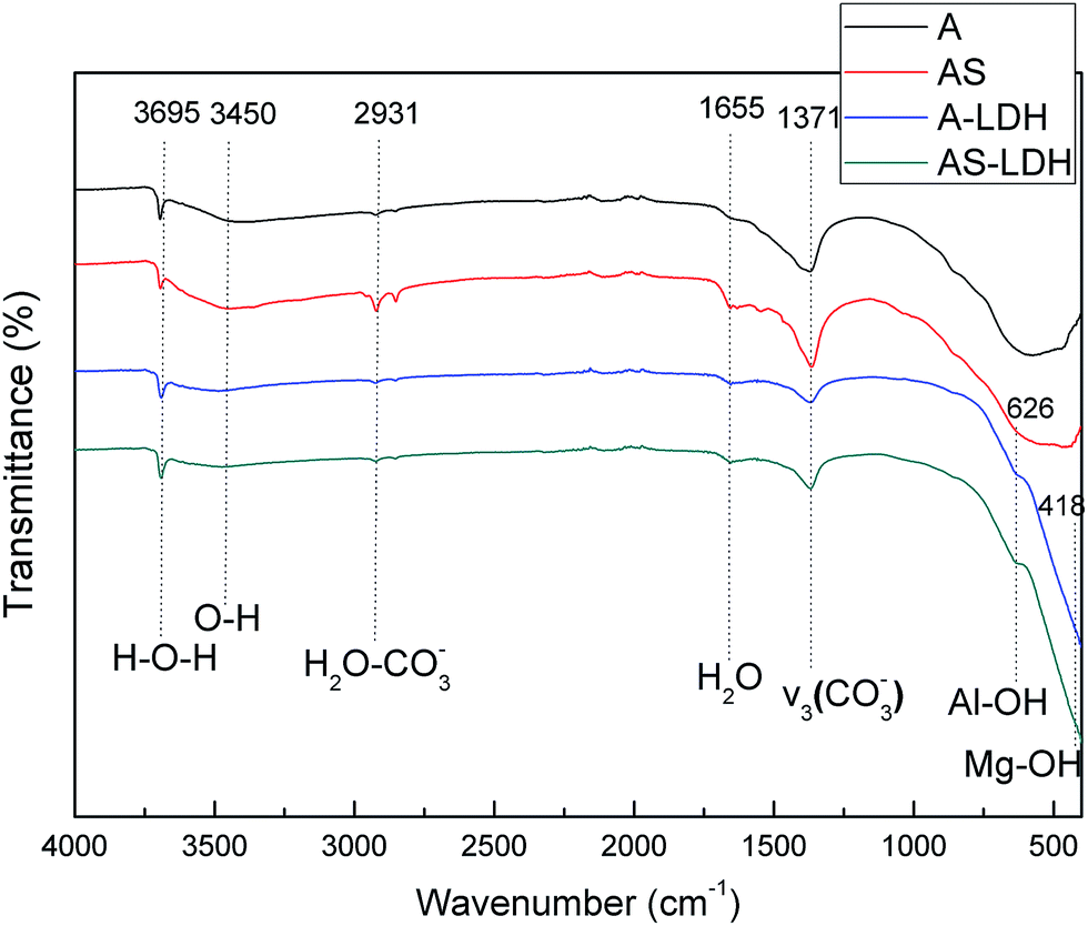 | ||
| Fig. 3 FT-IR spectra of A, AS, A-LDH and AS-LDH. | ||
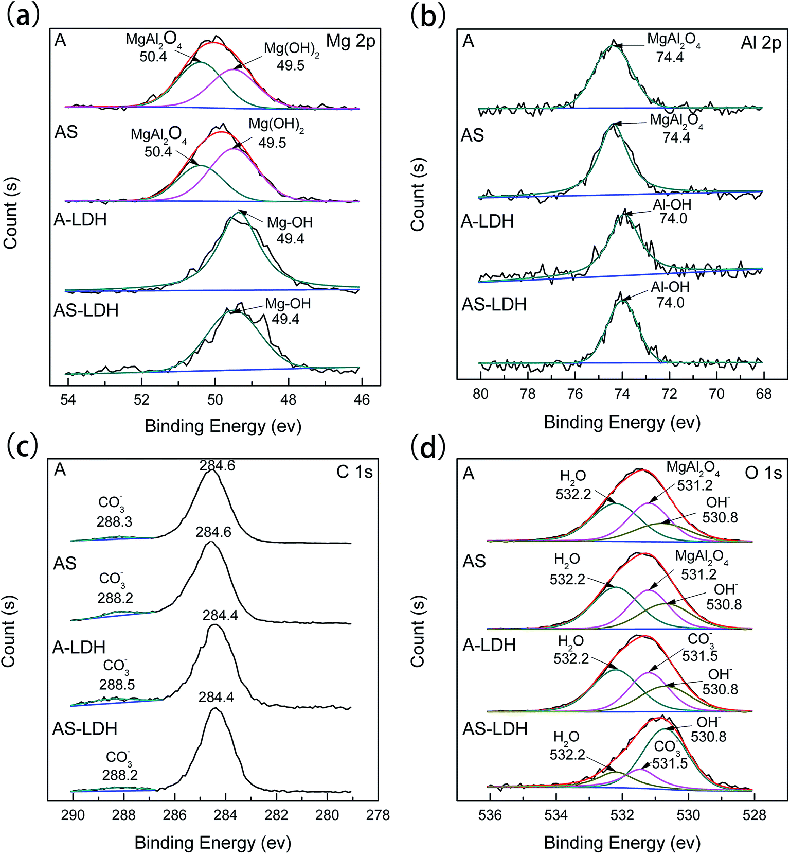 | ||
| Fig. 4 XPS analysis for (a) Mg 2p, (b) Al 2p, (c) C 1s, (d) O 1s spectrum of the different samples. | ||
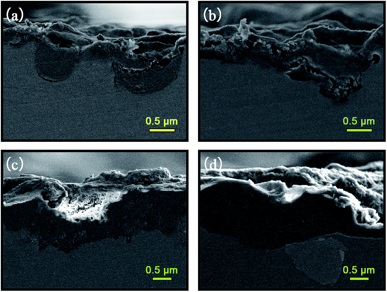 | ||
| Fig. 5 Cross-sectional SEM micrographs of (a) A; (b) AS; (c) A-LDH; (d) AS-LDH. | ||
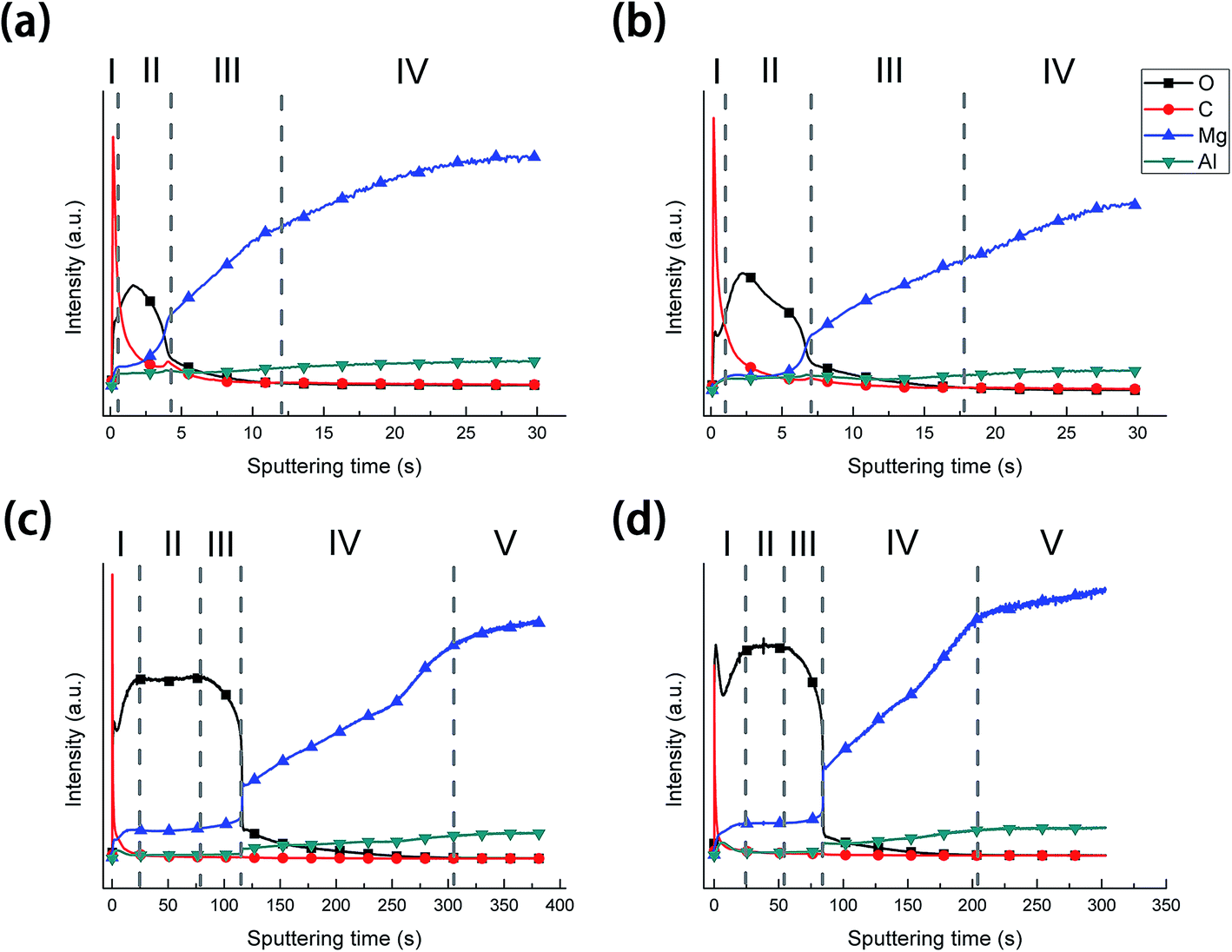 | ||
| Fig. 6 GDOES depth profile of samples: (a) A; (b) AS; (c) A-LDH; (d) AS-LDH. | ||
3.2 Corrosion resistance of the films
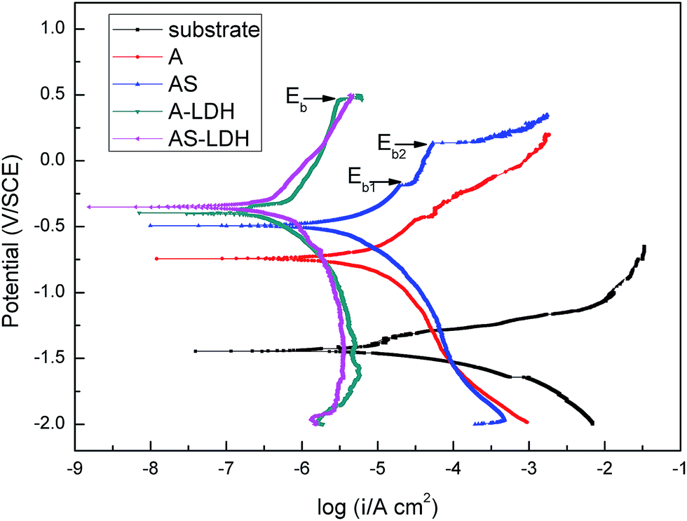 | ||
| Fig. 7 Tafel polarization curves in 3.5 wt% NaCl solution of A, AS, A-LDH and AS-LDH. | ||
| Sample | Ecorr (VSCE) | icorr (μA cm−2) | Tafel slope (mV dec−1) | Pi (mm per year) | |
|---|---|---|---|---|---|
| ba | bc | ||||
| Substrate | −1.32 ± 0.31 | 12.3 ± 2.21 | 153 | −76 | 0.28 |
| A | −0.76 ± 0.02 | 4.34 ± 0.45 | 416 | −320 | 0.10 |
| AS | −0.46 ± 0.03 | 2.85 ± 0.49 | 434 | −437 | 0.07 |
| A-LDH | −0.36 ± 0.09 | 0.84 ± 0.32 | 810 | −533 | 0.02 |
| AS-LDH | −0.29 ± 0.06 | 0.35 ± 0.03 | 622 | −581 | 0.01 |
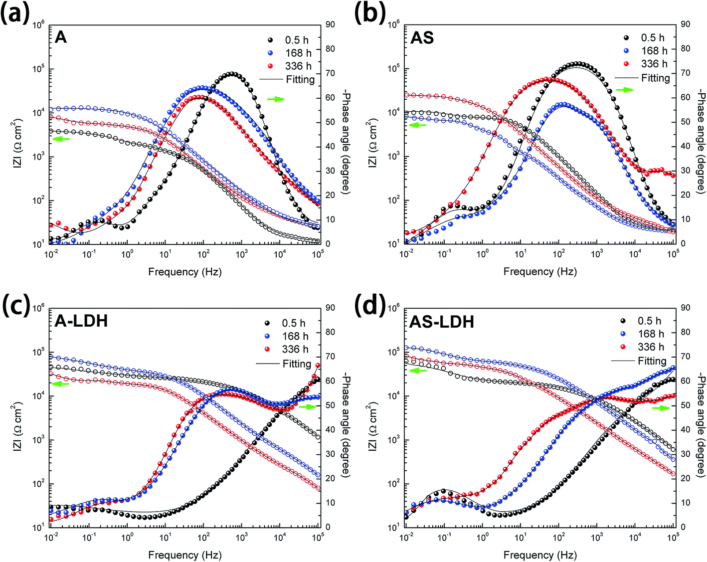 | ||
| Fig. 8 Bode representations of EIS spectra of (a) A; (b) AS; (c) A-LDH; (d) AS-LDH during immersion in 3.5 wt% NaCl solution. | ||
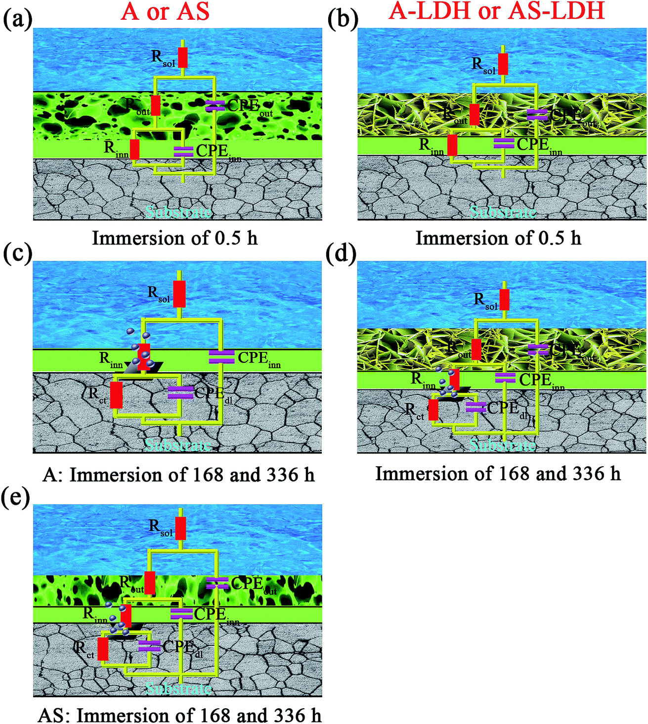 | ||
| Fig. 9 Equivalent circuits used to fit EIS plots and physical models. | ||
For longer immersion time (168 h), the anodized substrate (A) also shows two time constants, while the other samples show the appearance of a third relaxation process. This difference may attribute to outer layer dissolution of the anodic films. As a result, the first time constants can be attribute to an inner layer of the anodic films while the second is associated with the corrosion process. Its physical model and corresponding equivalent circuit are shown in Fig. 9c. Meanwhile, physical models and corresponding equivalent circuits shown in Fig. 9d and e can be used to model the corrosion processes and fit the EIS data for AS, A-LDH and AS-LDH. Rct represent the resistance of charge transfer; CPEdl describe constant phase elements of double layer.
After a longer immersion (336 h), AS, A-LDH and AS-LDH all also show three time constants, the first at high frequencies, the second at intermediate frequencies and the third at low frequencies, which are attributed to the LDHs layer (or the outer layer of the anodic films), the inner layer of anodic films and the corrosion process, respectively. This response can also be fitted to the equivalent electric circuit shown in Fig. 9d and e.
Fig. 10 presents the evolution of the outer layer (Rout), inner layer (Rinn) and charge-transfer resistance (Rct) for the different samples obtained by fitting the EIS data. Anodic films show resistances of the outer layer for low immersion times (t < 84 h), but this response is no longer detected for longer immersion times. Furthermore, this result proves that the anodic films cannot effectively protect the substrate from corrosion in an aggressive environment for a longer period without the sealing treatment. The resistances of the outer layer for the A-LDH and AS-LDH are approximately 40 and 30 kΩ cm2, which is 10–40 times larger than that of A and AS. Moreover, the resistance of the outer layer for AS is sharply decreased for longer immersion times (t > 252 h), while that of A-LDH and AS-LDH still remain stable. The resistance of the inner layer for AS shows a slightly rising trend with prolonged immersion time, which may be ascribed to the sealing effect of the layered structure Mg(OH)2. Interestingly, it was found that Rct of AS-LDH showed an increasing trend at longer immersion (t > 168 h). In general, the corrosion resistance can be evaluated by the values of Rct.26 Accordingly, the corrosion resistances were ranked as follows: AS-LDH > A-LDH ≫ AS > A.
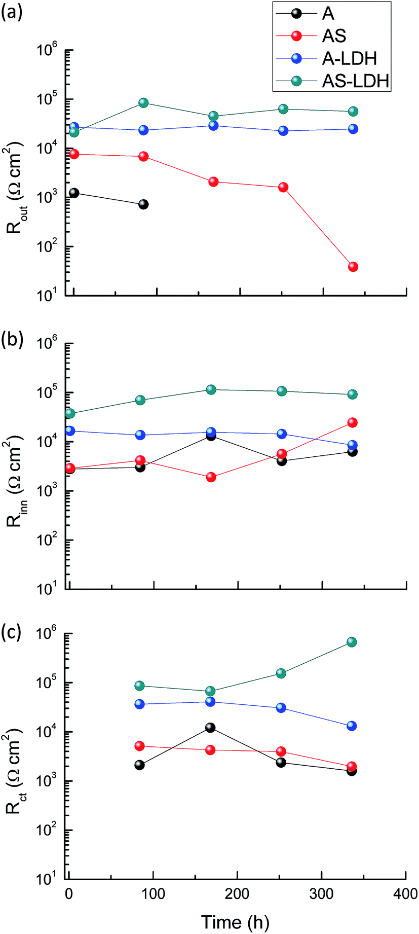 | ||
| Fig. 10 The evolution of (a) Rout, (b) Rinn and (c) Rct as a function of immersion time. | ||
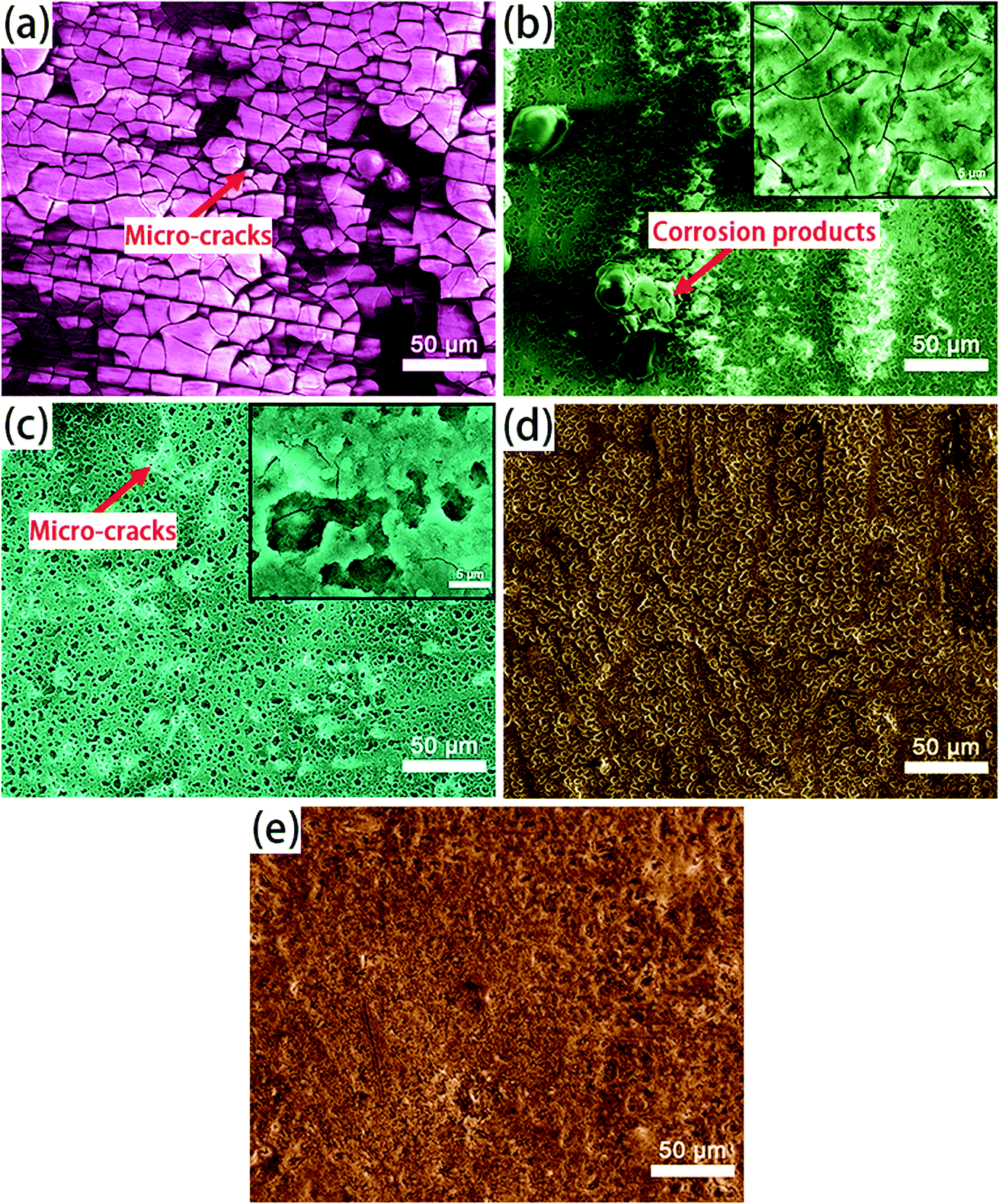 | ||
| Fig. 11 The surface microphotographs of (a) the substrate; (b) A; (c) AS; (d) A-LDH; (e) AS-LDH after 336 h immersion in 3.5 wt% NaCl solution. | ||
3.3 The effect mechanism of boiling water sealing
Based on the above analyses, the effect of boiling water sealing on the growth of LDHs are also discussed as follows. During the anodizing process, metallic Mg dissolves in the aqueous solutions releasing Mg2+ cations by an active dissolution reaction with high current density as eqn (1).45| Mg + H+ + H2O → Mg2+ + OH− + H2↑ | (1) |
Simultaneously, Mg2+ ions reaching the substrate/solution interface react with AlO2−, and as a result a mixed oxide of aluminium and magnesium was formed on the metallic substrate.46 Khaselev et al.47 showed that the content of MgAl2O4 was controlled by the aluminate concentration. It was also reported that elemental aluminium penetrated into the anodic film from the electrolyte as well as from Mg–Al alloy substrate.46–48 At the same time, the amorphous Mg(OH)2 was formed in the anodic film, as described by eqn (2). That is because eqn (1) leads to the accumulation of OH− ions at the liquid/metal interface and the sample are anodized in an alkaline environment.
| Mg2+ + OH− → Mg(OH)2↓ | (2) |
The above reaction likely results in the formation of a higher density of nuclei for Mg(OH)2 formation.
During the boiling water sealing process, the anodic layer at high temperatures would have a high kinetic energy and reactivity. As a result, the amorphous Mg(OH)2 gradual gather in blocks to form a layered nanostructure in the surface, as shown in Fig. 2d. The presence of a high nuclei density in a given area would hinder the growth of individual particles in 2 dimensions, leading to the formation of a film layer consisting of numerous Mg(OH)2 crystallites in the nano-size range. Moreover, the X-ray peaks (Fig. 1) of A and AS for Mg(OH)2 show low intensity and broad peaks, which confirmed that Mg(OH)2 in this film was present at a low degree of crystallization. The XPS result confirmed that the new Mg(OH)2 crystallites were generated at this time. This ultrafine and incomplete nature of such Mg(OH)2 deposition provides better protection to the underlying substrate (recall Fig. 11c).
Subsequently, the aluminum atoms that come from the dissolution of the anodic films diffuse into the Mg(OH)2 during the LDH-sealing process at the high temperature and pressure. The tetrahedral coordination of aluminum atoms converts into the octahedral one coordinated by hydroxyl groups, resulting in a positive charge on the layers. The carbonate ions, generated from the dissolution of CO2 from the air as eqn (3) and (4), are intercalated between the layers in order to maintain charge balance. This result attributes to carbonate ions an exceptionally high affinity to the LDHs. Accordingly, MgAl LDH synthesis could be explained via eqn (5).49
| H2O + CO2 → H+ + HCO3− | (3) |
| HCO3− → H+ + CO32− | (4) |
| Mg2+ + Al(OH)4− + OH− + H2O + CO32− → LDH-CO3 | (5) |
This new structure is characteristic of the LDHs. And, this Mg(OH)2-based substitution model without formation of polynuclear hydroxo complexes has been reported by Eliseev.50 The probable model is proposed, as sketched in Fig. 12. In addition, an other formation model also has been reported. They pointed out that the lamellar γ-AlOOH was formed in the initial stage of hydrolysis. They proposed a “gibbsite-based substitution-filling model” to present the structure of Mg–Al LDHs.51,52
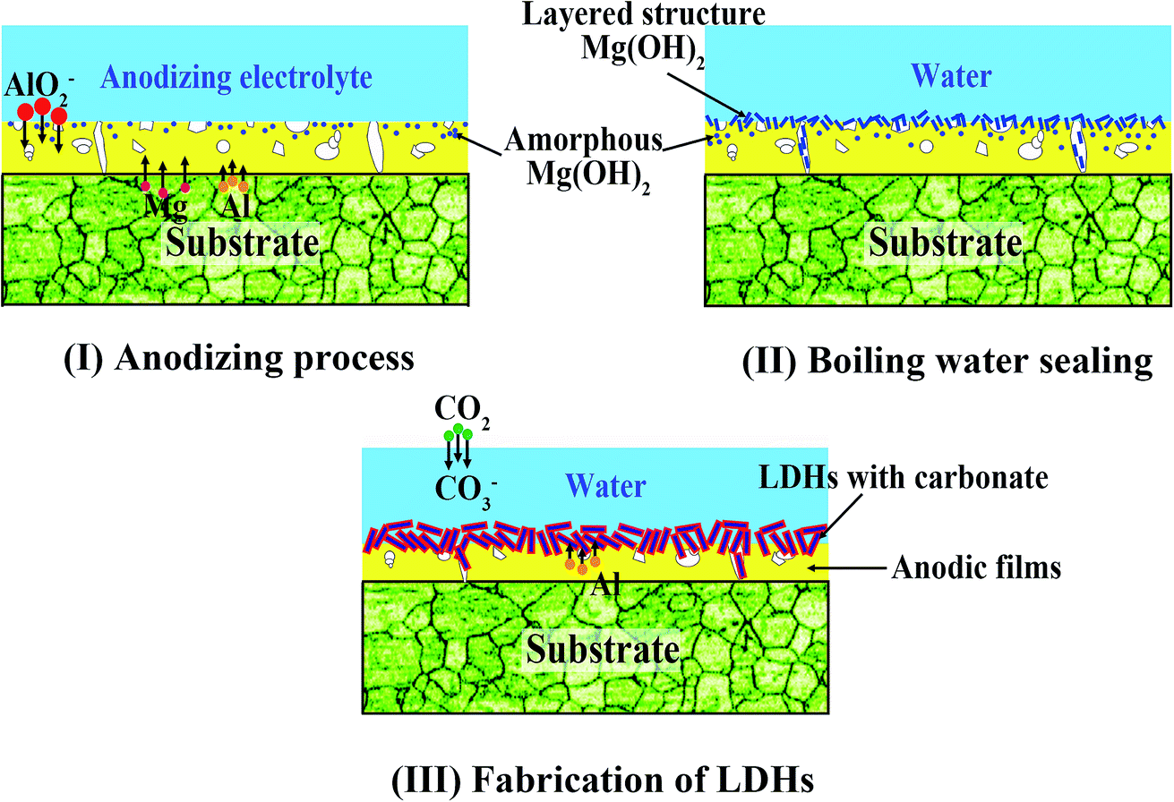 | ||
| Fig. 12 The mechanism model for the effect of boiling water sealing on the growth of LDHs. (I) The anodic film containing MgAl2O4 and amorphous Mg(OH)2 are generated from an active dissolution reaction with high current density. (II) The amorphous Mg(OH)2 gradually gathers in blocks to form a layered structure on the surface. (III) The aluminum atoms of the anodic films diffuse into Mg(OH)2 during the LDH-sealing process at the high temperature and pressure, which results in formation of LDHs on the anodic film. | ||
4. Conclusion
(1) MgAl-LDH with carbonate were successfully fabricated on anodized magnesium alloy of low Al content (AZ31) without introducing any kind of salts, just using anodic films composed of a mixed oxide of aluminium and magnesium as internal source of cations. And, the pH value of the solution was not needed to be adjusted in this method. Moreover, the pores of the anodic films were sealed after the in situ fabrication of the LDHs.(2) Boiling water sealing treatment led to the formation layered structure Mg(OH)2, which had a beneficial effect on subsequent growth of LDHs. The morphology of LDHs became fine and compact.
(3) LDHs which were fabricated on the anodized substrate with boiling water sealing treatment showed the best corrosion resistance in comparison with that of the others.
Conflicts of interest
There are no conflicts to declare.Acknowledgements
This work was supported by the National Key Research and Development Program of China (2016YFB0301100), the National Natural Science Foundation of China (51701029), Graduate Scientific Research and Innovation Foundation of Chongqing, China (CYS17002), China Postdoctoral Science Foundation Funded Project (2017M620410), the Chongqing Postdoctoral Scientific Research Foundation (Xm2017010), the Chongqing Research Program of Basic Research and Frontier Technology (cstc2016jcyjA0388, cstc2017jcyjBX0040).References
- A. Atrens, G.-L. Song, M. Liu, Z. Shi, F. Cao and M. S. Dargusch, Adv. Eng. Mater., 2015, 17, 400 CrossRef CAS.
- B. Feng, Y. C. Xin, F. L. Guo, H. H. Yu, Y. Wu and Q. Liu, Acta Mater., 2016, 120, 379 CrossRef CAS.
- F. S. Pan, X. H. Chen and T. Yan, A novel approach to melt purification of magnesium alloys, J. Magnesium Alloys, 2016, 4, 8 CrossRef CAS.
- M. C. Zhao, M. Liu, G. L. Song and A. Atrens, Adv. Eng. Mater., 2008, 10, 93 CrossRef CAS.
- S. S. Farhadi, M. Aliofkhazraei, G. Barati Darband, A. Abolhasani and A. Sabour Rouhaghdam, J. Magnesium Alloys, 2017, 5, 210 CrossRef CAS.
- Q. Dong, Z. Ba, Y. Jia, Y. Chen, X. Lv, X. Zhang and Z. Wang, J. Magnesium Alloys, 2017, 5, 320 CrossRef CAS.
- T. Ishizaki, N. Kamiyama, K. Watanabe and A. Serizawa, Corros. Sci., 2015, 92, 76 CrossRef CAS.
- R. G. Hu, S. Zhang, J. F. Bu, C. J. Lin and G. L. Song, Prog. Org. Coat., 2012, 73, 129 CrossRef CAS.
- C. Blawert, W. Dietzel, E. Ghali and G. Song, Adv. Eng. Mater., 2006, 8, 511 CrossRef CAS.
- J. J. Suay, E. Giménez and T. Rodríguez, Corros. Sci., 2003, 45, 611 CrossRef CAS.
- C. L. Chu, X. Han, F. Xue, J. Bai and P. K. Chu, Appl. Surf. Sci., 2013, 271, 271 CrossRef CAS.
- U. Malayoglu, K. C. Tekin and S. Shrestha, Surf. Coat. Technol., 2010, 205, 1793 CrossRef CAS.
- D. K. Ivanou, M. Starykevich, A. D. Lisenkov, M. L. Zheludkevich, H. B. Xue, S. V. Lamaka and M. G. S. Ferreira, Corros. Sci., 2013, 73, 300 CrossRef CAS.
- R. Arrabal, J. M. Mota, A. Criado, A. Pardo, M. Mohedano and E. Matykina, Surf. Coat. Technol., 2012, 206, 4692 CrossRef CAS.
- F. Zhang, Z. G. Liu, R. C. Zeng, S. Q. Li, H. Z. Cui, L. Song and E. H. Han, Surf. Coat. Technol., 2014, 258, 1152 CrossRef CAS.
- L. Wu, D. Yang, G. Zhang, Z. Zhang, S. Zhang, A. Tang and F. Pan, Appl. Surf. Sci., 2018, 431, 177 CrossRef CAS.
- J. Tedim, S. K. Poznyak, A. Kuznetsova, D. Raps, T. Hack, M. L. Zheludkevich and M. G. Ferreira, ACS Appl. Mater. Interfaces, 2010, 2, 1528 CAS.
- J. H. Syu, J. Y. Uan, M.-C. Lin and Z. Y. Lin, Corros. Sci., 2013, 68, 238 CrossRef CAS.
- K. H. Goh, T. T. Lim, A. Banas and Z. Dong, J. Hazard. Mater., 2010, 179, 818 CrossRef CAS PubMed.
- K. Li, N. Kumada, Y. Yonesaki, T. Takei, N. Kinomura, H. Wang and C. Wang, Mater. Chem. Phys., 2010, 121, 223 CrossRef CAS.
- T. Ishizaki, S. Chiba, K. Watanabe and H. Suzuki, J. Mater. Chem. A, 2013, 1, 8968 CAS.
- N. Kamiyama, G. Panomsuwan, E. Yamamoto, T. Sudare, N. Saito and T. Ishizaki, Surf. Coat. Technol., 2016, 286, 172 CrossRef CAS.
- L. Wu, G. Zhang, A. Tang, Y. Liu, A. Atrens and F. Pan, J. Electrochem. Soc., 2017, 164, C339 CrossRef CAS.
- J. Tedim, M. L. Zheludkevich, A. N. Salak, A. Lisenkov and M. G. S. Ferreira, J. Mater. Chem., 2011, 21, 15464 RSC.
- J. Tedim, M. L. Zheludkevich, A. C. Bastos, A. N. Salak, A. D. Lisenkov and M. G. S. Ferreira, Electrochim. Acta, 2014, 117, 164 CrossRef CAS.
- J. Tedim, A. C. Bastos, S. Kallip, M. L. Zheludkevich and M. G. S. Ferreira, Electrochim. Acta, 2016, 210, 215 CrossRef CAS.
- F. Wu, J. Liang, Z. Peng and B. Liu, Appl. Surf. Sci., 2014, 313, 834 CrossRef CAS.
- M. Zhou, L. Yan, H. Ling, Y. Diao, X. Pang, Y. Wang and K. Gao, Appl. Surf. Sci., 2017, 404, 246 CrossRef CAS.
- F. Chen, P. Yu and Y. Zhang, J. Alloys Compd., 2017, 15, 342 CrossRef.
- Y. Li, S. Li, Y. Zhang, M. Yu and J. Liu, J. Alloys Compd., 2015, 630, 29 CrossRef CAS.
- B. Kuznetsov, M. Serdechnova, J. Tedim, M. Starykevich, S. Kallip, M. P. Oliveira, T. Hack, S. Nixon, M. G. S. Ferreira and M. L. Zheludkevich, RSC Adv., 2016, 6, 13942 RSC.
- J. Chen, Y. Song, D. Shan and E. H. Han, Corros. Sci., 2011, 53, 3281 CrossRef CAS.
- Y. Zuo, P. H. Zhao and J. M. Zhao, Surf. Coat. Technol., 2003, 166, 237 CrossRef CAS.
- Z. Y. Yang, H. W. Zhou, J. C. Zhang and W. L. Cao, Acta Phys.-Chim. Sin., 2007, 23, 795 CrossRef CAS.
- S. Miyata, Clay Miner., 1983, 31, 305 CAS.
- G. Zhang, L. Wu, A. Tang, S. Zhang, B. Yuan, Z. Zheng and F. Pan, Adv. Mater. Interfaces, 2017, 4, 1700163 CrossRef.
- Y. Zhang, J. Liu, Y. Li, M. Yu, S. Li and B. Xue, J. Coat. Technol. Res., 2015, 12, 595 CrossRef CAS.
- H. Y. Hsiao, H. C. Tsung and W. T. Tsai, Surf. Coat. Technol., 2005, 199, 127 CrossRef CAS.
- B. R. Strohmeier, Surf. Sci. Spectra, 1994, 3, 121 CrossRef CAS.
- H. Y. Hsiao and W. T. Tsai, Surf. Coat. Technol., 2005, 190, 299 CrossRef CAS.
- D. E. Haycock, D. S. Urch, M. J. Webber and G. Wiech, J. Chem. Soc., Dalton Trans., 1997, 1978, 1785 Search PubMed.
- J. Chen, Y. Song, D. Shan and E. H. Han, Corros. Sci., 2012, 63, 148 CrossRef CAS.
- O. Sachiko, K. Hideo and M. Noboru, Mater. Trans., 2003, 44, 539 CrossRef.
- G. L. Song and Z. Shi, Corros. Sci., 2014, 85, 126 CrossRef CAS.
- S. J. Kim, M. Okido, Y. Mizutani and R. Ichino, Mater. Trans., 2003, 44, 1036 CrossRef CAS.
- O. Khaselev and J. Yahalom, J. Electrochem. Soc., 1998, 145, 190 CrossRef CAS.
- O. Khaselev, D. Weiss and J. Yahalom, Corros. Sci., 2001, 43, 1295 CrossRef CAS.
- S. Verdier, M. Boinet, S. Maximovitch and F. Dalard, Corros. Sci., 2005, 47, 1429 CrossRef CAS.
- Z. P. Xu and G. Q. Lu, Chem. Mater., 2005, 17, 1055 CrossRef CAS.
- A. A. Eliseev, A. V. Lukashin, A. A. Vertegel and V. P. Tarasov, Dokl. Chem., 2002, 387, 777 CrossRef.
- S. L. Ma, C. H. Fan, G. L. Huang, Y. M. Li, X. J. Yang and K. Ooi, Eur. J. Inorg. Chem., 2010, 2010, 2079 CrossRef.
- Y. Yang, X. Zhao, Y. Zhu and F. Zhang, Chem. Mater., 2012, 24, 81 CrossRef CAS.
Footnote |
| † Electronic supplementary information (ESI) available. See DOI: 10.1039/c7ra11683g |
| This journal is © The Royal Society of Chemistry 2018 |