 Open Access Article
A thin TiO2 NTs/GO hybrid membrane applied as an interlayer for lithium–sulfur batteries†
Haimei Song‡
b,
Chen Zuo‡a,
Xiaoqian Xua,
Yuanxin Wanc,
Lijie Wangb,
Dongshan Zhou *a and
Zhijun Chen*b
aDepartment of Polymer Science and Engineering, School of Chemistry and Chemical Engineering, State Key Laboratory of Coordination Chemistry, Nanjing National Laboratory of Microstructure, Nanjing University, Nanjing, 210093, P. R. China. E-mail: dzhou@nju.edu.cn
bSchool of Material and Chemical Engineering, Henan Provincial Key Laboratory of Surface and Interface Science, Zhengzhou University of Light Industry, Zhengzhou 450002, P. R. China. E-mail: chenzj@zzuli.edu.cn
cSchool of Advanced Materials, Peking University Shenzhen Graduate School, Shenzhen 518055, China
First published on 2nd January 2018
Abstract
Lithium–sulfur batteries hold great promise for serving as next generation high energy density batteries. However, the shuttle of polysulfide induces rapid poor cycling stability of lithium–sulfur cells. Using an interlayer inserted between the sulfur cathode and the separator to capture these soluble intermediates can diminish this effect effectively. Herein, a ultrathin TiO2 nanotubes/graphene oxide (TiO2 NTs/GO) hybrid membrane (the thickness is less than 10 μm) used as an interlayer in lithium sulfur battery can effectively improve the cycle performance by trapping the soluble polysulfides. As a result, the sulfur cathode with TiO2 NTs/GO hybrid membrane as interlayer exhibits an initial discharge capacity of 1431.5 mA h g−1 and maintains the reversible capacity of 845.8 mA h g−1 at 0.1C after 100 cycles.
1. Introduction
Li–S batteries have been considered as one of the most promising candidates for next generation energy storage systems for their high theoretical capacity (1675 mA h g−1) and high theoretical specific energy (2600 W h kg−1), which is about 10 times that of commercial lithium-ion batteries. Besides, sulfur is naturally abundant, low cost and environmentally friendly, which potentially makes Li–S batteries more suitable for commercialization.1,2 However, the practical applications of Li–S batteries are significantly hampered by the low electronic/ionic conductivity of sulfur and the discharge products, large volume charge of sulfur during the lithiation/delithiation process, and the shuttling of dissolved lithium polysulfides (Li2Sx, 4 ≤ x ≤ 8) in organic liquid electrolytes. These problems eventually lead to high polarization, serious capacity fading and poor rate stability.3–5Many approaches have been explored to solve these issues and improve the electrochemical performance of Li–S batteries. And most studies are focusing on embedding sulfur in/on different conductive porous frameworks such as carbon materials,6–8 conducting polymers9–12 and metal oxides.13–25 For example, Wang reported a mesoporous nitrogen-doped carbon (MPNC)–sulfur nanocomposite as a novel cathode for advanced Li–S batteries. The MPNC–sulfur cathodes show excellent cycling stability (95% retention within 100 cycles).26,27 On the one hand, the introduction of conductive porous frameworks improves the electronic conductivity of sulfur cathode and provides enough space for volume expansion; on the other hand, it also suppresses the diffusion of polysulfide. Nevertheless, the fabrication procedures are always complicated and the active materials loading in the cathode gets decreased. Therefore, more effective approaches are necessary to be set up for the commercialization of Li–S battery.
Besides all of the efforts mentioned above, it has been found that using a functional membrane as an interlayer inserted between the sulfur cathode and the separator would be a crucial factor in improving the cyclic stability of Li–S batteries.28–35 During the cell discharge, the dissolved polysulfide will move towards the anode, driven by the chemical potential and the concentration differences. The interlayer with many functional groups could localize the polysulfide species at the cathode side and is considered to be a polysulfide trap. Manthiram research group firstly proposed this important concept of “interlayer” in 2012. Peng et al.36 adopted electrospinning technology to directly coat the interlayer on the sulfur cathode. And an initial discharge capacity of 1279 mA h g−1 was achieved. But the thickness of the PAN (polyacrylonitrile)–NC (nitrogen-doped carbon black) layer is about 50 μm. Usually, the thickness of standalone interlayer is about tens to hundreds of micron to support its construction and cell assembly.37–43 But the increased thickness would have adverse effect on Li+ transport and decrease the total energy density.
Here, we designed a thin TiO2 NTs/GO hybrid membrane used as an interlayer in Li–S batteries between the sulfur cathode and the separator. The TiO2 NTs/GO hybrid membrane was fabricated by a simple filtration method. Coupling TiO2 additives to C–S composite is able to improve the cycle life and the capacity retention, which was contributed to an electrostatic attraction (S–Ti–O) that improved the surface adsorption of polysulfides on the TiO2.44–46 Besides, the graphene with its unique 3D interconnected network structure was able to store the shuttling polysulfide intermediates during cycling.47,48 What's more, the thickness of the TiO2 NTs/GO hybrid membrane is less than 10 μm, which is far thinner than any other reported membranes used as interlayer in lithium–sulfur batteries. As a result, it showed that the discharge capacity and the cycling stability of Li–S batteries were significantly improved when using a TiO2 NTs/GO hybrid membrane as interlayer.
2. Experimental
2.1 Preparation of TiO2 nanotubes
TiO2 NTs were synthesized by a typical method.49 Anatase titanium dioxide nanopowders (Aldrich, 99.7%, <25 nm) were dispersed in sodium hydroxide solution (15 mL, 10 M). The mixed solution was stirred to a uniform dispersion by magnetic stirring and transferred to a Teflon stainless steel autoclave, under magnetic stirring, 130 °C of hydrothermal reaction for 24 hours. When cooled at room temperature, the precipitate was washed to pH approximately equal to 9 and washed with nitric acid (0.1 M) 3 times (hydrogen ion exchange process). Finally, the product was rinsed with deionized water until pH was neutral. The product was centrifuged at 4000 rpm for 5 minutes. After drying, the product was heated in a tube furnace at 5 °C min−1. The temperature was raised to 400 °C and kept for 6 hours. The final product was TiO2 NTs.2.2 Preparation of TiO2 NTs/GO hybrid membranes
To obtain the TiO2 NTs/GO hybrid membrane, TiO2 NTs were dispersed in the dispersions of graphene oxide (XFNANO, INC, 2 mg mL−1 <500 nm) by high-power ultra-sonication for several hours. After adding hydriodic acid and reacting for several hours, the mixture was vacuum filtered through a nylon membrane. The hybrid membrane could be easily peeled from the filter surface after washing with de-ionized water and dried at 60 °C. The films of different thicknesses were prepared by modulating the volume of GO dispersions. The GO membrane was prepared exactly the same as the TiO2 NTs/GO hybrid membranes except for the addition of TiO2 NTs.2.3 Preparation of the CMK-3/S composite
The CMK-3/S composite (70% S content, Fig. S1†) was obtained by a melt-infusion method of heating the mixture of CMK-3 and S at 155 °C for 12 h.2.4 Preparation of the L2S7 solution
Sulfur and Li2S were added to the appropriate amount of DOL/DME (1![[thin space (1/6-em)]](https://www.rsc.org/images/entities/char_2009.gif) :
:![[thin space (1/6-em)]](https://www.rsc.org/images/entities/char_2009.gif) 1, v/v) solvent at a molar ratio of 6
1, v/v) solvent at a molar ratio of 6![[thin space (1/6-em)]](https://www.rsc.org/images/entities/char_2009.gif) :
:![[thin space (1/6-em)]](https://www.rsc.org/images/entities/char_2009.gif) 1.50 The mixed solution was placed under magnetic stirring at 60 °C for over 24 hours until the sulfur was completely dissolved in the glove box filled with argon gas.
1.50 The mixed solution was placed under magnetic stirring at 60 °C for over 24 hours until the sulfur was completely dissolved in the glove box filled with argon gas.
2.5 Material characterization
Field emission scanning electron microscopy (SEM, Nova Nano SEM 230) and transmission electron microscopy (TEM, Tecnai G2 20ST) were employed to characterize the morphology. The elements on the surface of sample were identified by energy dispersive X-ray spectroscopy (EDS). X-ray diffraction patterns (XRD) were obtained with a D/MAX-2400 diffractometer using Cu Kα radiation (40 kV, 100 mA, λ = 1.54056 Å).2.6 Electrochemical measurements
The working electrode material consists of 80 wt% sulfur–carbon, 10 wt% super P and 10 wt% poly(vinylidene-fluoride) (PVDF), which was coated on aluminium foil. The mass loading of the active material sulfur was about 0.6 mg cm−2. The specific capacity of the cell was based on the mass of sulfur in this paper. All the cells with different membranes in this work were fabricated with this kind of cathode.The positive electrode was used as the research electrode, and the lithium wafer was the opposite electrode. The polypropylene porous film (Celgard 2400) was used as the diaphragm. 1.0 M lithium bis(trifluoromethanesulfonyl)imide (LiTFSI)/DOL (1,3 dioxolane) + DME (dimethoxyethane) [1% wt% LiNO3] as electrolyte in the glove box filled with argon in the assembled CR2032 button battery. And the TiO2 NTs/GO hybrid membrane and the GO membrane were inserted between the sulfur cathode and the separator when assembled into the cell.
Galvanostatic charge–discharge tests were performed in the potential range of 1.5–3.0 V at 256C by using a LAND CT2001A battery-testing instrument. EIS measurements were conducted by using a PARSTAT 2273 electrochemical measurement system. EIS measurements were carried out at the open-circuit potential in the frequency range between 100 kHz and 100 mHz with perturbation amplitude of 5 mV.
3. Results and discussion
3.1 Material characterization
TiO2 NTs/GO hybrid membrane was prepared by a simple vacuum filtration method with the mixture of TiO2 NTs and GO, as showed in Fig. 1. The hybrid membrane could be easily peeled from the filter surface and used as a freestanding interlayer. When assembled into the cell, the TiO2 NTs/GO hybrid membrane was sandwiched between the sulfur cathode and the separator. It should be emphasized that flexibility is critical for membranes as interlayers. And the as-obtained hybrid membrane shows excellent flexibility, as illustrated in the inset of Fig. 1. Usually, the flexibility of the membrane will facilitate the cell assembling and particularly prevent the interlayer pulverization during cycling. So it indicates the potential applications of TiO2 NTs/GO hybrid membrane as electrodes for flexible energy storage devices.The SEM image of the surface of GO membrane is displayed in Fig. 2a. It can be seen that the graphene oxide film exhibits a rough surface composed of graphene oxide layers. Fig. 2b shows the transmission electron microscope (TEM) image of TiO2 NTs that are intertwined with each other, forming a 3D network structures. TiO2 NTs can support the surface area of GO and increase the barrier free absorption of lithium polysulfide.
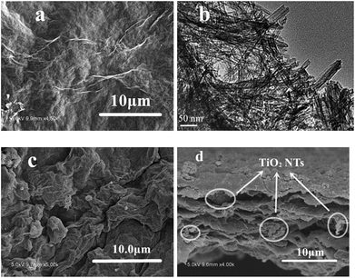 | ||
| Fig. 2 (a) SEM image of the surface of GO membrane, (b) TEM image of TiO2 NTs, (c) SEM image of the surface of TiO2 NTs/GO hybrid membrane, (d) cross section SEM image of TiO2 NTs/GO hybrid membrane. | ||
Fig. 2c shows typical front-view SEM images of the TiO2 NTs/GO hybrid membrane, which exhibit the homogeneous distribution of TiO2 NTs on the interconnected and overlapped graphene sheets. The cross-view SEM image of the hybrid membrane is shown in Fig. 2d. It shows the thickness of the membrane is less than 10 μm. The graphene oxide layers stacked together with TiO2 NTs encapsulated in it. In order to confirm that TiO2 NTs were composed with the graphene oxide, element mapping by energy dispersive X-ray spectroscopy (EDS) was conducted (Fig. S2†). It can be seen that TiO2 NTs were homogeneously distributed in the layered structure that was constructed by graphene oxide.
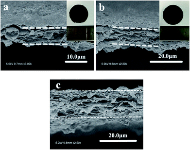
In order to find the most suitable thickness of hybrid membrane, here we prepared a series of membrane with different thickness and the electrochemical performance of cells with these membranes as interlayers were compared in Fig. S3.† Once the hybrid membrane is too thin, it is hard to be peeled from the filter surface and is too brittle to be assembled into the cell. So as shown in Fig. 3a, the least thickness is about 8 μm to form an integrated hybrid membrane. And it can be seen from the Fig. S3,† all of the cells with different membrane almost exhibit preferable cycling performance. As mentioned above, the thickness of the hybrid membrane used as interlayer can affect the performance of the cell. Once the film is too thick, the increased thickness would have adverse effect on Li+ transport and decrease the total volumetric energy density. Considering the total mass of the cell and the Li+ transport ability, the most suitable thickness of the hybrid membrane is about 8 μm, which is still able to maintain great cycle stability. And it is far thinner than any other reported membranes used as interlayer in lithium–sulfur batteries.
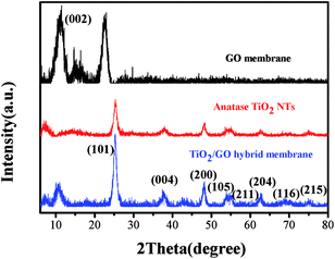
Fig. 4 shows the X-ray diffraction (XRD) spectra of GO membrane, TiO2 NTs and TiO2 NTs/GO hybrid membrane. The sharp peaks present at 10.8 degrees are characteristic peaks of GO. All the peaks of TiO2 nanotubes have been identified and can be assigned to the anatase phase (JCPDS Card no. 21-1272). Compared with the GO film, a characteristic peak of TiO2 NTs/GO hybrid membrane disappeared at about 23 degrees, because the graphene oxide was partially reduced by ultrasonic HI acid. The characteristic diffraction peaks of TiO2 NTs/GO hybrid membrane and TiO2 NTs coincide basically. These results indicate that TiO2 NTs are loaded into the composite films, in which TiO2 NTs are in the form of crystalline structure.
3.2 Electrochemical properties
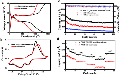
The charge–discharge profiles of TiO2 NTs/GO hybrid membrane and GO membrane electrode at 0.1C in the 1st cycle are shown in Fig. 5a. Both of the two electrodes exhibit a typical two-plateau discharge curve, indicating that the two cathodes exhibit the same electrochemical behavior as conventional Li–S batteries. The two discharge plateaus at 2.3 V and 2.0 V are corresponding to the generation of long-chain polysulfides (Li2Sx, 4 ≤ x ≤ 8) and Li2S2/Li2S respectively.Fig. 5b shows the cyclic voltammetry (CV) curve of a cell assembled by a titanium dioxide film at the scan rate of 0.1 mV s−1, with a scanning range of 1.5 to 3 V. As can be seen from the diagram, the reaction of sulfur and lithium in the active material is a multi-step reaction process. The negative scan showed two reduction peaks at 2.3 V and 1.9 V, respectively. The reduction peak at 2.3 V corresponds to the process of conversion of sulfur to long chain lithium polysulfide (Li2Sx, x = 4–8). The reduction peak at 1.9 V corresponds to the process of further conversion of long chain lithium sulfide to short chain lithium polysulfide (Li2Sx, x = 2–4) and lithium sulfide (Li2S). The sharp oxidation peaks in the forward scan of 2.45 V correspond to the process of oxidation of lithium polysulfide and Li2S to sulfur. The two step reduction peaks in the cathode scan and the two overlapping oxidation peaks in the anode scan are consistent with the current peaks in charge/discharge curves. The CV curve keeps good coincidence, indicating that the battery with the TiO2 NTs/GO hybrid membrane has good reversible capacity and cycle stability.
Cycling tests were performed at 0.1C to investigate the cycling stability of the electrodes with different membranes. As shown in Fig. 5c, the electrode with TiO2 NTs/GO hybrid membrane exhibited the best cycling performance. After 100 cycles, a discharge capacity of 850.7 mA h g−1 still remained, which corresponds to capacity decay retention of only 0.409% per cycle. This excellent cycling stability may be attributed to the synergistic effects of both the interconnected graphene conductive network and the excellent adsorption capacity of TiO2 nanotubes to polysulfides.
The rate capabilities of TiO2 NTs/GO hybrid membrane and GO membrane were compared in Fig. 5d. As seen in Fig. 5d, the TiO2 NTs/GO hybrid membrane delivers much higher specific capacity than GO membrane at all rate conditions. The battery capacity decrease with the increase of current rate is due to the internal resistance induced polarization. The higher specific capacity and better rate capability of TiO2 NTs/GO hybrid membrane should be associated with its unique structure that TiO2 nanotubes encapsulated in the 3D graphene network enables a faster ion transport in the compact graphene and a more efficient utilization of sulfur of sulfur compared with GO membrane.
The role of different interlayers in Li–S batteries was further probed by electrochemical impedance spectroscopy (EIS). Nyquist plots of the cell impedance are shown in Fig. S4.† Both cells exhibit typical semicircles at medium-frequency region and inclined lines in the low-frequency region. The cells with TiO2 NTs/GO hybrid membrane show smaller semicircle diameter at medium frequency, and higher slope at low frequency than cells with GO membrane, which means a faster charge transfer.32 The additional electron pathways to active material can improve the redox chemistry of S and enhancing the active material utilization. Simultaneously, the interlayer could effectively reuse the dissolved active materials and mitigate surface aggregation, thus providing better performance.33
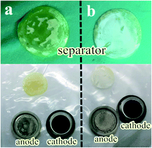
The optical images of electrodes, separators and Li anodes are also described. As shown in Fig. 6, the morphology of the removed cells after cycling is compared. The electrode still maintained the original shape without interlayer, but the separator was covered with yellow soluble sulfur and lithium anode become black gray, participating in the destruction of the surface after 100 cycles from Fig. 6a. It is worth noting that when the interlayer is added, the surface corrosion of the lithium anode is to a certain extent as shown in Fig. 6b. Based on these facts, we can conclude that the lithium sulfur battery can effectively inhibit the “spindle effect” or polysulfide dissolution after adding interlayer.
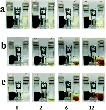
The polysulfide permeability of different membrane samples was tested as showed in Fig. 7. Type H glass is used to hold DOL/DME solvents and, in contrast, 0.5 M Li2S7 solution in the left ventricle, where the two chamber is separated by conventional membranes or hybrid membranes. Under the pressure/concentration gradient, the polysulfide all diffused gradually through the membrane. As showed in Fig. 7c, the color changed fast in the right vial and turned to dark brown after 12 h, indicating a fast polysulfide diffusion of Celgard 2400 separator. The GO membrane shows a good polysulfide separating ability as the polysulfide permeation rate was much slower. Interestingly, the TiO2 NTs/GO composite membrane exhibited a better performance. After 12 h, the color only changed a little. This phenomenon indicates that the TiO2 NTs/GO hybrid membrane can help immobilize the polysulfide.
4. Conclusions
In summary, a functional membrane composed of TiO2 nanotubes and graphene oxide is simply fabricated and applied as interlayer in the lithium–sulfur batteries, which substantially improve the electrochemical performance of Li–S battery. The unique structure of TiO2 NTs/GO hybrid membrane suppresses the shuttle effect owing to the adsorption effect of TiO2 nanotubes to polysulfides and facilitates electron transport for high active-material utilization. Besides, the thickness of the TiO2 NTs/GO hybrid membrane is less than 10 μm, which is far thinner than any other reported membranes used as interlayer in lithium–sulfur batteries. The strategy proposed in this study indicates the possibility of even higher total energy density compared with cells using other different interlayers.Conflicts of interest
There are no conflicts to declare.Acknowledgements
This work was financially supported by the National Natural Science Foundation of China (No. 21474049, 51673034, 21574063, 21404055, 21272260, 21271160), the Shenzhen Science and Technology Innovation Committee (JCYJ20160531151102203, JCYJ20160608140827794). Haimei Song gratefully appreciates the support from the Scientific Research Foundation of Graduate School of Nanjing University and Zhengzhou University of Light Industry.Notes and references
- Y. X. Yin, S. Xin, Y. G. Guo and L. J. Wan, Angew. Chem., 2013, 52, 13186–13200 CrossRef CAS PubMed.
- A. Manthiram, Y. Fu, S. H. Chung, C. Zu and Y. S. Su, Chem. Rev., 2014, 114, 11751–11787 CrossRef CAS PubMed.
- A. Manthiram, S. H. Chung and C. Zu, Adv. Mater., 2015, 27, 1980–2006 CrossRef CAS PubMed.
- Z. W. Seh, Y. Sun, Q. Zhang and Y. Cui, Chem. Soc. Rev., 2016, 45, 5605–5634 RSC.
- Y. Wan, Y. Sha, S. Luo, W. Deng, X. Wang, G. Xue and D. Zhou, J. Power Sources, 2015, 295, 41–46 CrossRef CAS.
- L. Sun, D. Wang, Y. Luo, K. Wang, W. Kong, Y. Wu, L. Zhang, K. Jiang, Q. Li, Y. Zhang, J. Wang and S. Fan, ACS Nano, 2016, 10, 1300–1308 CrossRef CAS PubMed.
- D. Su, M. Cortie and G. Wang, Adv. Energy Mater., 2017, 7, 1602014 CrossRef.
- G. Hu, Z. Sun, C. Shi, R. Fang, J. Chen, P. Hou, C. Liu, H. M. Cheng and F. Li, Adv. Mater., 2017, 29, 5222–5234 Search PubMed.
- J. Song, H. Noh, J. Lee, I.-W. Nah, W.-I. Cho and H.-T. Kim, J. Power Sources, 2016, 332, 72–78 CrossRef CAS.
- W. Zhou, Y. Yu, H. Chen, F. J. DiSalvo and H. D. Abruna, J. Am. Chem. Soc., 2013, 135, 16736–16743 CrossRef CAS PubMed.
- W. Li, Q. Zhang, G. Zheng, Z. W. Seh, H. Yao and Y. Cui, Nano Lett., 2013, 13, 5534–5540 CrossRef CAS PubMed.
- Z. Z. Li and Y. Pan, J. Polym. Mater., 2015, 32, 237–245 CrossRef CAS.
- Q. Pang, X. Liang, C. Y. Kwok and L. F. Nazar, J. Electrochem. Soc., 2015, 162, A2567–A2576 CrossRef CAS.
- X. Gu, S. Zhang and Y. Hou, Chin. J. Chem., 2016, 34, 13–31 CrossRef CAS.
- Z. Li, H. B. Wu and X. W. Lou, Energy Environ. Sci., 2016, 9, 3061–3070 CAS.
- X. Liang, C. Y. Kwok, F. Lodi-Marzano, Q. Pang, M. Cuisinier, H. Huang, C. J. Hart, D. Houtarde, K. Kaup, H. Sommer, T. Brezesinski, J. Janek and L. F. Nazar, Adv. Energy Mater., 2016, 6, 1501636 CrossRef.
- M. Liu, X. Qin, Y.-B. He, B. Li and F. Kang, J. Mater. Chem. A, 2017, 5, 5222–5234 CAS.
- X. Liu, J. Q. Huang, Q. Zhang and L. Mai, Adv. Mater., 2017, 29, 1601759 CrossRef PubMed.
- O. Ogoke, G. Wu, X. Wang, A. Casimir, L. Ma, T. Wu and J. Lu, J. Mater. Chem. A, 2017, 5, 448–469 CAS.
- S. Rehman, K. Khan, Y. Zhao and Y. Hou, J. Mater. Chem. A, 2017, 5, 3014–3038 CAS.
- X. Tao, J. Wang, Z. Ying, Q. Cai, G. Zheng, Y. Gan, H. Huang, Y. Xia, C. Liang, W. Zhang and Y. Cui, Nano Lett., 2014, 14, 5288–5294 CrossRef CAS PubMed.
- J. X. Zhang, Z. S. Ma, J. J. Cheng, Y. Wang, C. Wu, Y. Pan and C. Lu, J. Electroanal. Chem., 2015, 738, 184–187 CrossRef CAS.
- X. Gao, Y. Wang, Z. Ma, W. Jiang, Y. Zou and C. Lu, J. Mater. Sci., 2016, 51, 5139–5145 CrossRef CAS.
- Z.-Z. Yang, H.-Y. Wang, L. Lu, C. Wang, X.-B. Zhong, J.-G. Wang and Q.-C. Jiang, Sci. Rep., 2016, 6, 22990 CrossRef CAS PubMed.
- J. Cheng, Y. Pan, J. Zhu, Z. Li, J. Pan and Z. Ma, J. Power Sources, 2014, 257, 192–197 CrossRef CAS.
- J. Song, T. Xu, M. L. Gordin, P. Zhu, D. Lv, Y.-B. Jiang, Y. Chen, Y. Duan and D. Wang, Adv. Funct. Mater., 2014, 24, 1243–1250 CrossRef CAS.
- Y. Wan, X. Xu, J. Liu, Y. Sha, Y. Chen, L. Li, G. Xue, X. Wang and D. Zhou, Adv. Mater. Technol., 2017, 2, 1600156 CrossRef.
- G. Ma, Z. Wen, J. Jin, M. Wu, X. Wu and J. Zhang, J. Power Sources, 2014, 267, 542–546 CrossRef CAS.
- J. Wang, Y. Yang and F. Kang, Electrochim. Acta, 2015, 168, 271–276 CrossRef CAS.
- Z. Xiao, Z. Yang, L. Wang, H. Nie, M. Zhong, Q. Lai, X. Xu, L. Zhang and S. Huang, Adv. Mater., 2015, 27, 2891–2898 CrossRef CAS PubMed.
- Q. Zeng, X. Leng, K.-H. Wu, I. R. Gentle and D.-W. Wang, Carbon, 2015, 93, 611–619 CrossRef CAS.
- Z. Zhang, G. Wang, Y. Lai and J. Li, J. Alloys Compd., 2016, 663, 501–506 CrossRef CAS.
- S. Li, G. Ren, M. N. F. Hoque, Z. Dong, J. Warzywoda and Z. Fan, Appl. Surf. Sci., 2017, 396, 637–643 CrossRef CAS.
- J.-Q. Huang, Q. Zhang and F. Wei, Energy Storage Materials, 2015, 1, 127–145 CrossRef.
- J. Y. Hwang, H. M. Kim, S. K. Lee, J. H. Lee, A. Abouimrane, M. A. Khaleel, I. Belharouak, A. Manthiram and Y. K. Sun, Adv. Energy Mater., 2015, 6, 448–469 Search PubMed.
- Y. Peng, Y. Zhang, Y. Wang, X. Shen, F. Wang, H. Li, B. J. Hwang and J. Zhao, ACS Appl. Mater. Interfaces, 2017, 9, 29804–29811 CAS.
- J. Wang, Y. Yang and F. Kang, Electrochim. Acta, 2015, 168, 271–276 CrossRef CAS.
- J.-Q. Huang, B. Zhang, Z.-L. Xu, S. Abouali, M. Akbari Garakani, J. Huang and J.-K. Kim, J. Power Sources, 2015, 285, 43–50 CrossRef CAS.
- C.-L. Lee and I.-D. Kim, Nanoscale, 2015, 7, 10362–10367 RSC.
- Z. Wang, X. Wang, W. Sun and K. Sun, Electrochim. Acta, 2017, 252, 127–137 CrossRef CAS.
- J. Zhang, H. Li, Z. Lin, Q. Tang, W. Qi, L. Wang, H. Zheng and K. Zhou, RSC Adv., 2017, 7, 39172–39177 RSC.
- Y.-D. Shen, Z.-C. Xiao, L.-X. Miao, D.-B. Kong, X.-Y. Zheng, Y.-H. Chang and L.-J. Zhi, Rare Met., 2017, 36, 418–424 CrossRef CAS.
- Y. Fan, Z. Yang, W. Hua, D. Liu, T. Tao, M. M. Rahman, W. Lei, S. Huang and Y. Chen, Adv. Energy Mater., 2017, 7, 1602380 CrossRef.
- J. Li, B. Ding, G. Xu, L. Hou, X. Zhang and C. Yuan, Nanoscale, 2013, 5, 5743–5746 RSC.
- Z. Wei Seh, W. Li, J. J. Cha, G. Zheng, Y. Yang, M. T. McDowell, P. C. Hsu and Y. Cui, Nat. Commun., 2013, 4, 1331 CrossRef PubMed.
- Z. Zhang, Q. Li, S. Jiang, K. Zhang, Y. Lai and J. Li, Chemistry, 2015, 21, 1343–1349 CrossRef CAS PubMed.
- F. Nitze, M. Agostini, F. Lundin, A. E. Palmqvist and A. Matic, Sci. Rep., 2016, 6, 39615 CrossRef CAS PubMed.
- J.-Q. Huang, X.-F. Liu, Q. Zhang, C.-M. Chen, M.-Q. Zhao, S.-M. Zhang, W. Zhu, W.-Z. Qian and F. Wei, Nano Energy, 2013, 2, 314–321 CrossRef CAS.
- Y. Tang, Y. Zhang, J. Deng, J. Wei, H. L. Tam, B. K. Chandran, Z. Dong, Z. Chen and X. Chen, Adv. Mater., 2014, 26, 6111–6118 CrossRef CAS PubMed.
- J.-Q. Huang, T.-Z. Zhuang, Q. Zhang, H.-J. Peng, C.-M. Chen and F. Wei, ACS Nano, 2015, 9, 3002–3011 CrossRef CAS PubMed.
Footnotes |
| † Electronic supplementary information (ESI) available. See DOI: 10.1039/c7ra10858c |
| ‡ These authors contributed equally to this work. |
| This journal is © The Royal Society of Chemistry 2018 |


