
 Open Access Article
 This Open Access Article is licensed under a Creative Commons Attribution-Non Commercial 3.0 Unported Licence
Controlled chemical synthesis of CaO2 particles coated with polyethylene glycol: characterization of crystallite size and oxygen release kinetics
Arghavan Rastinfard a,
Masoumeh Haghbin Nazarpak*b and
Fathollah Moztarzadeha
a,
Masoumeh Haghbin Nazarpak*b and
Fathollah Moztarzadeha
aDepartment of Biomedical Engineering, Amirkabir University of Technology, P.O. Box: 15875-4413, Tehran 159163-4311, Iran
bNew Technologies Research Center (NTRC), Amirkabir University of Technology, Tehran 15875-4413, Iran. E-mail: mhaghbinn@gmail.com
First published on 19th December 2017
Abstract
Incorporating oxygen generating substances into tissue constructs is one of the methods for increasing cell survival under hypoxic condition. Calcium peroxide from alkaline earth metal peroxide groups has been proposed as an appropriate compound for supplying sufficient oxygen to cells within the scaffolds. The high surface-to-volume ratio of CaO2 particles can lead to an increase in oxygen generation ability over a particular time interval. One objective of this study was to decrease calcium peroxide crystallite size via changing the local supersaturation level by controlling the reactant addition rate during coprecipitation synthesis. Therefore, the effect of hydrogen peroxide addition rate on the crystallite size, particle size distribution, and CaO2 purity, which have not been studied before, were discussed. It was found that the crystallite size of CaO2 depends upon the reactant addition rate, and the crystallite size decreased from 111 to 37 nm when the addition rate increased from 0.29 to 0.88 ml min−1. Furthermore, after determining the hydrogen peroxide addition rate, a facile method was developed to prepare CaO2 particles with polyethylene glycol coating for the first time. The aim of PEG coating was to improve redispersion of the precipitated CaO2 particles. Thermogravimetric analysis was used to measure the content of adsorbed PEG on the surface of the particles. Eventually, the oxygen release profile of PEG-coated calcium peroxide particles demonstrated that the release kinetics is dependent on the pH value of the exterior medium, diffusion through the calcium carbonate product layer, and molar ratios of PEG to calcium.
1. Introduction
Though substantial progress has been achieved in improving the physical environment required for cell growth, engineering an ideal structural scaffold is a persistent challenge.1 It is typically owing to the insufficient or inevitably delayed vascularization of the scaffold.2 That, in turn, hampers oxygen and nutrient delivery and removal of waste products3 because oxygen deficiency arises when cells are beyond 100–200 microns away from blood vessels.4 Moreover, tissue trauma can bring about tissue hypoxia and prevent oxygen diffusion due to the destruction of the vascularization network.1 Eventually, hypoxic condition established as a result of reasons mentioned above can induce cellular necrosis and apoptosis.5The oxygen generating biomaterials, by administering sufficient oxygen for cells, eliminate the onset of hypoxia within tissue constructs from the time of implantation to vascularization,6 leading to an increase in cell survival before the vascularization.7 Recently, different types of peroxide compounds such as liquid hydrogen peroxide and inorganic peroxides, e.g., calcium peroxide (CaO2), magnesium peroxide (MgO2), and sodium percarbonate (Na2CO3·1.5H2O2), have been proposed as oxygen generating biomaterials.5 Oxygen release from the solid peroxides, contrary to liquid hydrogen peroxide directly decomposing to molecular oxygen, is a two-step process.8 Therefore, solid inorganic peroxides can induce more sustained oxygen release compared to liquid hydrogen peroxide.5 Inorganic peroxides form hydrogen peroxide as a result of hydrolysis when exposed to water and then liberate oxygen gas by decomposition of hydrogen peroxide.9 For example, calcium peroxide releases oxygen via the following reactions:10
| CaO2 (s) + 2H2O → Ca(OH)2 + H2O2 | (1) |
| 2H2O2 → O2 + 2H2O | (2) |
However, in alkaline condition (pH = 12–13), CaO2 is directly converted to molecular oxygen instead of H2O2 and no measurable H2O2 is released because of increasing the disproportionation of H2O2 to O2 [eqn (2)] by increasing the pH value.11 Calcium peroxide has been preferred over other inorganic peroxides since the oxygen release from CaO2 is slower than that from sodium percarbonate.10,12 Moreover, CaO2 enables higher oxygen production capacity compared to MgO2 due to the higher purity of commercial CaO2.12
Calcium peroxide, contrary to other alkaline earth metal peroxides such as SrO2 and BaO2, cannot be synthesized through direct reaction of molecular oxygen with calcium oxide.13 Thus, two other methods have been proposed for the preparation of CaO2. In the first method, CaO2 is synthesized by the dehydration of CaO2·8H2O in water at 50 °C and then vacuum drying of the filtered precipitate at 100 °C.9 The latter method consists of the reaction of dilute hydrogen peroxide with calcium oxide hydrate suspension9 or the reaction of calcium salt solutions (chloride or nitrate) with ammonia and hydrogen peroxide [eqn (3) and (4)].9,14
| CaCl2 + H2O2 → CaO2 (hydrate) + 2HCl | (3) |
| 2HCl + 2NH3 → 2NH4Cl | (4) |
The growth of the surface-to-volume ratio of CaO2 particles in synthesis at nanoscale can lead to increase in oxygen generation ability over a specific time interval. Khodaveisi et al.15 showed that the reaction rate of nanosized CaO2 was more rapid than that of microsized CaO2 with silver nanoparticles. It is attributed to rapid decomposition rate of CaO2 nanoparticles, which induces a higher concentration of H2O2 for the degradation of silver nanoparticles. However, the faster hydrolysis of CaO2 nanoparticles and burst release of oxygen from these particles create hyperoxic conditions and alkaline pH within the engineered scaffold.16 Therefore, for overcoming this problem and providing sufficient time for early revascularization, oxygen release must take place over time in a controlled and continual manner16,17 by incorporating the particles into tissue constructs.5 Some methods have been devised for incorporating the solid peroxides into biomaterials such as encapsulating particles into PCL nanofibers,18,19 a 3-D scaffold of PLGA,16 PDMS disks,6 films of PLGA,17 and PTMC microspheres.20 The main problems with the incorporation of inorganic nanoparticles into the hydrophobic polymer are their high surface area, slight miscibility with organic solvents, and a low affinity with hydrophobic polymers; thus, they are agglomerated and will have a non-uniform distribution in the polymer matrix.21,22 Hence, it is of the utmost importance that polymers such as poly(ethylene glycol) (PEG),23 poly(vinyl alcohol),24 and dextran25 are used as a surface stabilizer of the nanoparticles. The adsorption of the stabilizer onto the nanoparticles prevents them from irreversible agglomeration over the precipitation process and forms a stable dispersion via the increased steric repulsion.26 Polyethylene glycol has been used in a number of studies on the stabilization of the nanoparticles, since it possesses stability against reduction, oxidation, and decomposition by acid, base, and hydrogen peroxide.27 Additionally, nanoparticles with adsorbed PEG molecules can be soluble in various solvents due to their amphiphilic features.28
In the previous studies, various approaches have been used for controlling calcium peroxide size in the nanoscale. For example, nanosized calcium peroxide has been obtained previously by using calcium nitrate as a precursor,29 polyethylene glycol with low molecular weight as a stabilizer15 and different dispersants such as PVP and PVA.30,31 However, in the present study, decreasing calcium peroxide crystallite size was achieved by controlling the addition rate of hydrogen peroxide and using diethylene glycol monomethyl ether as a stabilizer. As the results demonstrated, the presence of the stabilizer was not sufficient for producing nanosized CaO2, and the rate of H2O2 addition strongly affected the final diameter and particle size distribution. Moreover, this study reported a facile method to prepare CaO2 particles coated with PEG through the synthesis of particles directly in the PEG medium for the first time. Since the amount of PEG used for preparation had a noticeable impact on the amount of adsorbed PEG on the surface of the particles and redispersion of the precipitated CaO2 particles, we investigated the effect of PEG/calcium ratio on the amount of the adsorbed molecules. Ultimately, the oxygen release profile, which depends on the shrinking-core model for CaO2 hydrolysis and the pH of the medium, was evaluated.
2. Materials and methods
2.1. Materials
Hydrogen peroxide (H2O2, 30 wt%), calcium chloride dihydrate (CaCl2·2H2O, 99%), ammonia solution (NH3, 25 wt%), sodium hydroxide (NaOH, ≥98%), diethylene glycol monomethyl ether (C5H12O3, ≥98%), and polyethylene glycol 4000 (HO(C2H4O)nH) were purchased from Merck (Germany).2.2. Synthesis of calcium peroxide particles
In this study, the synthesis of calcium peroxide was performed according to the method established by Philipp et al.14 However, a few modifications were made to the technique. Calcium peroxide was synthesized via the precipitation reaction of a calcium chloride solution with hydrogen peroxide (second method) [eqn (3) and (4)]. In this stage, the addition rate of hydrogen peroxide was studied to characterize the optimized flow rate for producing a smaller particle size of crystalline calcium peroxide. The reaction time was one hour. Initially, 0.01 mol calcium chloride dihydrate was dissolved in 15 ml of distilled water, and then the solution temperature was maintained at 70 °C using an oil bath. This temperature was selected due to the decreasing degree of hydration of the precipitated calcium peroxide.14 Subsequently, 20 ml of diethylene glycol monomethyl ether was added to the stirring solution. The agitation speed was 375 rpm throughout the process. Then 8 ml of aqueous ammonia (25% w/w) was added to the above solution. In the next step, 7 ml of hydrogen peroxide (about 1![[thin space (1/6-em)]](https://www.rsc.org/images/entities/char_2009.gif) :7 molar ratio of CaCl2/H2O2) was added at different flow rates (from 0.29 to 3.5 ml min−1) by a syringe. Finally, 13 ml of sodium hydroxide solution was added dropwise to the peroxide suspension. The beige-colored precipitates were separated by centrifugation. Subsequently, the resultant precipitate was washed three times with sodium hydroxide solution and several times with distilled water until the pH value of 10 for the supernatant was achieved. In the final stage, the resultant precipitate was dried at 80 °C for 2 hours in an oven. A flowchart of the synthesis method is shown in Fig. 1.
:7 molar ratio of CaCl2/H2O2) was added at different flow rates (from 0.29 to 3.5 ml min−1) by a syringe. Finally, 13 ml of sodium hydroxide solution was added dropwise to the peroxide suspension. The beige-colored precipitates were separated by centrifugation. Subsequently, the resultant precipitate was washed three times with sodium hydroxide solution and several times with distilled water until the pH value of 10 for the supernatant was achieved. In the final stage, the resultant precipitate was dried at 80 °C for 2 hours in an oven. A flowchart of the synthesis method is shown in Fig. 1.
 | ||
| Fig. 1 Flowchart of the synthesis of calcium peroxide nanoparticles. | ||
2.3. Synthesis of PEG-coated calcium peroxide particles
PEG-coated CaO2 particles were prepared by direct synthesis of particles in the PEG medium. The two samples named CP-PEG1 and CP-PEG2 were prepared as follows. The CP-PEG1 and CP-PEG2 particles were prepared by the addition of PEG, instead of diethylene glycol monomethyl ether, as a steric stabilizer and inhibitor of irreversible agglomeration of nanoparticles throughout the precipitation, with 0.17 and 0.34 molar ratio of PEG/calcium to the solution, respectively. Moreover, a H2O2 flow rate of 0.88 ml min−1 and drying temperature of 45 °C were chosen for this stage. Other experimental parameters were identical to those described in the previous section.2.4. Characterization
The phase analysis of the as-prepared CaO2 was evaluated by an X-ray diffractometer (Equinox 3000). The powders were scanned over the range of 2θ = 5–118° using CuKα radiation (wavelength = 1.54187 Å, 30 mA, 40 kV). X'Pert HighScore Plus software was used to analyze the XRD spectra and calculate the full width at half maximum (FWHM) of the peaks.The surface morphology of the synthesized CaO2 nanoparticles and the difference between the crystallite and particle size of the nanoparticles were also characterized using FESEM (MIRA3 TESCAN).
The size distribution of particles was determined by the dynamic light scattering (DLS) method. The DLS technique measures the intensity fluctuations in the scattered light due to the Brownian motion of the particles,32 and then the size of the particles can be calculated from the rate of these fluctuations.33 The measurements were taken using a Nano ZS (red badge) ZEN 3600 device from Malvern Co, with ethanol as the dispersant and the detection angle of 173°. In this study, the span of distribution as a measure of the width of particle size distribution (PSD) was calculated by eqn (5):
 | (5) |
The thermogravimetric behavior of the PEG-coated calcium peroxide particles, pure CaO2, and pure PEG was investigated with a Pyris Diamond thermal analyzer (PerkinElmer Co., USA) in a N2 gas atmosphere, with a 10 °C min−1 heating rate, and in the temperature range of 25 to 550 °C.
The FTIR spectra of the CP-PEG2 particles and pure PEG were recorded on a Thermo Nicolet Nexus 670 spectrometer in pressed KBr discs. The spectra were obtained in an absorption mode in the 400–4000 cm−1 region.
The oxygen release from CP-PEG1, CP-PEG2, CP2 (calcium peroxide synthesized with H2O2 addition rate of 0.58 ml min−1), and CP3 (calcium peroxide synthesized with H2O2 addition rate of 0.88 ml min−1) samples immersed in distilled water (1 g l−1) was quantified by a portable oxygen meter (MO128, Mettler-Toledo, Switzerland). The pH evaluation was performed using a pH meter (WP-80, TPS). The dissolved oxygen equilibrium concentration in the distilled water without the presence of CaO2 particles was taken into account as a control.
2.5. Statistical analysis
All results were described as mean ± standard deviation. One-way ANOVA followed by post-hoc LSD tests were performed to specify whether differences existed between the released oxygen levels from CP-PEG1, CP-PEG2, and control samples. A p-value < 0.05 was considered a significant statistical difference.3. Results and discussion
3.1. XRD analysis
Fig. 2 shows the X-ray diffraction patterns of the synthesized samples with different addition rates of hydrogen peroxide. The XRD patterns of the as-prepared CaO2 at all reactant addition rates completely matched the simulated XRD of the orthorhombic CaO2 structure by Zhao et al.34 It is concluded that the synthesized calcium peroxide structure was orthorhombic. As indicated in Fig. 2, no extra diffraction peaks corresponding to Ca(OH)2 and CaO were detected, but the XRD patterns showed the peaks attributable to the (1 0 4) and (1 1 6) planes of calcite. Comparison between the (1 0 4) peak of calcite at 2θ = 29.14° revealed that the increase in the H2O2 addition rate from 0.29 to 0.88 (ml min−1) did not significantly affect the relative intensity. Nevertheless, as shown in Table 1, the relative intensity of the (1 0 4) peak significantly increased from 0.21 to 0.64 when the addition rate of H2O2 increased from 0.88 to 3.5 ml min−1, respectively. Therefore, the faster addition of H2O2 affected the purity of the CaO2 synthesized; the H2O2 addition rate ranged from 0.29 to 0.88 ml min−1 was a suitable condition for the synthesis of CaO2 with a low quantity of impurities. | ||
| Fig. 2 XRD patterns of synthesized CaO2 with different addition rates of hydrogen peroxide and the simulated XRD spectra of the orthorhombic CaO2 structure. | ||
| Addition rate of H2O2 (ml min−1) | Intensity ratio of the (1 0 4) peak of calcite |
|---|---|
| 0.29 | 0.23 |
| 0.58 | 0.20 |
| 0.88 | 0.21 |
| 2.3 | 0.29 |
| 3.5 | 0.64 |
3.2. Crystallite size and strain
Broadening of diffraction peaks is commonly associated with instrumental effects, crystallite size, and lattice strain. According to the material, crystallite may mean a domain or grain. A domain is the coherently diffracting part of the specimen. In the nanocrystalline particles with very low grain sizes, the domain does not form a substructure; consequently, crystallite, domain, and grain are identical.35 The instrument-corrected broadening of CaO2 diffraction peaks due to crystallite size and lattice strain was calculated by eqn (6):| β2 = β2M − β2S | (6) |
The average crystallite size was estimated by the Williamson–Hall (W–H) eqn (7):
 | (7) |
cosθ was plotted against 4sinθ for the specimens with a lower percentage of impurity, which is evident in Fig. 3. It is clear that crystallite size and lattice strain were extracted from the y-intercept and the slope of the fitted line respectively.37 The crystallite size and lattice strain of the particles are summarized in Table 2.
 | ||
| Fig. 3 W–H analysis of synthesized CaO2 with different addition rates of hydrogen peroxide. | ||
| Addition rate of H2O2 (ml min−1) | Crystallite size (nm) | Lattice strain | Main peak position (°) |
|---|---|---|---|
| 0.29 | 111 | 0.00333 | 35.29 |
| 0.58 | 90 | 0.00315 | 35.32 |
| 0.88 | 37 | 0.00239 | 35.65 |
Fig. 2 depicts the relationship between the position of the CaO2 main peak and H2O2 addition rate. It can be noticed that the peak shifted from 35.29 to 35.65° on increasing H2O2 addition rate from 0.29 to 0.88 (ml min−1). The peak shift to higher scattering angles can be due to the decreased crystallite size (Table 2). As shown in Table 2, the crystallite size of CaO2 decreases from 111 to 37 nm as the addition rate increases from 0.29 to 0.88 ml min−1. Therefore, the crystallite size depends on the reactant addition rate. The reactant supersaturation in solution is crucial to controlling the particle size. A high supersaturation can result in a reduction in critical nucleus radius. The relationship between the critical nucleus radius and supersaturation is proved by the classical nucleation theory. The critical nucleus size will decline with increasing supersaturation level according to the classical equation (Mullin 1972).38 Therefore, the decreased critical nucleus size as a result of increasing supersaturation, the probability of nucleation compared to the probability of crystal growth will increase.39 As a consequence, smaller crystallites are produced from the solution with more supersaturation.
Furthermore, a larger supersaturation boosts the nucleation rate.40,41 The production of a many nuclei as a result of high nucleation rate can induce a large surface area for growth, which in turn decreases the nucleus growth. As a consequence, smaller crystallites are produced from the solution with higher supersaturation due to reducing critical nucleus size and higher nucleation rate.
Fig. 4 shows the FE-SEM micrographs of CaO2 nanoparticles synthesized using the addition rate of 0.88 ml min−1. The images reveal the average particle size of 44 ± 14 nm, which is in good agreement with the crystallite size estimated by the Williamson–Hall (W–H) equation. Moreover, the images indicate the heterogeneous surface morphology of nanoparticles.
 | ||
| Fig. 4 FE-SEM micrographs of CaO2 nanoparticles synthesized using an addition rate of 0.88 ml min−1 with different magnifications (a and b). | ||
3.3. Particle size distribution
The volume-mean particle size and particle size distribution (PSD) of the CaO2 particles were also determined by DLS measurement. The volume particle size distribution is shown in Fig. 5. Each reactant addition rate gave unimodal PSDs with different peak modes. The volume-mean size for various H2O2 addition rates of 0.29, 0.58, and 0.88 ml min−1 were 278.02, 133.49, and 134.81 nm, respectively. In comparison to the crystallite size calculated by XRD, the DLS showed a larger diameter. The larger particle diameter, which was assessed by the DLS technique, was due to measuring the hydrodynamic diameter instead of the physical diameter42 and the interaction forces in the solution.43 Moreover, the DLS method is sensitive to the polydispersity of the particles, which means that the wide PSD curve at the reactant addition rate of 0.29 ml min−1 (Fig. 5) can induce a crucial difference compared to the XRD crystallite size. Therefore, DLS mean diameter of CaO2 particles (278.02 nm) was more than twice as large as the crystallite size (111 nm). | ||
| Fig. 5 Volume particle size distribution of synthesized CaO2 with different H2O2 addition rates. | ||
As can be seen, DLS mean diameter of CaO2 particles decreased from 278.02 to 133.49 nm when the reactant addition rate increased from 0.29 to 0.58 ml min−1, which was consistent with the XRD results. However, a higher addition rate did not affect DLS mean diameter significantly. As shown in Table 3, the span of the distribution of the particles synthesized with the reactant addition rate of 0.58 ml min−1 was 0.333, compared with 0.4363 for the reactant addition rate of 0.88 ml min−1. Consequently, although the D10 particle size of the addition rate of 0.88 ml min−1 was less than that of the addition rate of 0.58 ml min−1, the variance in the particle size can lead to an identical DLS mean diameter.
| Addition rate of H2O2 (ml min−1) | PSD analysis | |||
|---|---|---|---|---|
| D10 (nm) | D50 (nm) | D90 (nm) | span | |
| 0.29 | 177 | 258 | 385 | 0.8031 |
| 0.58 | 106 | 123 | 147 | 0.3330 |
| 0.88 | 95 | 123 | 148 | 0.4363 |
The data in Table 3 represents the significant impact of H2O2 addition rate on the PSD of CaO2. It is evident that a nonlinear relationship existed between the span of distribution and H2O2 addition rate, as by increasing the reactant concentration, first, a steep decrease and then a slight rise in span were observed. When the addition rate of H2O2 was slow, possibly due to the reactant concentration diminishing below the supersaturation level at the end of the growth stage, Ostwald ripening phenomenon occurred; in this phenomenon, the smaller particles dissolve and then precipitate onto the larger particles.37,41 Broadening of the size distribution as a result of stopping the growth process in the Ostwald ripening stage44 can be achieved because the smaller particles are swallowed by the larger ones.45,46 As a consequence, the span, as a measure of the size distribution, was higher than that of the rest of the samples when the H2O2 addition rate was 0.29 ml min−1.
With the reactant addition rate increasing to 0.58 ml min−1, higher local supersaturation and higher reagent concentration in the solution induced conditions in which the particles underwent diffusion-controlled growth. For the diffusion-controlled growth, the smaller particles grew more quickly than the larger ones. Consequently, the size distribution became narrower by growing particulate CaO2, and according to the PSD analysis, the span of distribution decreased to 0.333 (Table 3).
By increasing the rate of H2O2 addition to 0.88 ml min−1, the PSD curve somewhat broadened. Since higher H2O2 concentration in the solution could result in a more extended nucleation stage by continuing the nucleation process during the growth process, it is concluded that additional nucleation caused an increment in the span of distribution. Eventually, the addition rate of 0.88 ml min−1 was considered as the optimal flow rate to precipitate the smallest particles (37 nm) with higher oxygen generation ability over a given time.
3.4. Characterization of PEG-coated calcium peroxide particles
In this study, TGA analysis and FTIR spectroscopy were used to conclusively prove the PEG coating on the surface of CaO2 particles. The TGA thermograms of CP-PEG1, CP-PEG2, pure CaO2 and pure PEG along with their first (DTG) and second derivatives (d2TG) are represented in Fig. 6. The TGA curve indicated that the weight loss processes of CP-PEG1 and CP-PEG2 occur in three steps in the temperature region of 50–550 °C. The first weight loss, which begun at the onset of the recording, was due to the removal of water molecules and loss of water of hydration. The step height of this stage was about 4 and 4.8% for CP-PEG1 and CP-PEG2, respectively. In the case of the CP-PEG2 sample, there was a peak in the DTG curve (between 356 and 395 °C) before the sharp weight loss resulting from CaO2 decomposition (Fig. 6b). Since the DTG curve of the pure CaO2 sample (Fig. 6c) contained only one peak at 400 °C, which corresponds to CaO2 decomposition, this peak could be attributed to the desorption and subsequent evaporation of the PEG molecular chains. The endpoint temperature for this step was defined by the corresponding zero crossover in the d2TG curve.47 However, the DTG curve of the CP-PEG1 sample exhibited an inflection point instead of a distinct positive peak in the temperature range of 359 to 380 °C and then showed a minimum in the second derivative of the TGA curve; this minimum is used to determine the endpoint of this step47 (Fig. 6a). The weight losses for two samples of CaO2 are indicated in Table 4. The content of adsorbed PEG on the surface of the CP-PEG2 sample (higher molar ratio of PEG/calcium) was about 3% higher than that on the CP-PEG1 surface. According to the results, a molar ratio of 0.34 was necessary for the adsorption of PEG on the CaO2 surface. | ||
| Fig. 6 TGA, DTG, and d2TG curves of (a) CP-PEG1, (b) CP-PEG2, (c) pure CaO2 and (d) pure PEG. | ||
| Event | Weight loss in the TGA curve (%) | Endpoint temperature (°C) | ||
|---|---|---|---|---|
| CP-PEG1 | CP-PEG2 | CP-PEG1 | CP-PEG2 | |
| The removal of physical adsorptive water | 4 | 4.8 | 359 | 356 |
| Degradation of PEG | 2.2 | 5.2 | 380 | 395 |
| Decomposition of CaO2 | 15.2 | 14.8 | 450 | 464 |
Furthermore, one common peak between 380 and 460 °C in the differential of the TGA traces of CP-PEG1 and CP-PEG2 samples was observed (Fig. 6a and b). Since the CaO2 decomposition begins at 375 °C,9 these peaks can be assigned to the intensive decomposition of CaO2 and liberation of oxygen, so that the CaO2 content can be obtained from the stoichiometry of the following decomposition reaction [eqn (8)]:
| 2CaO2 → 2CaO + O2 | (8) |
The percentage of CaO2 in each sample, CP, is calculated using eqn (9):
 | (9) |
:32 is the molar mass of CaO2 to the eliminated oxygen, and 0.5 is the number of moles of oxygen liberated for each mole of the sample.
The CaO2 content for CP-PEG1 and CP-PEG2, calculated by the above method, was 73.19 and 70.24 wt%, respectively. The purity percentage of the as-prepared CaO2 coincides with that of commercial CaO2 since the purity of these products such as 466271 Aldrich and IXPER® 60C is around 60–80% CaO2. The weight loss continuing after the endpoint of CaO2 decomposition was attributed to CaCO3 decomposition, because CaCO3 decomposes in the temperature range of 500 to 700 °C.48 As indicated in the XRD results (Fig. 2), calcite is the only calcium compound other than CaO2 that was precipitated over the synthesis, and no other characteristic peak was identified in the XRD pattern. The main reason for calcite production was possibly the carbonation of Ca(OH)2, which is formed as a result of hydrolysis of the precipitated calcium peroxide, during the synthesis. Hence, the main impurity was CaCO3 at about 24.81 and 24.76 wt% for the CP-PEG1 and CP-PEG2 samples, respectively.
Fig. 7 shows the comparison of DTG curves of pure PEG, pure CaO2, CP-PEG1, and CP-PEG2. It can be seen that the DTG curves of the PEG-coated CaO2 particles showed a definite shift to higher values compared to those of pure PEG and CaO2. In the case of the CP-PEG2 sample, it was worth mentioning that the degradation temperature of PEG shifted from 364 to 390 °C. Furthermore, the temperature of CaO2 decomposition shifted toward a higher temperature, from 400 to 412 °C.
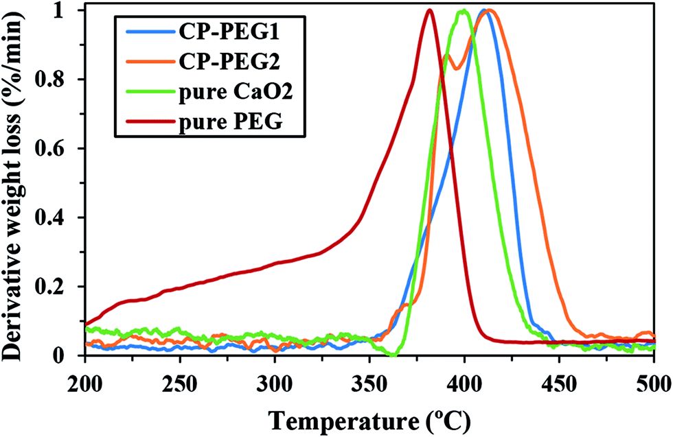 | ||
| Fig. 7 DTG curves of CP-PEG1, CP-PEG2, pure CaO2, and pure PEG. | ||
Fig. 8 depicts the FTIR spectra of the precipitated particles at molar ratio of PEG/calcium of 0.34 and the spectra of the polymer alone in the range 400–4000 cm−1. One of the common absorption peaks between PEG alone and CP-PEG2 was a broadband peak, which is attributed to the stretching mode of the –OH group of the PEG and that of the lattice water molecules of the synthesized calcium peroxide in the spectral region of 3000–3700 cm−1. Moreover, two peaks at 2857 and 2929 cm−1 (–CH2– band),49 1635 cm−1 band of the H–O–H bending of residual free water,50 and C–O–C band at 1076 cm−1 (ref. 23) were common. Consequently, the presence of the bands assigned to PEG in the CP-PEG2 sample and a slight reduction in mass by 5% resulting from PEG degradation in the TGA curve of CP-PEG2 confirmed the adsorption of the polymer onto the particle surface.
 | ||
| Fig. 8 FTIR spectra of PEG alone and PEG stabilized particles (CP-PEG2). | ||
Moreover, the existence of CaO2 and calcite, which XRD and TGA results identified as an impurity of CaO2 synthesis, was also confirmed by FTIR analysis. For example, the absorption peak at 875 cm−1 was attributed to the O–O bridge of CaO2 (ref. 51) and the very weak absorption at 711 cm−1 was due to the vibration of the carbonate ion in calcite (Fig. 8).52 Furthermore, a broad peak in the interval of 1600–1200 cm−1 was caused from the superposition of O–Ca–O of CaO2 and the CO32− group of calcite. Therefore, the smoothed second derivative spectra were calculated to determine the position of the overlapping peaks (Fig. 9). As represented in Fig. 9b, several peaks at 1490, 1440, 1413, and 1384 cm−1 were observed. In fact, those at 1413 and 1490 cm−1 could be associated with the bending vibration mode of O–Ca–O53 and the two peaks at 1440 and 1384 cm−1 corresponded to the CO32− group.53–55
 | ||
| Fig. 9 (a) FTIR spectra and (b) second derivative of CP-PEG2. | ||
In this study, the effective factors on the variation of the measured oxygen concentration in distilled water over a period of 4 days for two inorganic peroxides were determined. Fig. 10a shows the oxygen release kinetics and pH changes of the surrounding medium for the CP-PEG1 and CP-PEG2 particles, as well as for the control sample during the initial minutes. The release profile of PEG-coated CaO2 particles showed an initial burst release of oxygen, in which the dissolved oxygen (DO) of CP-PEG1 and CP-PEG2 could reach nearly 2- and 1.7-fold of dissolved oxygen equilibrium concentration in distilled water within 90 minutes, respectively. This significant burst release was due to the hydrolysis reaction on the surface of the particles with high surface-to-volume ratio and the lack of a diffusional barrier initially. Interestingly, the oxygen saturation level of the CP-PEG1 sample was higher than the CP-PEG2 sample because, according to the TGA results, the calcium peroxide content or available oxygen of CP-PEG1 was higher than that of CP-PEG2.
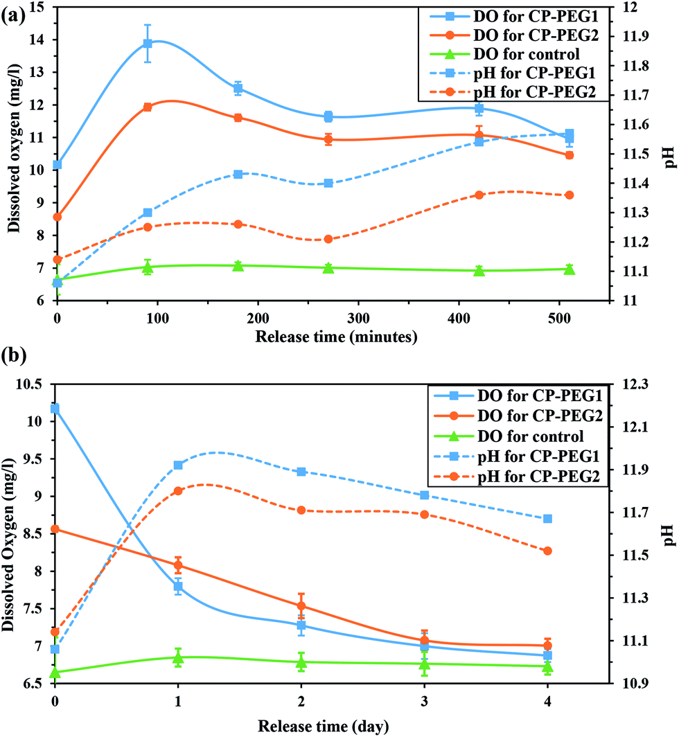 | ||
| Fig. 10 pH variation and release of O2 from two CaO2 samples (a) within 510 minutes and (b) within 4 days. | ||
Moreover, most of the oxygen was released on the first day, and oxygen generation decreased subsequently (Fig. 10b). Two main reasons of oxygen release reduction can be related to:
• According to the Fig. 10a, the pH value in the medium surrounding the particles increased from neutral to 11 within 90 minutes. The pH variation was attributed to the calcium hydroxide generation (a secondary product of the CaO2 hydrolysis). An increase in the pH level of the medium increases the O2 yield, however acts as an inhibitor of the oxygen release process and lower dissolution rate of calcium peroxide.11 Therefore, an increase in the pH value of the exterior medium of two samples caused a noticeable decrease in the oxygen levels.
• Waite et al.10 stated that oxygen release rate is controlled by diffusion through the Ca(OH)2(s) product layer that precipitates during the CaO2 dissolution. However, according to the solubility of Ca(OH)2 in water (0.1620 g/100 g water 56) and 1:1 mole ratio between Ca(OH)2 and CaO2 in the hydrolysis reaction, the amount of ions added in this study was lower than Ca(OH)2 solubility. Alternatively, the declining pH level of the medium after the first day (Fig. 10b) confirmed the gradual decrease of hydroxide ion content due to carbonation. Thus, the rate of oxygen release was controlled by diffusion through the CaCO3 precipitated layer as a result of carbonation of the Ca(OH)2 over time.
As shown in Fig. 10, the oxygen release pattern of CaO2 nanoparticles was biphasic: an initial burst phase for the first 24 hours followed by a descending release rate for three days. The initial burst oxygen release was affected by the nanoparticle characteristics including particle size, particle size distribution, purity of CaO2, and amount of adsorbed PEG. However, the oxygen release rate in the second release phase was slightly affected by the nanoparticle properties; the second phase was mainly controlled by high pH value of the exterior medium and diffusion through the precipitated product layer on the surface of the particles (as discussed previously). Moreover, the precipitation of the product layer and the increase in the pH level of the medium as a result of the significant oxygen production during the initial hours induced a descending oxygen release rate. In order to compare oxygen production by CP-PEG1 and by CP-PEG2 during the two phases, the area under the curve [AUC (0–510 min)] was calculated by the linear trapezoidal rule.57 The level of total oxygen production by the CP-PEG1 particles (28.84 mg l−1) over 510 minutes was higher than that by the CP-PEG2 particles (22.91 mg l−1) possibly due to the higher purity of CP-PEG1. However, the oxygen released by CP-PEG2 (1.83 mg l−1) and CP-PEG1 (1.28 mg l−1) particles substantially declined over the last three days. Decreasing the oxygen generation by CP-PEG1 and CP-PEG2 samples in the second stage confirmed the significant impact of oxygen release controlling factors after burst oxygen release. Therefore, the oxygen release rate of CP-PEG1 and CP-PEG2 samples due to impacts of oxygen release controlling factors was almost the same after the first day.
The statistical comparison between the released oxygen amount of CaO2 particles and the dissolved oxygen in the control sample exhibited a significant O2 level introduced by the CP-PEG2 sample throughout the analysis (p < 0.05), although there was no meaningful difference among the CP-PEG1 and control samples on the third and fourth days (Fig. 11). It is possibly due to the higher adsorption of PEG on the surface of CP-PEG2 particles, which roughly inhibited the agglomeration of particles and thereby boosted the oxygen production capability by virtue of exposing a higher surface area for O2 release. Therefore, a higher amount of adsorbed PEG led to a more sustained oxygen release from the particles.
 | ||
| Fig. 11 Histogram of the released oxygen from two CaO2 samples in distilled water per day. Asterisk represents the significant difference between each other, n = 3 for each group, p < 0.05. | ||
The synthesis of the calcium peroxide particles with smaller size can lead to an increase in oxygen generation ability over a particular time interval (as discussed before). In order to confirm the effect of the CaO2 crystallite size on the oxygen release, the oxygen release behavior of calcium peroxide synthesized with different reactant addition rates of 0.58 (CP2) and 0.88 ml min−1 (CP3) was examined (Fig. 12). The area under the curve [AUC (0–420 min)] was used to evaluate oxygen generation ability within 420 minutes. The level of total oxygen production for CP3 particles (24.02 mg l−1) over 420 minutes was higher compared to that for CP2 particles (15.76 mg l−1) with larger crystallite size. Therefore, the initial oxygen production increased with an increment in the H2O2 addition rate. The oxygen released during the initial hours was probably due to hydrolysis reaction on the surface of the particles. Consequently, smaller crystallites with a higher surface-to-volume ratio as a result of increasing the rate of H2O2 addition led to higher oxygen production over a specific period.
 | ||
| Fig. 12 Release of O2 from synthesized CaO2 with different H2O2 addition rates within 420 minutes. | ||
4. Conclusion
In this study, calcium peroxide particles with oxygen release capability and orthorhombic structure were synthesized via the precipitation reaction of an ammonia calcium chloride solution with hydrogen peroxide. The effect of hydrogen peroxide addition rate as an effective factor on the purity, crystallite size, and particle size distribution of the synthesized CaO2 was inspected. It was found that the H2O2 addition rate affects the purity of the synthesized CaO2. Moreover, smaller crystallites were produced from the solutions with a faster addition rate, so there could be an indirect relationship between the crystallite size and reactant addition rate. The results showed that the slow addition rate could increase the span of distribution due to the Ostwald ripening process; however, the higher local supersaturation could induce diffusion controlled growth and lead to narrower PSD. Additionally, PEG-coated CaO2 particles were achieved by the synthesis of particles directly in PEG medium. The presence of PEG on the surface of CaO2 particles with a higher molar ratio of PEG to calcium was proved by the TGA analysis and FTIR spectroscopy. The PEG-coated particles exhibited an initial burst release of oxygen due to the high surface-to-volume ratio; however, the rate of oxygen release was controlled by diffusion through the precipitated layer over time. Moreover, a more sustained oxygen release from the particles having more amount of adsorbed PEG was identified.Conflicts of interest
There are no conflicts to declare.References
- M. Gholipourmalekabadi, S. Zhao, B. S. Harrison, M. Mozafari and A. M. Seifalian, Trends Biotechnol., 2016, 34, 1010–1021 CrossRef CAS PubMed.
- T. L. Schenck, M. N. Chávez, A. P. Condurache, U. Hopfner, F. Rezaeian, H.-G. Machen and J. T. Egaña, J. Visualized Exp., 2014, 51428 Search PubMed.
- H. Steg, A. T. Buizer, W. Woudstra, A. G. Veldhuizen, S. K. Bulstra, D. W. Grijpma and R. Kuijer, J. Mater. Sci.: Mater. Med., 2015, 26, 1–4 CrossRef CAS PubMed.
- J. Folkman, P. Hahnfeldt and L. Hlatky, Nat. Rev. Mol. Cell Biol., 2000, 1, 76–79 CrossRef CAS PubMed.
- G. Camci-Unal, N. Alemdar, N. Annabi and A. Khademhosseini, Polym. Int., 2013, 62, 843–848 CrossRef CAS PubMed.
- E. Pedraza, M. M. Coronel, C. A. Fraker, C. Ricordi and C. L. Stabler, Proc. Natl. Acad. Sci. U. S. A., 2012, 109, 4245–4250 CrossRef CAS PubMed.
- L. Yang, L. Zhu, W. Dong, Y. Cao and Z. Rong, Bone, 2013, 57, 322–323 CrossRef CAS PubMed.
- A. L. Farris, A. N. Rindone and W. L. Grayson, J. Mater. Chem. B, 2016, 4, 3422–3432 RSC.
- I. I. Volnov, Peroxides, Superoxides, and Ozonides of Alkali and Alkaline Earth Metals, Plenum Press, New York, 1966 Search PubMed.
- A. J. Waite, J. S. Bonner and R. Autenrieth, Environ. Eng. Sci., 1999, 16, 187–199 CrossRef CAS.
- A. Northup and D. Cassidy, J. Hazard. Mater., 2008, 152, 1164–1170 CrossRef CAS PubMed.
- D. P. Cassidy and R. L. Irvine, J. Hazard. Mater., 1999, 69, 25–39 CrossRef CAS PubMed.
- P. Ehrlich, Handbook of preparative inorganic chemistry, G. Brauer, Academic Press, New York, 2nd edn, 1963, ch. 17, vol. 1, pp. 887–949 Search PubMed.
- W. H. Philipp and P. A. Kraft, Annual Meeting of the American Institute of Chemical Engineers, San Francisco, CA, 1989 Search PubMed.
- J. Khodaveisi, H. Banejad, A. Afkhami, E. Olyaie, S. Lashgari and R. Dashti, J. Hazard. Mater., 2011, 192, 1437–1440 CrossRef CAS PubMed.
- S. H. Oh, C. L. Ward, A. Atala, J. J. Yoo and B. S. Harrison, Biomaterials, 2009, 30, 757–762 CrossRef CAS PubMed.
- B. S. Harrison, D. Eberli, S. J. Lee, A. Atala and J. J. Yoo, Biomaterials, 2007, 28, 4628–4634 CrossRef CAS PubMed.
- C. L. Ross, B. Bonfert, L. Smith, S. Y. Jeong and B. S. Harrison, J. Sci. Appl: Biomed., 2015, 3, 1–4 Search PubMed.
- J. Wang, Y. Zhu, H. K. Bawa, G. Ng, Y. Wu, M. Libera, H. C. Van Der Mei, H. J. Busscher and X. Yu, ACS Appl. Mater. Interfaces, 2011, 3, 67–73 CAS.
- H. Steg, A. T. Buizer, W. Woudstra, A. G. Veldhuizen, S. K. Bulstra, D. W. Grijpma and R. Kuijer, Polym. Adv. Technol., 2016, 28, 1252–1257 CrossRef.
- N. G. Rim, C. S. Shin and H. Shin, Biomed. Mater., 2013, 8, 014102 CrossRef PubMed.
- H. W. Kim, H. H. Lee and J. C. Knowles, J. Biomed. Mater. Res., Part A, 2006, 79, 643–649 CrossRef PubMed.
- S. García-Jimeno and J. Estelrich, Colloids Surf., A, 2013, 420, 74–81 CrossRef.
- H. Pardoe, W. Chua-anusorn, T. G. St. Pierre and J. Dobson, J. Magn. Magn. Mater., 2001, 225, 41–46 CrossRef CAS.
- B. R. Jarrett, M. Frendo, J. Vogan and A. Y. Louie, Nanotechnology, 2007, 18, 035603 CrossRef PubMed.
- S. A. Simakov and Y. Tsur, J. Nanopart. Res., 2007, 9, 403–417 CrossRef CAS.
- A. S. Karakoti, S. Das, S. Thevuthasan and S. Seal, Angew. Chem., Int. Ed., 2011, 50, 1980–1994 CrossRef CAS PubMed.
- R. A. Sperling and W. J. Parak, Philos. Trans. R. Soc., A, 2010, 368, 1333–1383 CrossRef CAS PubMed.
- P. Kaewdee, N. Chandet, G. Rujijanagul and C. Randorn, Catal. Commun., 2016, 84, 151–154 CrossRef CAS.
- Z. Xuefei, Z. Alec, Q. Yajie, Z. Jing, C. Jiabin and H. Haiping, CN Pat., CN103601155 A, 2014.
- Z. Xuefei, Z. Alec, Z. Jing, Q. Yajie and H. Haiping, CN Pat., CN103964395 A, 2014.
- M. Kaszuba, D. McKnight, M. T. Connah, F. K. McNeil-Watson and U. Nobbmann, J. Nanopart. Res., 2008, 10, 823–829 CrossRef CAS.
- Malvern Instruments Ltd., Zetasizer nano series user manual, 2013 Search PubMed.
- X. Zhao, M. C. Nguyen, C.-Z. Wang and K.-M. Ho, RSC Adv., 2013, 3, 22135–22139 RSC.
- C. Suryanarayana and M. Grant Norton, X-Ray Diffraction A practical Approach, Springer, New York, 1998 Search PubMed.
- B. D. Cullity, Elements of X Ray Diffraction, Addison-Wesley Publishing Company, Inc., 2nd edn, 1978, pp. 281–285 Search PubMed.
- V. Mote, Y. Purushotham and B. Dole, J. Theor. Appl. Phys., 2012, 6, 1–8 CrossRef.
- M. A. Larson and J. Garside, Chem. Eng. Sci., 1986, 41, 1285–1289 CrossRef CAS.
- E. Kramer, J. Podurgiel and M. Wei, Mater. Lett., 2014, 131, 145–147 CrossRef CAS.
- L. Suber, I. Sondi, E. Matijević and D. V. Goia, J. Colloid Interface Sci., 2005, 288, 489–495 CrossRef CAS PubMed.
- K. Lu, Nanoparticulate Materials: Synthesis, Characterization, and Processing, Wiley, Hoboken, 2012 Search PubMed.
- D. Chicea, E. Indrea and C. M. Cretu, J. Optoelectron. Adv. Mater., 2012, 14, 460–466 CAS.
- M. V. Sujitha and S. Kannan, Spectrochim. Acta, Part A, 2013, 102, 15–23 CrossRef CAS PubMed.
- G. K. Soon and T. Hyeon, Acc. Chem. Res., 2008, 41, 1696–1709 CrossRef PubMed.
- J. Luan, J. Zhang, X. Yao, F. Li and B. Jia, Ceram. Int., 2016, 42, 16262–16265 CrossRef CAS.
- G. M. Gurgel, L. X. Lovisa, O. L. A. Conceição, M. S. Li, E. Longo and C. A. Paskocimas, J. Mater. Sci., 2017, 52, 4608–4620 CrossRef CAS.
- Reproducible Step Evaluation for TGA Curves, http://www.mt.com/es/en/home/supportive_content/matchar_apps/MatChar_HB415.html, accessed Jan 2017.
- T. Kim and J. Olek, Transp. Res. Rec., 2012, 2290, 10–18 CrossRef CAS.
- D. L. Pavia, G. M. Lampman, G. S. Kriz and J. R. Vyvyan, Introduction to Spectroscopy, Cengage Learning, 5th edn, 2014 Search PubMed.
- L. Tortet, J. R. Gavarri, G. Nihoul and A. J. Dianoux, J. Solid State Chem., 1997, 132, 6–16 CrossRef CAS.
- J. Żegliński, G. P. Piotrowski and R. Piękoś, J. Mol. Struct., 2006, 794, 83–91 CrossRef.
- F. A. Andersen and L. Brecevic, Acta Chem. Scand., 1991, 45, 1018–1024 CrossRef CAS.
- S. Yan, M. Kim, S. O. Salley and K. S. Ng, Appl. Catal., A, 2009, 360, 163–170 CrossRef CAS.
- Z. Y. Zhou, N. Tian, Y. J. Chen, S. P. Chen and S. G. Sun, J. Electroanal. Chem., 2004, 573, 111–119 CAS.
- M. Derrick, D. Stulik and J. Landry, Infrared spectroscopy in conservation science, Getty Publications, Los Angeles, 2000 Search PubMed.
- CRC Handbook of Chemistry and Physics, ed. D. R. Lide, CRC Press, Boca Raton, 84th edn, 2003 Search PubMed.
- J. C. Pruessner, C. Kirschbaum, G. Meinlschmid and D. H. Hellhammer, Psychoneuroendocrinology, 2003, 28, 916–931 CrossRef CAS PubMed.
| This journal is © The Royal Society of Chemistry 2018 |