Well-aligned metal–organic framework array-derived CoS2 nanosheets toward robust electrochemical water splitting†
Na
Yao
,
Tan
Tan
,
Fulin
Yang
,
Gongzhen
Cheng
and
Wei
Luo
 *
*
College of Chemistry and Molecular Sciences, Wuhan University, Wuhan, Hubei 430072, P. R. China. E-mail: wluo@whu.edu.cn
First published on 31st July 2018
Abstract
Exploring high-efficiency and stable nonprecious bifunctional electrocatalysts for the hydrogen evolution reaction (HER) and the oxygen evolution reaction (OER) is highly desirable but still challenging. Herein, we develop a versatile approach for the rational design and fabrication of highly open three-dimensional (3D) hierarchical architectures composed of two-dimensional (2D) CoS2 nanosheets grown on carbon cloth (CoS2 NS/CC) by vulcanizing well-aligned MOF-array precursors. Benefiting from the unique morphology with a high surface area, high density of active sites, and enhanced mass/electrolyte transfer, as well as facile release of the evolved gas, the as-synthesized CoS2 NS/CC exhibits superior catalytic performance and excellent durability for both the HER and OER. Furthermore, when used as a bifunctional electrocatalyst toward overall water splitting, a low cell voltage of 1.58 V is achieved at the current density of 10 mA cm−2 with long-term stability.
Introduction
With growing concerns over the energy crisis and environmental contamination, continuous efforts have been devoted to developing clean and renewable energy conversion and storage technologies. Hydrogen, owing to its high energy density and environmental benignity, has emerged as a promising alternative to traditional fossil fuels. Electrocatalytic overall water splitting has been regarded as a promising approach to produce hydrogen with high purity through two half-reactions, namely, the hydrogen evolution reaction at the cathode and the oxygen evolution reaction at the anode.1–6 However, water splitting suffers from very sluggish kinetics due to the involvement of multiproton-coupled electron-transfer steps. So far, Pt and IrOx are still considered as state-of-the-art catalysts toward the HER and OER, respectively. However, their high cost and low abundance severely limit their widespread applications.7–12 Consequently, a great deal of effort has been devoted to developing non-noble metal based electrocatalysts toward the HER and OER, including earth-abundant first-row transition metal (Co, Ni, Fe, V, and Mn)-based oxides, alloys, carbides, nitrides, phosphides, and chalcogenides.13–34 Among these, transition metal sulfides (TMSs), especially metallic cobalt pyrite (CoS2),35,36 have been extensively explored as promising catalysts for the HER. However, their catalytic performances toward the OER are still unsatisfactory, which hinders their practical applications as bifunctional electrocatalysts for overall water splitting.Recently, two-dimensional (2D) TMSs have received considerable attention due to the advantages derived from unique 2D architectures. (i) The exposed surface atoms of 2D sheets can escape from the lattice easily, resulting in the formation of defects strongly affecting their electronic structures and thus increasing the number of active sites; (ii) the 2D nanomaterials will favor the electron transfer rate during electrocatalysis; (iii) the electrons in the 2D material are constrained to adopt a 2D wave function with electronic properties that greatly differ from other materials and might change the electronic energy band structure through Klein tunnel effects and half-integer quantum Hall effects, thereby reducing the bandgap of 2D materials, resulting in increased conductivity.37–42 On the other hand, metal–organic frameworks (MOFs), due to their high porosity and surface area, and their well-tunable chemical structures and morphologies, have been considered as versatile templates and precursors to construct TMSs with unique architectures. However, the direct pyrolysis of MOFs in their powder forms typically causes undesirable and irreversible aggregation, resulting in the unfavorable transport of mass/electrolyte as well as evolved gas release during the catalysis.43–55 To this end, Zhang and coworkers reported a mesoporous-silica-protected calcination method to fabricate hierarchically porous Co,N–CNF with high electrocatalytic activity for the oxygen reduction reaction (ORR).56 Very recently, our group reported the synthesis of a S-Co9−xFexS8@rGO hybrid through semi-vulcanization and calcination of graphene oxide (GO) wrapped bimetallic MOFs with superior catalytic performance for the ORR and OER.57 Since these synthetic methods involve a complicated procedure, consequently, a simple and convenient route to fabricate MOF-derived TMSs with the desired catalytic activity is highly desirable.
Herein, by directly growing well-aligned MOF arrays throughout a conductive matrix (carbon cloth, CC), we report the straightforward synthesis of two-dimensional (2D) CoS2 nanosheets (CoS2 NS/CC), which are further interconnected with each other to form a highly open three-dimensional (3D) hierarchical architecture. As expected, the CoS2 NS/CC exhibits remarkable catalytic activity toward the OER and HER, with overpotentials of 220 and 90 mV to drive the current density of 10 mA cm−2, and long-term durability. Moreover, when used as both the anode and cathode for overall water splitting, the current density of 10 mA cm−2 is achieved at a cell voltage of 1.58 V under alkaline media.
Experimental
Materials
All chemicals were analytical grade and used without further purification. Deionized water was used as the reaction solvent.Cobalt nitrate hexahydrate (Co(NO3)2·6H2O), urea, ammonium fluoride, sulfur powder and ammonium bicarbonate were all purchased from Sinopharm Chemical Reagent Co., Ltd. Carbon cloth (CC) was purchased from CeTech Co., Ltd. 2-Methylimidazole was bought from Sigma-Aladdin and Pt–C (Johnson Mattey Hispec 3600) was from Shanghai Hesen Electric Co., Ltd.
Synthesis of Co(OH)F nanoarrays
The carbon cloth was pretreated with mixed HNO3 and H2SO4 solution (1![[thin space (1/6-em)]](https://www.rsc.org/images/entities/char_2009.gif) :
:![[thin space (1/6-em)]](https://www.rsc.org/images/entities/char_2009.gif) 1) to remove the hydrophobicity and impurities on the surface, and further cleaned by sonicating in deionized water, ethanol and acetone for 30 minutes, respectively. Co(OH)F nanoarrays were prepared on the carbon cloth via a facile hydrothermal method. In a typical procedure, 1 mmol Co(NO3)2·6H2O, 4 mmol NH4F and 5 mmol urea were dissolved in 36 mL DI water. After stirring for about 20 min, a transparent pink colored solution was obtained. The homogeneous solution and a piece of carbon cloth (2 × 2 cm2) were transferred into a 100 mL Teflon-lined autoclave in an electric oven, sealed and kept at 100 °C for 8 h. The as-synthesized Co(OH)F nanoarrays were cleaned with water and ethanol several times, and then dried at 80 °C under vacuum overnight.
1) to remove the hydrophobicity and impurities on the surface, and further cleaned by sonicating in deionized water, ethanol and acetone for 30 minutes, respectively. Co(OH)F nanoarrays were prepared on the carbon cloth via a facile hydrothermal method. In a typical procedure, 1 mmol Co(NO3)2·6H2O, 4 mmol NH4F and 5 mmol urea were dissolved in 36 mL DI water. After stirring for about 20 min, a transparent pink colored solution was obtained. The homogeneous solution and a piece of carbon cloth (2 × 2 cm2) were transferred into a 100 mL Teflon-lined autoclave in an electric oven, sealed and kept at 100 °C for 8 h. The as-synthesized Co(OH)F nanoarrays were cleaned with water and ethanol several times, and then dried at 80 °C under vacuum overnight.
Synthesis of ZIF-67 nanorods
The ZIF-67 nanorods were prepared by a facile step. In general, 0.82 g of 2-methyldazole was dissolved in 5 mL of methanol and 5 mL of ethanol, and then a piece of Co(OH)F/CC obtained was immersed into the solution, which was maintained at room temperature for 2 days until the surface of the carbon cloth became dark blue. The sample was then dried at room temperature under vacuum.Synthesis of CoS2 flower-like nanosheets and CoS2 flower-like nanosticks
The CoS2 flower-like nanosheets and CoS2 flower-like nanosticks were both prepared by a traditional CVD method. In general, 0.1 g of sulfur powder and 1.0 g of ammonium bicarbonate were placed separately on the bottom and in the middle of the quartz tube, and then a piece of ZIF-67/CC (loading amounts: 4.0 mg cm−2) was placed on the nozzle of a quartz tube and sealed with aluminum foil before heating in a tube furnace at 300 °C for 2 h under a N2 atmosphere. The heating speed was kept at 2 °C min−1. The as-prepared CoS2/CC flower-like nanosheets were immersed in 0.5 M H2SO4 and deionized for a while, followed by washing with deionized water and ethanol and dried at 20 °C in a vacuum pump. The CoS2 flower-like nanosticks were prepared by means of the same steps as above with Co(OH)F/CC.Characterization
Powder X-ray diffraction (XRD) patterns were obtained on a Bruker D8-Advance X-ray diffractometer using a Cu Kα radiation source (λ = 0.154178 nm) with a velocity of 10° min−1. The morphologies and sizes of the samples were observed by using a Tecnai G20 U-Twin transmission electron microscope (TEM). X-ray photoelectron spectroscopy (XPS) measurements were recorded on a Thermo Fischer ESCALAB 250Xi spectrophotometer with an aluminum excitation source.Electrochemical measurements
The electrocatalytic activities of all the samples were measured on a CHI 760E electrochemical station in a three-electrode configuration at room temperature. The electrolyte solution was 1.0 M KOH, with CoS2 NS/CC as the working electrode. The loading amount of CoS2 NS/CC was ∼3.5 mg cm−2, with a carbon rod as the counter electrode and a Hg/HgO electrode as the reference electrode. The mass loading for Co(OH)F/CC, ZIF-67/CC and CoS2 NR/CC was similar. Pt/C was dispersed in isopropanol solvent (0.1% Nafion), and the catalytic ink (5 mg mL−1) was deposited onto the carbon cloth (0.4 × 0.5 cm2) with an overall catalyst loading of 2 mg cm−2. The actual value of the potential vs. reversible hydrogen electrode (RHE) of the Hg/HgO electrode was calibrated by using 20 wt% Pt/C deposited onto the glassy carbon as the working electrode to obtain the hydrogen oxidation reaction polarization curve at 5 mV s−1 under a H2 atmosphere.Before the electrochemical test, the working electrode was activated at 500 mV s−1 for several cycles. Linear sweep voltammetry (LSV) was carried out at 5 mV s−1. Cyclic voltammetry (CV) and chronopotentiometric curves were obtained to explore the stability of the working electrode.
Results and discussion
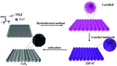
The synthetic method of CoS2 NS/CC is schematically illustrated in Scheme 1. Briefly, Co(OH)F nanowire arrays grown on carbon cloth (Co(OH)F/CC) were first prepared by a hydrothermal method.58 Then, the Co(OH)F/CC was converted into ZIF-67/CC by soaking in a methanol and ethanol (1![[thin space (1/6-em)]](https://www.rsc.org/images/entities/char_2009.gif) :
:![[thin space (1/6-em)]](https://www.rsc.org/images/entities/char_2009.gif) 1) solution of 2-methyl imidazole. The CoS2 nanosheets (CoS2 NS/CC) were obtained by vulcanizing ZIF-67/CC with sulfur (see more detailed information in the Experimental section).59 The crystal structures of Co(OH)F/CC, ZIF-67/CC, and the resultant CoS2 NS/CC were further confirmed by X-ray diffraction (XRD) analysis as shown in Fig. S1 and S2 (ESI†), and Fig. 1a. Typical diffraction peaks corresponding to Co(OH)F/CC, and ZIF-67/CC are observed, suggesting the successful formation of Co(OH)F/CC, and transformation to ZIF-67/CC. Five characteristic peaks located at 27.9°, 32.3°, 36.2°, 46.3°, 49.3° and 54.9° can be assigned to the (111), (200), (210), (211) and (220) planes of CoS2 (JCPDS No. 41-1471), respectively.
1) solution of 2-methyl imidazole. The CoS2 nanosheets (CoS2 NS/CC) were obtained by vulcanizing ZIF-67/CC with sulfur (see more detailed information in the Experimental section).59 The crystal structures of Co(OH)F/CC, ZIF-67/CC, and the resultant CoS2 NS/CC were further confirmed by X-ray diffraction (XRD) analysis as shown in Fig. S1 and S2 (ESI†), and Fig. 1a. Typical diffraction peaks corresponding to Co(OH)F/CC, and ZIF-67/CC are observed, suggesting the successful formation of Co(OH)F/CC, and transformation to ZIF-67/CC. Five characteristic peaks located at 27.9°, 32.3°, 36.2°, 46.3°, 49.3° and 54.9° can be assigned to the (111), (200), (210), (211) and (220) planes of CoS2 (JCPDS No. 41-1471), respectively.
The morphologies of these samples were characterized by scanning electron microscopy (SEM). As shown in Fig. S3 (ESI†), the nanoneedles in sea urchin-like Co(OH)F are changed to well-extended nanorod arrays after the formation of ZIF-67, while some of the nanorods are ready to aggregate. Fig. 1b shows that the as-synthesized CoS2 nanosheets are composed of 2D nanosheets, which are interconnected to form a highly open 3D hierarchical architecture. Further insights into the microstructure and elemental composition information of CoS2 were studied by transmission electron microscopy (TEM) and high angle annular dark field scanning transmission electron microscopy (HAADF-STEM). The TEM in Fig. 1c further indicates the formation of 2D nanosheets. The HRTEM in Fig. 1d indicates two different lattices with spacing distances of 0.25 nm and 0.27 nm, which can be ascribed to the (211) and (200) planes of the CoS2, respectively. In addition, the energy dispersive spectroscopy (EDS) shown in Fig. S6 (ESI†) indicates the co-existence of Co and S in the nanosheet. Furthermore, HAADF-STEM in Fig. 1e and the corresponding elemental mapping (Fig. 1f) confirm the uniform distribution of Co, S, N and C elements within the whole nanosheet.
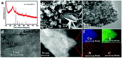 | ||
| Fig. 1 (a) XRD pattern and (b) SEM, (c) TEM, (d) HRTEM and (e) HAADF-STEM images of CoS2 NS/CC, and (f) the corresponding element mapping images of the selected area in (e). | ||
To get an in-depth understanding of the formation mechanism of 2D nanosheets, the growth process of CoS2 was investigated at different reaction times. As shown in Fig. S4a (ESI†), more uneven bigger nanorods are formed and ready to interconnect at the end of a 30 min reaction. Afterward, the formation of nanosheet-like CoS2 can be clearly seen after 60 and 90 min as shown in Fig. S4b and c (ESI†). Finally, the CoS2 nanosheets subsequently self-assemble into a highly open 3D hierarchical architecture to minimize their surface energy at a relatively high temperature.32 For comparison, nanorod arrays of CoS2 were synthesized by directly vulcanizing the Co(OH)F precursor (denoted as CoS2 NR/CC). The XRD and SEM CoS2 NR/CC are shown in Fig. S5 (ESI†), indicating that the MOF-template synthetic method is key for the formation of 2D CoS2 nanosheets with 3D hierarchical architecture. In addition, 2D NiS2 and FeS2 have been synthesized through a similar method, suggesting a universal strategy for fabricating other 2D MOFs and derived TMSs (Fig. S7, ESI†).
The chemical and valence states of CoS2 NS/CC were also detected by X-ray photoelectron spectroscopy (XPS). As shown in Fig. 2a, the XPS survey result indicates that CoS2 NS/CC is composed of Co, S, N, and C elements, which is consistent with the TEM and STEM results. In the high-resolution core spectrum of Co 2p (Fig. 2b), peaks located at 778.1 and 793.1 eV, corresponding to Co–S are observed. The other two peaks located at 780.2 and 796.2 eV are consistent with the S–Co–O bond, which might be caused by the surface oxidation of CoS2. The other two peaks are associated with shakeup satellites.36,57,61 In the S region (Fig. 2c), two characteristic peaks located at 161.3 and 162.4 eV can be assigned to the 2p core levels of S–Co in typical CoS2 species. Moreover, peaks located at 163.2 and 164.3 eV can be attributed to the S–S bond in cobalt sulfides. The peaks located at 166.8 and 168.0 eV are contributed by S–S, which is usually observed in CoS2. In addition, in the N 1s spectrum of CoS2 NS/CC (Fig. 2d), three peaks located at 398.2, 399.2 and 400.2 eV can be assigned to C![[double bond, length as m-dash]](https://www.rsc.org/images/entities/char_e001.gif) N, N–H, and N–Co–S, respectively.48,49,60,62
N, N–H, and N–Co–S, respectively.48,49,60,62
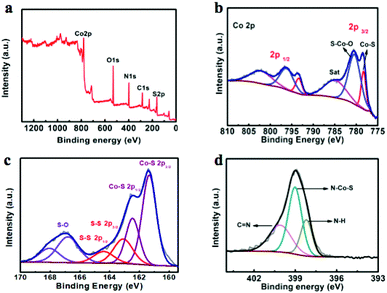 | ||
| Fig. 2 (a) XPS survey of CoS2 NS/CC; high-resolution XPS images of (b) Co 2p; (c) S 2p; and (d) N 1s. | ||
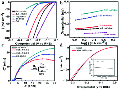
The HER activity of the as-synthesized CoS2 NS/CC was evaluated in a three-electrode system by linear sweep voltammetry (LSV) under 1 M KOH. For comparison, CoS2 NR/CC, ZIF-67/CC, Co(OH)F/CC, and commercial Pt/C (20 wt%) were also investigated. As shown in Fig. 3a, Pt/C exhibits the highest catalytic activity, which only requires an overpotential of 35 mV to achieve a current density of 10 mA cm−2. As limited by the intrinsic activity, Co(OH)F/CC and ZIF-67/CC exhibit a much inferior HER performance, with overpotentials of 270 and 200 mV to deliver the current density of 10 mA cm−2, respectively. As expected, the as-synthesized CoS2 NS/CC exhibits much enhanced activity, with an overpotential of 90 mV at 10 mA cm−2, which is much lower than that of CoS2 NR/CC (125 mV). It is worth noting that the catalytic performance of the as-synthesized CoS2 NS/CC is better than most of the reported TMS-based HER catalysts as shown in Table S1 (ESI†). In addition, the Tafel slopes of these samples were also calculated and are displayed in Fig. 3b. CoS2 NS/CC exhibits a small slope of 48 mV dec−1, which is much lower than those of CoS2 NR/CC (72 mV dec−1), ZIF-67 (137 mV dec−1) and Co(OH)F (136 mV dec−1), and comparable to that of Pt/C (30 mV dec−1), suggesting the superior HER catalytic kinetics. As displayed in Fig. 3c, after 1000 cycles of CV measurement with the potential between −0.9 and −1.25 V, CoS2 NS/CC shows a negligible decrease compared to the initial curve. In addition, the chronopotentiometric curve indicates that CoS2 NS/CC can maintain a current density of 10 mA cm−2 over a period of 40![[thin space (1/6-em)]](https://www.rsc.org/images/entities/char_2009.gif) 000 s, indicating the superior stability in long-term HER catalysis.
000 s, indicating the superior stability in long-term HER catalysis.
Moreover, to further investigate the differences between these samples, the charge transfer resistance (Rct) and electrochemical surface area (ECSA) were also investigated, by using the electrochemical impedance spectrum (EIS) and double-layer capacitance (Cdl) through cyclic voltammetry (CV). As shown in Fig. 3d, CoS2 NS/CC has the smallest Nyquist semicircle diameter among all the tested samples, suggesting that CoS2 NS/CC has the smallest Rct, possessing the most favorable electron transfer process during the HER process. In addition, CoS2 NS/CC has a Cdl of 252 mF cm−2, which is much higher than those of CoS2 NR/CC (120 mF cm−2) and ZIF-67/CC (6 mF cm−2), as shown in Fig. S8 (ESI†), suggesting more active site exposure of CoS2 NS/CC. Based on the previously reported density functional theory (DFT) calculations, the Gibbs free energy of hydrogen absorption (ΔGH*) on the edge site of CoS2 is much smaller than that of bulk CoS2.43,63,64 It is thus expected that more active edge sites might be formed/exposed in the 2D CoS2 NS/CC, resulting in enhanced HER activity.
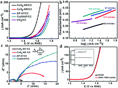
The OER activities of these samples were further studied in a three-electrode system by LSV in 1 M KOH. As shown in Fig. 4a, the as-synthesized CoS2 NS/CC exhibits the highest OER activity among all the catalysts tested. In particular, it needs an overpotential of 220 mV to drive the current density of 10 mA cm−2, which is much lower than those of CoS2 NR/CC (270 mV), Co(OH)F/CC (340 mV), and ZIF-67/CC (320 mV), and also lower than that of commercial IrO2 (300 mV). It should be noted that the catalytic performance of CoS2 NS/CC is much higher than those of the reported TMS-based OER catalysts and higher than most of the non-precious metal based electrocatalysts as indicated in Table S2 (ESI†). In addition, the CoS2 NS/CC presents a Tafel slope of 92 mV dec−1, much lower than those of CoS2 NR/CC (137 mV dec−1), ZIF-67/CC (97 mV dec−1) and Co(OH)F (106 mV dec−1) as indicated in Fig. 4b. Moreover, the EIS and ESCA of those samples are also tested to get further details of the electron transfer kinetics during the OER process. As expected, CoS2 NS/CC possesses the smallest charge transfer resistance among all the catalysts tested (Fig. 4c). For the ECSA measurements, as shown in Fig. S9 (ESI†), the Cdl of CoS2 NS/CC is measured to be 97 mF cm−2, much higher than those of CoS2 NR/CC (10.8 mF cm−2), and ZIF-67 (13.8 mF cm−2), suggesting the best electron conductivity and the relatively large active area of CoS2 NS. In addition, after 1000 cycles of the CV measurement with the potential between 0.3 and 0.85 V, there is almost no decrease between the initial and final CVs of the CoS2 NS/CC as shown in Fig. 4d. Furthermore, as shown in the chronopotentiometric curve, the catalytic performance of OER remains nearly unchanged after 15 h, indicating the superior stability of CoS2 NS/CC for the long-term OER process. After the OER tests, the CoS2 NS/CC still maintained the nanosheet structure (Fig. S10, ESI†). The XPS spectrum shown in Fig. S11 (ESI†) indicates the formation of cobalt oxyhydroxide (Co3+) on the surface of CoS2 NS/CC, suggesting the catalytic capability might originate from the formation of CoOOH on the surface of the catalysts as indicated in previous reports.38,39 Moreover, CoS2 without using carbon cloth was also synthesized. As shown in Fig. S12 (ESI†), bulk CoS2 with severe aggregation was observed, and the resultant HER and OER performances are both inferior to those of CoS2 NS/CC.
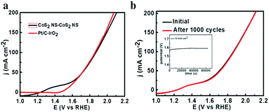
Encouraged by the excellent HER and OER performances, we built an alkaline electrolyzer using CoS2 NS/CC as both the anode and cathode. As shown in Fig. 5, the CoS2 NS/CC achieves a current density of 10 mA cm−2 at 1.58 V, which is smaller than that of IrO2/CC||Pt/C/CC (1.62 V) and most of the reported self-supported water-splitting devices (as shown in Table S3, ESI†). As shown in Fig. 5b, no obvious decay is observed for the CoS2 NS/CC after 1000 cycles. Furthermore, it shows almost no degradation after continuous electrolysis for 80![[thin space (1/6-em)]](https://www.rsc.org/images/entities/char_2009.gif) 000 s, suggesting a superior long-term electrochemical stability. In addition, the faraday efficiencies of O2 and H2 production were also measured, which fit well with the theoretical yields with the molar ratio of H2 to O2, indicating a faraday efficiency of almost 99% (Fig. S13, ESI†).
000 s, suggesting a superior long-term electrochemical stability. In addition, the faraday efficiencies of O2 and H2 production were also measured, which fit well with the theoretical yields with the molar ratio of H2 to O2, indicating a faraday efficiency of almost 99% (Fig. S13, ESI†).
Conclusion
In summary, we have demonstrated a versatile approach for the rational design and fabrication of 2D CoS2 nanosheets grown on carbon cloth (CoS2 NS/CC) through a sulfidation process derived from well aligned MOF-array precursors.These transparent nanosheets further self-assemble into highly open 3D hierarchical architectures. We found that the MOF-template synthetic method is essential for the formation of this unique architecture, while directly vulcanizing Co(OH)F precursor results in CoS2 nanorod arrays. Thanks to the unique 3D highly open hierarchical architecture of CoS2 NS with high exposure of active sites, as well as the enhanced release of evolved gas, the resultant CoS2 NS/CC exhibits a much enhanced catalytic performance toward the HER and OER, with overpotentials of 220 and 90 mV to achieve a current density of 10 mA cm−2, and superior long-term durability. Moreover, when used as bifunctional electrocatalysts for overall water splitting, it affords a current density of 10 mA cm−2 at a cell voltage of 1.58 V under alkaline media. It is expected that the direct growth of well-aligned MOF arrays throughout a conductive matrix might open up a new avenue for the rational design of other MOF-derived materials for more applications.
Conflicts of interest
There are no conflicts to declare.Acknowledgements
This work was financially supported by the National Natural Science Foundation of China (21571145, 21633008), and the Large-Scale Instrument and Equipment Sharing Foundation of Wuhan University.Notes and references
- X. Liu, W. Xi, C. Li, X. B. Li, J. Shi, Y. L. Shen, J. He, L. Zhang, L. Xie, X. M. Sun, P. Wang, J. Luo, L. M. Liu and Y. Ding, Nano Energy, 2018, 44, 371 CrossRef.
- B. Zhang, X. Zheng, O. Voznyy, R. Comin, M. Bajdich, M. Garcia-Melchor, L. Han, J. Xu, M. Liu, L. Zheng, F. P. Garcia de Arquer, C. T. Dinh, F. Fan, M. Yuan, E. Yassitepe, N. Chen, T. Regier, P. Liu, Y. Li, P. De Luna, A. Janmohamed, H. L. Xin, H. Yang, A. Vojvodic and E. Sargent, Science, 2016, 352, 333 CrossRef PubMed.
- C. Lyu, J. Zheng, R. Zhang, R. Zou, B. Liu and W. Zhou, Mater. Chem. Front., 2018, 2, 323 RSC.
- Y. Lei, L. Wei, S. Zhai, Y. Wang, H. Karahan, X. Chen, Z. Zhou, C. Wang, X. Sui and Y. Chen, Mater. Chem. Front., 2017, 1, 2541 RSC.
- M. Asnavandi and C. Zhao, Mater. Chem. Front., 2018, 2, 323 RSC.
- X. Zou and Y. Zhang, Chem. Soc. Rev., 2015, 44, 5148 RSC.
- K. Liu, H. Zhong, F. Meng, X. Zhang, J. Yan and Q. Jiang, Mater. Chem. Front., 2017, 1, 2155 RSC.
- J. Liu, Y. Zheng, Y. Jiao, Z. Wang, Z. Lu, A. Vasileff and S.-Z. Qiao, Small, 2018, 14, 1704073 CrossRef PubMed.
- X. Zou, Y. Liu, G. D. Li, Y. Wu, D. P. Liu, W. Li, H. W. Li, D. Wang, Y. Zhang and X. Zou, Adv. Mater., 2017, 29, 1700404 CrossRef PubMed.
- X. Jia, Y. Zhao, G. Chen, L. Shang, R. Shi, X. Kang, G. I. N. Waterhouse, L. Z. Wu, C. H. Tung and T. Zhang, Adv. Energy Mater., 2016, 6, 1502585 CrossRef.
- F. Yang, Y. Chen, G. Cheng, S. Chen and W. Luo, ACS Catal., 2017, 7, 3824 CrossRef.
- J. Lai, S. Li, F. Wu, M. Saqib, R. Luque and G. Xu, Energy Environ. Sci., 2016, 9, 1210 RSC.
- J. Zhang, T. Wang, D. Pohl, B. Rellinghaus, R. Dong, S. Liu, X. Zhuang and X. Feng, Angew. Chem., Int. Ed., 2016, 55, 6702 CrossRef PubMed.
- H. Wang, H. W. Lee, Y. Deng, Z. Lu, P. C. Hsu, Y. Liu, D. Lin and Y. Cui, Nat. Commun., 2015, 6, 7261 CrossRef PubMed.
- C. Niether, S. Faure, A. Bordet, J. Deseure, M. Chatenet, J. Carrey, B. Chaudret and A. Rouet, Nat. Energy, 2018, 3, 41560 Search PubMed.
- N. Han, K. R. Yang, Z. Lu, Y. Li, W. Xu, T. Gao, Z. Cai, Y. Zhang, V. S. Batista, W. Liu and X. Sun, Nat. Commun., 2018, 9, 924 CrossRef PubMed.
- X. Fan, Y. Liu, S. Chen, J. Shi, J. Wang, A. Fan, W. Zan, S. Li, W. A. Goddard III and X. M. Zhang, Nat. Commun., 2018, 9, 1809 CrossRef PubMed.
- A. Sahasrabudhe, H. Dixit, R. Majee1 and S. Bhattacharyya, Nat. Commun., 2018, 9, 2014 CrossRef PubMed.
- J. Huang, Y. Sun, Y. Zhang, G. Zou, C. Yan, S. Cong, T. Lei, X. Dai, J. Guo, R. Lu, Y. Li and J. Xiong, Adv. Mater., 2017, 11, 1705045 Search PubMed.
- D. Delgado, M. Minakshi, J. McGinnity and D. J. Kim, Sci. Rep., 2015, 5, 15208 CrossRef PubMed.
- K. Jin, A. Chu, J. Park, D. Jeong, S. E. Jerng, U. Sim, H. Y. Jeong, C. W. Lee, Y.-S. Park, K. D. Yang, G. K. Pradhan, D. Kim, N.-E. Sung, S. H. Kim and K. T. Nam, Sci. Rep., 2015, 5, 10279 CrossRef PubMed.
- X. Zou and Y. Zhang, Chem. Soc. Rev., 2015, 44, 5148 RSC.
- C. Li, X. Han, F. Cheng, Y. Hu, Ch. Chen and J. Chen, Nat. Commun., 2015, 6, 7345 CrossRef PubMed.
- Y. Lin, L. He, T. Chen, D. Zhou, L. Wu, X. Hou and C. Zheng, J. Mater. Chem. A, 2018, 6, 4088 RSC.
- M. Zeng and Y. Li, J. Mater. Chem. A, 2015, 3, 14942 RSC.
- X. Y. Yu and X. W. Lou, Adv. Energy Mater., 2017, 8, 1701592 CrossRef.
- P. W. Menezes, C. Panda, S. Loos, F. Bunschei-Bruns, C. Walter, M. Schwarze, X. Deng, H. Dau and M. Driess, Energy Environ. Sci., 2018, 11, 1287 RSC.
- X. Li, X. Hao, A. Abudulaa and G. Guan, J. Mater. Chem. A, 2016, 4, 11973 RSC.
- Y. Liu, Q. Li, R. Si, G.-D. Li, W. Li, D.-P. Liu, D. Wang, L. Sun, Y. Zhang and X. Zou, Adv. Mater., 2017, 29, 1606200 CrossRef PubMed.
- W. Liu, E. Hu, H. Jiang, Y. Xiang, Z. Weng, M. Li, Q. Fan, X. Yu, E. I. Altman and H. Wang, Nat. Commun., 2016, 7, 10771 CrossRef PubMed.
- Y. Hou, M. Qiu, G. Nam, M. G. Kim, T. Zhang, K. Liu, X. Zhuang, J. Cho, C. Yuan and X. Feng, Nano Lett., 2017, 17, 4202 CrossRef PubMed.
- M. Chauhan, K. P. Reddy, C. S. Gopinath and S. Deka, ACS Catal., 2017, 7, 5871 CrossRef.
- J. Liu, D. Zhu, T. Ling, A. Vasileff and S.-Z. Qiao, Nano Energy, 2017, 40, 264 CrossRef.
- T. Ling, D.-Y. Yan, H. Wang, Y. Jiao, Z. Hu, Y. Zheng, L. Zheng, J. Mao, H. Liu, X.-W. Du, M. Jaroniec and S.-Z. Qiao, Nat. Commun., 2017, 8, 1509 CrossRef PubMed.
- Q. Wang, R. Zou, W. Xia, J. Ma, B. Qiu, A. Mahmood, R. Zhao, Y. Yang, D. Xia and Q. Xu, Small, 2015, 11, 2511 CrossRef PubMed.
- P. Chen, T. Zhou, M. Chen, Y. Tong, N. Zhang, X. Peng, W. Chu, X. Wu and Ch. Wu, and Y. Xie, ACS Catal., 2017, 7, 7405 CrossRef.
- Y. Sun, S. Gao, F. Lei and Y. Xie, Chem. Soc. Rev., 2015, 44, 623 RSC.
- H. Jin, C. Guo, X. Liu, J. Liu, A. Vasileff, Y. Jiao, Y. Zheng and S.-Z. Qiao, Chem. Rev., 2018, 10, 1021 Search PubMed.
- V. Nicolosi, M. Chhowalla, M. G. Kanatzidis, M. S. Strano and J. N. Coleman, Science, 2013, 340, 1226419 CrossRef.
- A. K. Geim, Science, 2009, 324, 1530 CrossRef PubMed.
- K. S. Novoselov, V. I. Fal’ko, L. Colombo, P. R. Gellert, M. G. Schwab and K. Kim, Nature, 2012, 490, 192 CrossRef PubMed.
- K. F. Mak, C. Lee, J. Hone, J. Shan and T. F. Heinz, Phys. Rev. Lett., 2010, 105, 136805 CrossRef PubMed.
- J. Zhang, W. Xiao, P. Xi, S. Xi, Y. Du, D. Gao and J. Ding, ACS Energy Lett., 2017, 2, 1022 CrossRef.
- J. Zhang, Y. Liu, B. Xia, C. Sun, Y. Liu, P. Liu and D. Gao, Electrochim. Acta, 2018, 259, 955 CrossRef.
- B. Y. Xia, Y. Yan, N. Li, H. B. Wu, X. W. Lou and X. Wang, Nat. Energy, 2016, 1, 15006 CrossRef.
- S. Zhao, Y. Wang, J. Dong, C.-T. He, H. Yin, P. An, K. Zhao, X. Zhang, C. Gao, L. Zhang, J. Lv, J. Wang, J. Zhang, A. M. Khattak, N. A. Khan, Z. Wei, J. Zhang, S. Liu, H. Zhang and Z. Tang, Nat. Energy, 2016, 1, 16184 CrossRef.
- C. Guan, X. Liu, A. M. Elshahawy, H. Zhang, H. Wu, S. J. Pennycook and J. Wang, Nanoscale Horiz., 2017, 2, 342 RSC.
- S. Feng, X. Li, J. Huo, Q. Li, C. Xie, T. Liu, Z. Liu, Z. Wu and S. Wang, ChemCatChem, 2018, 10, 796 CrossRef.
- B. Chen, R. Li, G. Ma, X. Gou, Y. Zhu and Y. Xia, Nanoscale, 2015, 7, 20674 RSC.
- D. Yu, L. Ge, B. Wu, L. Wu, H. Wang and T. Xu, J. Mater. Chem. A, 2015, 3, 16688 RSC.
- S. Dang, Q.-L. Zhu and Q. Xu, Nat. Rev. Mater., 2018, 3, 17075 CrossRef.
- H. Wang, Q.-L. Zhu, R. Zou and Q. Xu, Chem, 2017, 2, 52 Search PubMed.
- B. Zhu, R. Zou and Q. Xu, Adv. Energy Mater., 2018, 1801193 CrossRef.
- T. Y. Ma, S. Dai, M. Jaroniec and S. Z. Qiao, J. Am. Chem. Soc., 2014, 136, 13925 CrossRef PubMed.
- J. Liu, D. Zhu, C. Guo, A. Vasileff and S.-Z. Qiao, Adv. Energy Mater., 2017, 7, 1700518 CrossRef.
- L. Shang, H. Yu, X. Huang, T. Bian, R. Shi, Y. Zhao, G. I. N. Waterhouse, L. Z. Wu, C. H. Tung and T. R. Zhang, Adv. Mater., 2016, 28, 1668 CrossRef PubMed.
- J. Liu, D. Zhu, C. Guo, A. Vasileff and S.-Z. Qiao, Adv. Energy Mater., 2017, 7, 1700518 CrossRef.
- T. Liu, F. Yang, G. Cheng and W. Luo, Small, 2018, 14, 1703748 CrossRef PubMed.
- C. Du, L. Yang, F. Yang, G. Cheng and W. Luo, ACS Catal., 2017, 7, 4131 CrossRef.
- G. Cai, W. Zhang, L. Jiao, S. H. Yu and H. L. Jiang, Chem, 2018, 2, 791 Search PubMed.
- W. He, R. Ifraemov, A. Raslin and I. Hod, Adv. Funct. Mater., 2018, 28, 1707244 CrossRef.
- X. Yuan, J. Yin, Z. Liu, X. Wang, C. Dong, W. Dong, M. S. Riaz, Z. Zhang, M. Chen and F. Huang, ACS Appl. Mater. Interfaces, 2018, 10, 11565 CrossRef PubMed.
- L. Peng, J. Wang, Y. Nie, K. Xiong, Y. Wang, L. Zhang, K. Chen, W. Ding, L. Li and Z. Wei, ACS Catal., 2017, 7, 8184 CrossRef.
- T. Zhang, M.-Y. Wu, D.-Y. Yan, J. Mao, H. Liu, W.-B. Hu, X.-W. Du, T. Ling and S.-Z. Qiao, Nano Energy, 2018, 43, 103 CrossRef.
Footnote |
| † Electronic supplementary information (ESI) available. See DOI: 10.1039/c8qm00259b |
| This journal is © the Partner Organisations 2018 |

