A novel bifunctional A–D–A type small molecule for efficient organic solar cells†
Jiali
Song‡
,
Xiaonan
Xue‡
,
Bingbing
Fan
,
Lijun
Huo
 and
Yanming
Sun
 *
*
Heeger Beijing Research and Development Center, School of Chemistry, Beihang University, Beijing 100191, China. E-mail: sunym@buaa.edu.cn
First published on 25th June 2018
Abstract
A novel A–D–A type small molecule named DTFBR was designed and synthesized, in which the fused rings of fluorene, benzothiadiazole and rhodamine were employed as the core donor, bridge acceptor and terminal acceptor unit respectively. DTFBR exhibited a broad absorption band covering the wavelength range from 350 nm to 700 nm and the HOMO and LUMO energy levels are −5.54 eV and −3.68 eV, respectively. Moreover, DTFBR showed bipolar carrier transport behavior, evidenced by the SCLC measurement, where the electron and hole mobilities are calculated to be 2.21 × 10⁻⁴ cm2 V−1 s−1 and 8.95 × 10⁻⁵ cm2 V−1 s−1, respectively. The appropriate energy levels and bipolar carrier transport properties make DTFBR a promising bifunctional photovoltaic material. It can function as the acceptor when it is paired with a poly(3-hexylthiophene) (P3HT) donor, yielding a power conversion efficiency (PCE) of 3.7%. When [6,6]-phenyl-C71-butyric acid methyl ester (PC71BM) was used as the acceptor, it can function well as a donor and the corresponding organic solar cells (OSCs) showed a PCE of 2.5% with a high open-circuit voltage (Voc) of ∼1.1 V. Our results shed new light on multifunctional photovoltaic material design and OSC application.
Introduction
Organic solar cells (OSCs) have become much more appealing due to their light weight, low cost, mechanical flexibility and simple preparation process.1–3 The state-of-the-art power conversion efficiencies (PCEs) of single-junction OSCs have been reported to exceed 10%.4–9 In the past few decades, fullerene derivatives have been the most commonly used acceptor materials due to their high electron mobility and high electron affinity.10–12 And PCEs over 11% have been achieved for fullerene-based devices. However, the intrinsic drawbacks of fullerene derivatives such as poor photochemical stability, high production costs, weak absorption in the visible region and difficulty in chemical modification hinder the further improvements in PCEs.13,14 In considering these deficiencies of fullerene derivatives, recently, much effort has been devoted to the study of non-fullerene molecule acceptors15–18 and great progress has been made. Currently, the acceptor–donor–acceptor (A–D–A) strategy has been widely employed for designing small molecule acceptors and a large number of non-fullerene acceptor materials19–24 have been developed. Relative to other acceptors, this kind of acceptor20,25–27 possesses an extensive absorption within the visible range by virtue of the push–pull effect between D and A units and a fine-tuning of the energy level by incorporating different units into the backbone. To date, the PCEs of OSCs based on a wide-bandgap polymer donor and an A–D–A type non-fullerene acceptor have exceeded 13%.28Obviously, the continuous progress of OSCs is inseparable from the design and synthesis of novel organic photovoltaic materials. Until now, almost all the studies were focused on the unipolar photovoltaic materials. The bifunctional photovoltaic materials29–31 which can function as the donor and acceptor have been rarely studied. In order to design such kind of photovoltaic materials, three factors must be taken into consideration: (1) the molecule must possess appropriate energy levels between the selected donor and acceptor, and the offset between them must ensure an effective separation of excitons; (2) the molecule is supposed to have balanced bipolar charge transport properties to ensure an effective transfer of both electrons and holes; (3) the molecule ought to exhibit proper miscibility with other donors or acceptors in the active layer to generate proper phase separation.31 Bearing these in mind, A–D–A backbone type small molecules with better repeatability, fine tunability of energy levels and charge transfer properties may be the priority choice to construct bifunctional photovoltaic materials.20,21,32
According to previous studies, it has been verified that the D units and terminal A units of A–D–A type small molecules play a significant role in determining the highest occupied molecular orbital (HOMO) and lowest unoccupied molecular orbital (LUMO) energy levels.20,21,33 Thus, for the sake of constructing A–D–A bifunctional small molecules featuring appropriate energy levels, the selection of suitable D and A units is very important. It is well known that fluorene with a planar structure has been widely applied to organic photovoltaic materials.34–36 Due to its weak electron-donating ability, the fluorene-based photovoltaic materials33,37–39 showed a relatively deep HOMO energy level around −5.60 eV, and then the fluorene unit is a suitable choice as the D unit in A–D–A type bifunctional small molecules. On the other hand, as commonly used electron deficient units, benzothiadiazole (BT) and rhodamine have already been used as the A unit in A–D–A small-molecule acceptor materials.38,40,41 On account of their weak electron-withdraw ability, these molecules usually exhibited a high LUMO energy level.
In view of the aforementioned concerns, in this work, we designed and synthesized a novel fluorene-based A2–A1–D–A1–A2 type small molecule named DTFBR, in which the fluorene, BT and rhodamine were used as the core D unit, bridge A1 unit and terminal A2 unit, respectively. Through systematic characterization, DTFBR exhibited broad visible light absorption, appropriate energy levels and high bipolar carrier mobility. When blended with poly(3-hexylthiophene) (P3HT), DTFBR worked as an acceptor. The corresponding devices showed a PCE of 3.68%, with an open-circuit voltage (Voc) of 0.71 V, a short-circuit current density (Jsc) of 8.15 mA cm−2 and a fill factor (FF) of 0.62. In contrast, when blended with [6,6]-phenyl-C71-butyric acid methyl ester (PC71BM), DTFBR worked as a donor. The devices yielded a PCE of 2.50%, with a Voc of 1.08 V, a Jsc of 6.94 mA cm−2, and a FF of 0.32. Our work provides deep insights for the design and development of bifunctional photovoltaic materials.
Results and discussion
Synthesis and density functional theory calculations
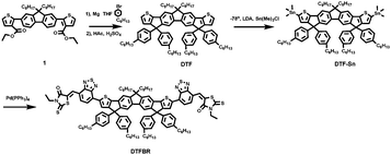
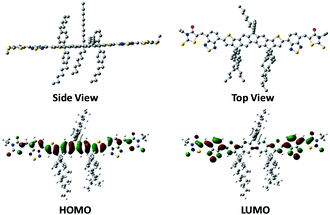
The synthetic process of DTFBR is shown in Scheme 1. The DTF-Sn33 was synthesized according to the previously reported methods. The desired product was synthesized by the classical Stilling coupling reactions. In order to better study the molecular geometries, molecular frontier orbitals and electronic distribution, density functional theory (DFT) calculations were performed at the B3LYP/6-31G(d,p) level of theory. As shown in Fig. 1, DTFBR possesses a nearly planar backbone structure with out-of-plane hexylbenzene and n-octyl. The coplanar backbone configuration of DTFBR is conducive to forming close π–π stacking, which can lead to high carrier mobility. Furthermore, the twisted hexylbenzene and n-octyl restrict large-scale phase separation in the blend film.40 Additionally, according to the wave functions of the geometry optimized structures of DTFBR, we can conclude that the HOMO orbital is mainly delocalized on the fluorene and BT units, and the LUMO is distributed on the BT and terminal rhodamine units. The HOMO and LUMO energy levels calculated from DFT are −3.19 eV and −5.12 eV, respectively.Optical properties
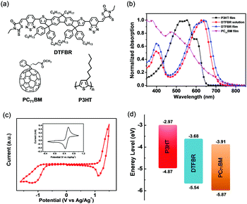
The UV-vis absorption spectra of DTFBR in DCB solution and in the solid state are displayed in Fig. 2b. There are two absorption peaks which can be identified both in the solution and film of DTFBR. The longer wavelength absorption peak stems from the intramolecular charge transfer (ICT) from fluorine fused rings (electron donor core unit) to the rhodamine (electron withdrawing terminal unit), and the shorter wavelength absorption peak originated from localized π–π* transition.42 In solution, DTFBR showed a broad absorption in the wavelength range from 350 nm to 700 nm. The two main absorption peaks were located at 401 nm and 629 nm, respectively, and a red-shift of 14 nm was observed in the solid state. Meanwhile, a shoulder peak located at 595 nm could be found in DTFBR thin film, suggesting an intermolecular π–π* aggregation appeared in the solid state. Additionally, the optical bandgap of DTFBR was calculated to be 1.74 eV from the onset of the absorption.Electrochemical properties
The electrochemical properties of DTFBR were investigated by cyclic voltammetry. The corresponding cyclic voltammogram is shown in Fig. 2c. As shown in Fig. 2c, DTFBR exhibited a reversible oxidation and a quasi-reversible reduction wave. The HOMO and LUMO energy levels could be identified by the equations of HOMO = −(Eox + 4.4) eV and LUMO = −(Ered + 4.4) eV from the onset oxidation and reduction potentials respectively. Using the equations, the HOMO and LUMO energy level values were calculated to be −5.54 eV and −3.68 eV, and the electrochemical band gap was 1.86 eV. Moreover, as shown in Fig. 2d, the energy levels of DTFBR were between those of P3HT (−5.0 eV and −3.1 eV) and PC71BM (−6.1 eV and −3.9 eV). And the offset43 between P3HT and DTFBR as well as DTFBR and PC71BM can ensure efficient exciton separation. The results confirmed our assumption that DTFBR exhibits appropriate energy levels, and can work bifunctionally in OSCs.Carrier mobility properties
The carrier mobility properties of the DTFBR were characterized by a space charge limited current (SCLC) method with a hole-only device structure of ITO/MoO3/DTFBR/MoO3/Al and an electron-only device structure of ITO/Al/DTFBR/Al. The SCLC curves are shown in Fig. S1 (ESI†). The electron and hole mobilities of DTFBR were calculated to be 2.21 × 10⁻⁴ cm2 V−1 s−1 and 8.95 × 10⁻⁵ cm2 V−1 s−1, respectively. The bipolar carrier transport behavior enabled DTFBR to be a promising bifunctional photovoltaic material.Photovoltaic properties
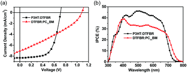
In order to reveal the bifunctional properties of DTFBR in OSCs, the devices with a structure of ITO/PEDOT:PSS/active layer/ZrAcac/Al were fabricated. The device performance was optimized by adjusting the annealing temperature and the donor/acceptor weight ratios, and the related device parameters and current density–voltage (J–V) curves are listed in the ESI† (Tables S2–S5 and Fig. S2–S5). Table 1 summarizes the optimized parameters of the devices with different active layers and the corresponding J–V curves are shown in Fig. 3a. When DTFBR was used as the acceptor with a P3HT donor, a PCE of 3.68% was achieved with a Voc of 0.71 V, a Jsc of 8.15 mA cm−2 and a FF of 0.62. When DTFBR was used as the donor combined with a PC71BM acceptor, a PCE of 2.50% can be obtained, with a Voc of 1.08 V, a Jsc of 6.94 mA cm−2, and a FF of 0.32. In comparison with the photovoltaic parameters of the devices, the DTFBR:PC71BM-based device exhibited a higher Voc than that of the P3HT:DTFBR-based device, which was mainly attributed to the larger energy level offset43 between DTFBR and PC71BM; however, the lower Jsc and FF value led to poor photovoltaic properties for the DTFBR:PC71BM-based device with a PCE of 2.50%. On the basis of the result above, it could be concluded that DTFBR can be used as an acceptor or a donor when combined with different photovoltaic materials in the active layer, which verified that DTFBR exhibits bifunctional properties authentically.Incident photon conversion efficiency (IPCE) spectra of OSCs based on different active layers were measured. As shown in Fig. 3b, the P3HT:DTFBR solar cell showed a narrower photoresponse range (300–750 nm) than that of the DTFBR:PC71BM device (300–800 nm), and this result was consistent with the absorption of the blend film (Fig. S2, ESI†); the extra photoresponse of the DTFBR:PC71BM device in the long wavelength region came from the absorption of PC71BM. For the P3HT:DTFBR device, an IPCE over 40% was achieved from 400 nm to 620 nm, and the maximum value was 47% at approximately 500 nm; whereas, the DTFBR:PC71BM device showed a weaker photoresponse in the absorption range with a maximum IPCE of 38.5% at around 400 nm, thus the P3HT:DTFBR device possessed a higher Jsc. Additionally, the calculated Jsc (8.24 mA cm−2 for P3HT:DTFBR device; 6.92 mA cm−2 for DTFBR:PC71BM device) agreed well with the Jsc obtained from J–V measurement.
Film topography
The film topography of the P3HT:DTFBR and DTFBR:PC71BM blends was measured by AFM and TEM measurements. As shown in Fig. 4, the P3HT:DTFBR blend film showed a rather coarse surface morphology with a high root-mean-square (RMS) roughness of 11.8 nm. However, the DTFBR:PC71BM blend film exhibited a very smooth morphology with a tiny RMS roughness of 0.48 nm. On the other hand, in accordance with the TEM images, we could identify that the P3HT:DTFBR blend film exhibits a strong phase aggregation and a large domain size. However, the DTFBR:PC71BM blend film showed an extreme homogeneous morphology which was indicative of a good compatibility of DTFBR and PC71BM. In addition, the smaller phase separation scale of DTFBR:PC71BM was harmful to efficient charge transport, which could lead to a lower Jsc and FF for the device. This result was consistent with the photovoltaic performance.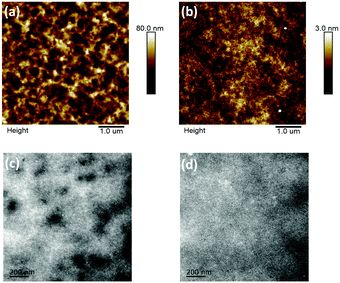 | ||
| Fig. 4 AFM height images (5 × 5 μm) and TEM images (scale bar = 200 nm) of the P3HT:DTFBR (a and c) and DTFBR:PC71BM (b and d) blends. | ||
Conclusions
In conclusion, we designed and synthesized an A–D–A type DTFBR small molecule, in which rhodamine and benzothiazole were employed as the acceptor units and fluorine was employed as the donor unit. DTFBR showed an appropriate energy level, and bipolar charge transport properties, which make DTFBR a bifunctional photovoltaic material. When DTFBR served as the acceptor combined with a P3HT donor, a PCE of 3.68% was obtained. When DTFBR served as the donor with a PC71BM acceptor, a PCE of 2.50% was also achieved. Our work paves the way for developing novel bifunctional organic photovoltaic materials.Experimental
Materials and instruments
All chemical reagents and solvents were purchased from commercial suppliers and used without further purification. Tetrahydrofuran (THF) was freshly distilled from sodium/benzophenoneketyl prior to use. All reactions were performed under a nitrogen atmosphere. 4H-Thieno[2′′,3′′:1′,2′]indeno[5′,6′:5,6]-s-indaceno[1,2-b]thiophene, 4,4,7,7-tetrakis(4-hexylphenyl)-7,12-dihydro-12,12-dioct (DTF-Sn)33 was prepared according to the reported methods. 1H and 13C NMR spectra were recorded on a Bruker AVANCE 600 MHz spectrometer using CDCl3 as the solvent. UV-vis absorption spectra were recorded by UV-vis spectrophotometer (Shimadzu, UV-2700). Atomic force microscopy (AFM) images were measured by using a Dimension Icon AFM (Bruker) in a tapping mode. The electrochemical properties were investigated by cyclic voltammetry, and the cyclic voltammetry curves were measured by a computer-controlled CHI-660E electrochemical workstation with a platinum plate as a working electrode, platinum wire as the counter electrode at a scanning rate of 20 mV s−1 and a Ag/Ag+ electrode as a reference electrode; all the operations were performed in an argon-saturated anhydrous acetonitrile solution of 0.1 M tetrabutylammonium hexafluorophosphate (Bu4NPF6).Device fabrication and characterization
Organic solar cells were fabricated with a conventional structure of ITO/PEDOT:PSS/active layer/ZrAcac/Al. Indium tin oxide (ITO)-coated glass was cleaned by sonication in detergent, deionized water, acetone and isopropyl alcohol successively, then dried overnight in an oven with a temperature of 100 °C. The substrates were treated with oxygen plasma for 30 min before use. After the treatment, a 40 nm-thin layer of PEDOT:PSS (Baytron PVP AI 4083, filltered at 0.45 μm) was spin coated (30 s, 4000 rpm) onto the substrates and annealed at 150 °C for 10 min in air. Then the substrates were transferred into a nitrogen-filled glove box. The active layer was formed by spin-coating the mixed solution in o-dichlorobenzene (o-DCB) onto the top of the PEDOT:PSS layer. For the P3HT:DTFBR active layer, the concentration of the mixed solution was 15 mg ml−1, and the optimized weight ratio and thickness were 1![[thin space (1/6-em)]](https://www.rsc.org/images/entities/char_2009.gif) :
:![[thin space (1/6-em)]](https://www.rsc.org/images/entities/char_2009.gif) 1 and 110 nm respectively, followed by a thermal annealing process at 100 °C for 10 min; for the DTFBR:PC71BM active layer, the concentration of the mixed solution was 10 mg ml−1, and the optimized weight ratio and thickness were 1
1 and 110 nm respectively, followed by a thermal annealing process at 100 °C for 10 min; for the DTFBR:PC71BM active layer, the concentration of the mixed solution was 10 mg ml−1, and the optimized weight ratio and thickness were 1![[thin space (1/6-em)]](https://www.rsc.org/images/entities/char_2009.gif) :
:![[thin space (1/6-em)]](https://www.rsc.org/images/entities/char_2009.gif) 2 and 70 nm respectively. A thin layer of ZrAcac was spin cast atop the active layer and functions as the cathode interfacial layer. Finally, a 100 nm-thick Al electrode was successively deposited on top of the active layers. The characteristic curves of density–voltage (J–V) were measured using a Keithley 2400 Source Measure Unit. The currents were measured under a 100 mW cm−2 simulated 1.5 Global (AM 1.5 G) solar simulator (Enli Technology Co., Ltd, SS-F5-3A). The light intensity was calibrated by a standard Si solar cell (SRC-2020, Enli Technology Co., Ltd). IPCE spectra were measured by using a QEX10 Solar Cell IPCE measurement system (PV measurements, Inc.).
2 and 70 nm respectively. A thin layer of ZrAcac was spin cast atop the active layer and functions as the cathode interfacial layer. Finally, a 100 nm-thick Al electrode was successively deposited on top of the active layers. The characteristic curves of density–voltage (J–V) were measured using a Keithley 2400 Source Measure Unit. The currents were measured under a 100 mW cm−2 simulated 1.5 Global (AM 1.5 G) solar simulator (Enli Technology Co., Ltd, SS-F5-3A). The light intensity was calibrated by a standard Si solar cell (SRC-2020, Enli Technology Co., Ltd). IPCE spectra were measured by using a QEX10 Solar Cell IPCE measurement system (PV measurements, Inc.).
The carrier mobility of DTFBR was measured by the space charge limited current (SCLC) method with a hole-only device structure of ITO/MoO3/DTFBR/MoO3/Al and an electron-only device structure of ITO/Al/DTFBR/Al. The mobilities were calculated by fitting the SCLC curves in accordance with the equation of J = 9ε0εrμV2/8d3, in which J is the current density, ε0 is the permittivity of free space, εr is the relative dielectric constant of the transport medium, μ is the carrier mobility, V is the applied voltage, and d is the thickness of the DTFBR film.
Conflicts of interest
There are no conflicts to declare.Acknowledgements
The authors greatly appreciate the financial support from the National Natural Science Foundation of China (No. 51473009, 21674007, 21734001).Notes and references
- A. J. Heeger, Chem. Soc. Rev., 2010, 39, 2354–2371 RSC.
- S. Nam, J. Seo, S. Woo, W. H. Kim, H. Kim, D. D. Bradley and Y. Kim, Nat. Commun., 2015, 6, 8929 CrossRef PubMed.
- L. Lu, T. Xu, W. Chen, E. S. Landry and L. Yu, Nat. Photonics, 2014, 8, 716 CrossRef.
- J. D. Chen, C. Cui, Y. Q. Li, L. Zhou, Q. D. Ou, C. Li, Y. Li and J. X. Tang, Adv. Mater., 2015, 27, 1035–1041 CrossRef PubMed.
- B. Kan, M. Li, Q. Zhang, F. Liu, X. Wan, Y. Wang, W. Ni, G. Long, X. Yang, H. Feng, Y. Zuo, M. Zhang, F. Huang, Y. Cao, T. P. Russell and Y. Chen, J. Am. Chem. Soc., 2015, 137, 3886–3893 CrossRef PubMed.
- Z. He, B. Xiao, F. Liu, H. Wu, Y. Yang, S. Xiao, C. Wang, T. P. Russell and Y. Cao, Nat. Photonics, 2015, 9, 174 CrossRef.
- J. Zhao, Y. Li, G. Yang, K. Jiang, H. Lin, H. Ade, W. Ma and H. Yan, Nat. Energy, 2016, 1, 15027 CrossRef.
- T. Liu, X. Pan, X. Meng, Y. Liu, D. Wei, W. Ma, L. Huo, X. Sun, T. H. Lee, M. Huang, H. Choi, J. Y. Kim, W. C. Choy and Y. Sun, Adv. Mater., 2017, 29, 1604251 CrossRef PubMed.
- T. Liu, Y. Guo, Y. Yi, L. Huo, X. Xue, X. Sun, H. Fu, W. Xiong, D. Meng, Z. Wang, F. Liu, T. P. Russell and Y. Sun, Adv. Mater., 2016, 28, 10008–10015 CrossRef PubMed.
- Y. He and Y. Li, Phys. Chem. Chem. Phys., 2011, 13, 1970–1983 RSC.
- D. M. Guldi, B. M. Illescas, C. M. Atienza, M. Wielopolski and N. Martin, Chem. Soc. Rev., 2009, 38, 1587–1597 RSC.
- T. Liu and A. Troisi, Adv. Mater., 2013, 25, 1038–1041 CrossRef PubMed.
- A. a. F. Eftaiha, J.-P. Sun, I. G. Hill and G. C. Welch, J. Mater. Chem. A, 2014, 2, 1201–1213 RSC.
- P. Sonar, J. P. Fong Lim and K. L. Chan, Energy Environ. Sci., 2011, 4, 1558–1574 RSC.
- Y. Lin, Y. Li and X. Zhan, Chem. Soc. Rev., 2012, 41, 4245–4272 RSC.
- J. E. Anthony, Chem. Mater., 2011, 23, 583–590 CrossRef.
- X. Guo, A. Facchetti and T. J. Marks, Chem. Rev., 2014, 114, 8943–9021 CrossRef PubMed.
- Y. Liu, C. Mu, K. Jiang, J. Zhao, Y. Li, L. Zhang, Z. Li, J. Y. Lai, H. Hu, T. Ma, R. Hu, D. Yu, X. Huang, B. Z. Tang and H. Yan, Adv. Mater., 2015, 27, 1015–1020 CrossRef PubMed.
- Y. Lin, F. Zhao, Q. He, L. Huo, Y. Wu, T. C. Parker, W. Ma, Y. Sun, C. Wang, D. Zhu, A. J. Heeger, S. R. Marder and X. Zhan, J. Am. Chem. Soc., 2016, 138, 4955–4961 CrossRef PubMed.
- Y. Lin, J. Wang, Z.-G. Zhang, H. Bai, Y. Li, D. Zhu and X. Zhan, Adv. Mater., 2015, 27, 1170–1174 CrossRef PubMed.
- S. Li, L. Ye, W. Zhao, S. Zhang, S. Mukherjee, H. Ade and J. Hou, Adv. Mater., 2016, 28, 9423–9429 CrossRef PubMed.
- W. Li, Y. An, M. M. Wienk and R. A. J. Janssen, J. Mater. Chem. A, 2015, 3, 6756–6760 RSC.
- H. E. Chang and J. Hou, Acta Phys. – Chim. Sin., 2018, 34, 1202–1210 Search PubMed.
- L. Yang, S. Zhang, C. He, J. Zhang, Y. Yang, J. Zhu, Y. Cui, W. Zhao, H. Zhang, Y. Zhang, Z. Wei and J. Hou, Chem. Mater., 2018, 30, 2129–2134 CrossRef.
- H. Bai, Y. Wang, P. Cheng, J. Wang, Y. Wu, J. Hou and X. Zhan, J. Mater. Chem. A, 2015, 3, 1910–1914 RSC.
- Y. Lin, J. Wang, S. Dai, Y. Li, D. Zhu and X. Zhan, Adv. Energy Mater., 2014, 4, 1400420 CrossRef.
- C. Li, Y. Xie, B. Fan, G. Han, Y. Yi and Y. Sun, J. Mater. Chem. C, 2018, 6, 4873–4877 RSC.
- W. Zhao, S. Li, H. Yao, S. Zhang, Y. Zhang, B. Yang and J. Hou, J. Am. Chem. Soc., 2017, 139, 7148–7151 CrossRef PubMed.
- G. Qiu, Z. Jiang, Z. Ni, H. Wang, H. Dong, J. Zhang, X. Zhang, Z. Shu, K. Lu, Y. Zhen, Z. Wei and W. Hu, J. Mater. Chem. C, 2017, 5, 566–572 RSC.
- H. Shi, W. Fu, M. Shi, J. Ling and H. Chen, J. Mater. Chem. A, 2015, 3, 1902–1905 RSC.
- Y. Wang, B. Kan, X. Ke, F. Liu, X. Wan, H. Zhang, C. Li and Y. Chen, Sol. RRL, 2018, 2, 1700179 CrossRef.
- Y. Lin and X. Zhan, Adv. Energy Mater., 2015, 5, 1501063 CrossRef.
- N. Qiu, H. Zhang, X. Wan, C. Li, X. Ke, H. Feng, B. Kan, H. Zhang, Q. Zhang, Y. Lu and Y. Chen, Adv. Mater., 2017, 29, 1604964 CrossRef PubMed.
- K. N. Winzenberg, P. Kemppinen, F. H. Scholes, G. E. Collis, Y. Shu, T. B. Singh, A. Bilic, C. M. Forsyth and S. E. Watkins, Chem. Commun., 2013, 49, 6307–6309 RSC.
- M.-H. Chen, J. Hou, Z. Hong, G. Yang, S. Sista, L.-M. Chen and Y. Yang, Adv. Mater., 2009, 21, 4238–4242 CrossRef.
- M. Svensson, F. Zhang, S. C. Veenstra, W. J. H. Verhees, J. C. Hummelen, J. M. Kroon, O. Inganäs and M. R. Andersson, Adv. Mater., 2003, 15, 988–991 CrossRef.
- M. Li, Y. Liu, W. Ni, F. Liu, H. Feng, Y. Zhang, T. Liu, H. Zhang, X. Wan, B. Kan, Q. Zhang, T. P. Russell and Y. Chen, J. Mater. Chem. A, 2016, 4, 10409–10413 RSC.
- S. Holliday, R. S. Ashraf, C. B. Nielsen, M. Kirkus, J. A. Rohr, C. H. Tan, E. Collado-Fregoso, A. C. Knall, J. R. Durrant, J. Nelson and I. McCulloch, J. Am. Chem. Soc., 2015, 137, 898–904 CrossRef PubMed.
- S. Li, J. Yan, C.-Z. Li, F. Liu, M. Shi, H. Chen and T. P. Russell, J. Mater. Chem. A, 2016, 4, 3777–3783 RSC.
- Y. Wu, H. Bai, Z. Wang, P. Cheng, S. Zhu, Y. Wang, W. Ma and X. Zhan, Energy Environ. Sci., 2015, 8, 3215–3221 RSC.
- S. Holliday, R. S. Ashraf, A. Wadsworth, D. Baran, S. A. Yousaf, C. B. Nielsen, C. H. Tan, S. D. Dimitrov, Z. Shang, N. Gasparini, M. Alamoudi, F. Laquai, C. J. Brabec, A. Salleo, J. R. Durrant and I. McCulloch, Nat. Commun., 2016, 7, 11585 CrossRef PubMed.
- M. Wang, D. Cai, Z. Yin, S. C. Chen, C. F. Du and Q. Zheng, Adv. Mater., 2016, 28, 3359–3365 CrossRef PubMed.
- C. J. Brabec, C. Winder, N. S. Sariciftci, J. C. Hummelen, A. Dhanabalan, P. A. V. Hal and R. A. J. Janssen, Adv. Funct. Mater., 2002, 12, 709–712 CrossRef.
Footnotes |
| † Electronic supplementary information (ESI) available. See DOI: 10.1039/c8qm00223a |
| ‡ These two authors contributed equally to this work. |
| This journal is © the Partner Organisations 2018 |

