Hole-transporting materials based on thiophene-fused arenes from sulfur-mediated thienannulations†
Hsing-An
Lin
ab,
Nobuhiko
Mitoma
 ab,
Lingkui
Meng
bc,
Yasutomo
Segawa
 *ab,
Atsushi
Wakamiya
 *d and
Kenichiro
Itami
 *abce
*abce
aJST, ERATO, Itami Molecular Nanocarbon Project, Nagoya University, Chikusa, Nagoya 464-8602, Japan. E-mail: ysegawa@nagoya-u.jp; wakamiya@scl.kyoto-u.ac.jp; itami@chem.nagoya-u.ac.jp
bGraduate School of Science, Nagoya University, Japan
cIntegrated Research Consortium on Chemical Science, Nagoya University, Japan
dInstitute for Chemical Research, Kyoto University, Uji, Kyoto 611-0011, Japan
eInstitute of Transformative Bio-Molecules (WPI-ITbM), Nagoya University, Japan
First published on 27th November 2017
Abstract
Dithienonaphthalene and dithienochrysene derivatives that bear diarylaminophenyl groups were prepared in two steps from commercially available compounds via a Sonogashira coupling, followed by a simple sulfur-mediated thienannulation. Owing to their relatively narrow HOMO–LUMO gaps, the thus obtained compounds showed bathochromically shifted UV-Vis absorption and fluorescence spectra with higher quantum yields compared to the molecules without the diarylaminophenyl groups. Moreover, the suitable energy levels of their HOMOs and reversible redox properties permit applications for these compounds in hole-transporting layers in perovskite solar cells.
Introduction
Thiophene-fused π-conjugated systems have attracted significant attention in materials science on account of their outstanding charge-transporting properties, which originate from their highly delocalized electronic structures, strong intermolecular π–π interactions, and suitable energy levels of their highest occupied molecular orbitals (HOMOs). Owing to these promising characteristics, a variety of thiophene-fused π-conjugated molecules have been developed and used as semiconductors in organic field-effect transistors (OFETs) and organic light-emitting diodes (OLEDs).1–4 Moreover, thiophene and thiophene-fused molecules that bear triphenylamine moieties have been employed as core structures in the development of donor–π–donor-type hole-transporting materials (HTMs) for perovskite solar cells.5–12Thiophene-annulation reactions (thienannulations) have been widely employed to prepare a variety of thiophene-fused molecules from arenes and polycyclic aromatic hydrocarbons (PAHs). In general, arenes and PAHs with two functional moieties such as halogen, alkynyl, or sulfur-containing groups are necessary to form a fused thiophene ring on the aromatic cores,13–15 even though there are a few other examples.16–20 In any case, conventional thienannulations usually require multiple steps to generate thiophene-fused cores.
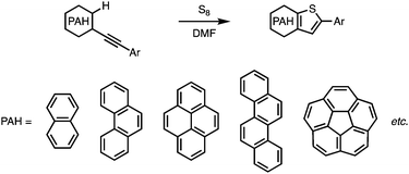
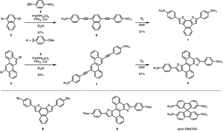
Very recently, we have reported a sulfur-mediated thienannulation of alkynylated PAHs (Fig. 1a).21 This reaction requires merely one arylethynyl group to create a thiophene ring. Moreover, amino groups are tolerated under the applied reaction conditions. We anticipated that this reaction could provide a step-economical route to thiophene-fused PAHs that contain triphenylamine moieties. Herein, we report the synthesis of naphtho[2,1-b:3,4-b′]dithiophene and chryseno[5,6-b:11,12-b′]dithiophene derivatives that bear 4-(di-p-anisylamino)phenyl groups (1 and 2; Scheme 1) via a Sonogashira coupling reaction followed by a thienannulation. Photophysical measurements and DFT calculations revealed the effect of the diarylaminophenyl groups on the HOMO energy levels of the thus obtained molecules. The hole-transporting mobilities of the thiophene-fused PAHs were examined, and the device performance of perovskite solar cells based on 1 and 2 as the hole-transporting layer was evaluated.
Results and discussion
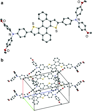
Thiophene-fused PAHs 1 and 2 were synthesized from 1,4-dibromonaphthalene (3) or 6,12-dibromochrysene (4) with N,N-di-p-anisyl-4-ethynylaniline (5) (Scheme 1). A Pd-catalyzed Sonogashira coupling reaction22 of 3 with 5 furnished dialkynylated naphthalene 6 in 87% yield, which was subsequently subjected to sulfur-mediated thienannulation reaction conditions (3.9 equiv. of S8, DMF, 140 °C, 48 h)21 to afford 1 in 37% yield. Similarly, 7, synthesized by a Sonogashira coupling of 4 and 5, was converted into 2 (67% yield). As expected, the diarylaminophenyl groups of 6 and 7 remained unaffected under the thienannulation reaction conditions. In the thienannulation, 7 exhibited higher reactivity, which is consistent with previous findings that chrysene derivatives are more susceptible to such thienannulations than naphthalene derivatives.211 and 2 were characterized by 1H and 13C NMR spectroscopy, as well as by high-resolution MALDI-TOF mass spectrometry measurements. The structure and packing mode of 2 in the solid state was confirmed by a single-crystal X-ray diffraction analysis (Fig. 2). Single crystals of 2 were obtained from a recrystallization in CH2Cl2/EtOH, and contained one molecule of CH2Cl2 per unit cell. In the packing mode of 2 (Fig. 2b), efficient π–π stacking was not observed.The photophysical properties of 1 and 2 were investigated. The UV-Vis absorption and fluorescence spectra of 1 and 2, as well as of reference compounds 8 and 921 are shown in Fig. 3. As summarized in Table 1, 1 and 2 exhibit absorption maxima at 424 and 446 nm, respectively. The absorption spectra of 1 and 2 showed bathochromically shifted absorptions relative to those of 8 and 9, which should be attributed to the π-extension of the core structures and the electron-donating properties of the diarylaminophenyl groups. The effect of the diarylaminophenyl groups on the HOMO levels of 1 and 2 are also supported by DFT calculations (Table 1). The fluorescence maxima of 1 and 2 appeared at 497 and 523 nm, respectively, and 1 and 2 displayed large Stokes shifts of 73 and 77 nm, respectively, presumably because of the polarization in the excited states owing to the donor–π–donor-type structures. In addition, the fluorescence quantum yields of 1 and 2 were higher than those of 8 and 9, respectively. In contrast to the solution state, no fluorescence was observed from 1 and 2 in the solid state.
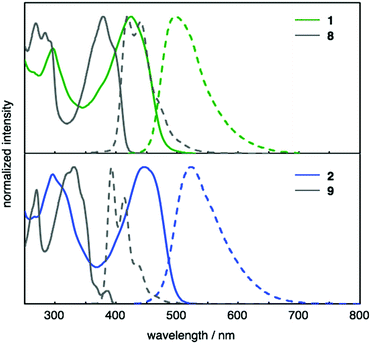 | ||
| Fig. 3 UV-Vis absorption (solid lines) and fluorescence (dashed lines) spectra of CH2Cl2 solutions of 1 (green), 2 (blue), 8 (gray), and 9 (gray). | ||
| λ abs [nm] | λ em [nm] | Φ F | KS-HOMOc [eV] | HOMOe [eV] | |
|---|---|---|---|---|---|
| a Emission maxima upon excitation at 446 nm (1), 380 nm (8), 445 nm (2), and 330 nm (9). b Absolute fluorescence quantum yields determined by a calibrated integrating sphere system (error: ±3%). c Kohn–Sham (KS)-HOMOs calculated at the B3LYP/6-31G(d) level of theory. d For the calculations, n-Bu and n-hex groups were replaced with Me groups. e HOMO levels were estimated from the onset potentials of the first oxidation peaks in the cyclic voltammogram [HOMO = −(Eonset + 5.1 eV)]. | |||||
| 1 | 424 | 497 | 0.55 | −4.42 | −5.14 |
| 8 | 381, 397 | 417, 438 | 0.26 | −5.06d | — |
| 2 | 446 | 523 | 0.22 | −4.43 | −5.00 |
| 9 | 345, 370 | 392, 413 | 0.08 | −4.97d | — |
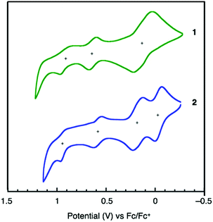
Cyclic voltammetry (CV) measurements were carried out to determine the electrochemical properties and the HOMO energy levels of 1 and 2. As shown in Fig. 4, both 1 and 2 exhibit good electrochemical stability and undergo three- and four-step oxidations, respectively. Considering the higher current of the first peak than those of the second and third peaks of 1, the first oxidation of 1 should be simultaneous two-electron oxidation and 1 exhibits four-electron oxidation similar to 2. The HOMO energy levels of 1 (−5.14 eV) and 2 (−5.00 eV), calculated from the onset of their oxidation potentials relative to Fc/Fc+, are higher than the valence-band level of perovskite (−5.44 eV).23
Furthermore, we employed 1 and 2 to fabricate OFETs in order to measure their hole mobilities (μh). Initially, we fabricated top-contact/bottom-gate OFETs on Si/SiO2 substrates by a drop-cast method using toluene solutions of 1 and 2, followed by evaporative deposition of a gold electrode. The amorphous thin films (see ESI† for detail) of 1 and 2 worked as p-type semiconductors under an inert atmosphere with mobilities (μh) of 8.6 × 10⁻⁴ and 2.5 × 10⁻⁵ cm2 V−1 s−1, respectively, which are higher than those of thiophene derivatives bearing (di-p-anisylamino)phenyl groups.6
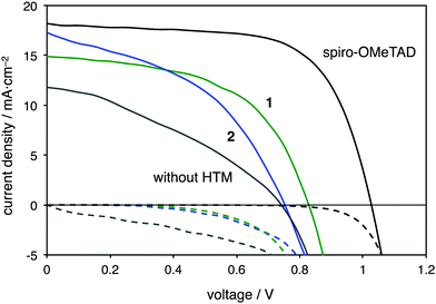
Given their suitable HOMO energy levels and the good hole mobilities, 1 and 2 were applied as hole-transporting layers (HTLs) for the fabrication of perovskite solar cells with an FTO/meso-TiO2/CH3NH3PbI3/HTM/Au configuration.24 In addition, a solar cell with spiro-OMeTAD as the HTM was prepared, together with a cell that did not contain any HTM. Fig. 5 shows the current–density–voltage (J–V) curves of these devices and the photovoltaic performance parameters of the perovskite solar cells are summarized in Table 2. After optimization of the devices, the power conversion efficiency (PCE) of the solar cells increased by incorporating the two additives lithium bis(trifluoromethanesulfonyl)imide (Li-TFSI) and 4-tert-butylpyridine (TBP) into the HTMs.24 The PCEs of devices using 1 (6.7%) and 2 (5.7%) are higher than that of the device that did not contain any HTM (3.1%). The PCE of the control device using spiro-OMeTAD showed a better performance (12.3%) than the devices with thiophene-fused HTMs.
| J sc (mA cm−2) | V oc (V) | FF | PCE (%) | |
|---|---|---|---|---|
| a Composition of the solutions for the deposition of HTLs: HTM (0.060 M), TBP (0.098 M), and Li-TFSI (0.158 M) in chlorobenzene. b HTM (0.015 M), TBP (0.098 M), and Li-TFSI (0.158 M) in chlorobenzene. | ||||
| 1 | 14.9 | 0.83 | 0.54 | 6.7 |
| 2 | 17.3 | 0.75 | 0.44 | 5.7 |
| Spiro-OMeTADa | 18.2 | 1.02 | 0.66 | 12.3 |
| without HTM | 11.4 | 0.74 | 0.35 | 3.1 |
Conclusions
We have synthesized dithienonaphthalene and dithienochrysene derivatives that contain diarylaminophenyl groups (1 and 2) in two steps using a Sonogashira reaction followed by a simple sulfur-mediated thienannulation. 1 and 2 exhibit relatively narrow HOMO–LUMO gaps compared to the corresponding compounds without diarylaminophenyl groups, which resulted in bathochromic shifts in their UV-Vis absorption and fluorescence spectra. Given their reversible electrochemical properties and the suitable HOMO energy levels of 1 and 2, these were used to fabricate OFETs and perovskite solar cells to demonstrate their potential utility as hole-transporting materials. Our concise synthetic route to thiophene-fused π-systems should provide a new strategy to develop organic semiconductors of the donor–π–donor type.Experimental section
General information
Unless otherwise noted, all materials including dry solvents were obtained from common commercial suppliers and used without further purification. All reactions were performed using standard vacuum-line and Schlenk techniques. Work-up and purification procedures were carried out with reagent-grade solvents under air. N,N-Di-p-anisyl-4-ethynylaniline (5)25 was synthesized according to previously reported procedures. Analytical thin-layer chromatography (TLC) was performed using E. Merck silica gel 60 F254 pre-coated plates (0.25 mm). The developed chromatograms were analyzed using a UV lamp (254 nm). Flash column chromatography was performed with E. Merck silica gel 60 (230–400 mesh). High-resolution mass spectra (HRMS) were recorded using a Bruker Daltonics Ultraflex III TOF/TOF (MALDI-TOF-MS). ICP-MS was performed using a Shimadzu ICPM-8500. Nuclear magnetic resonance (NMR) spectra were recorded using a JEOL ECA 600II spectrometer (1H 600 MHz, 13C 150 MHz) with an UltraCool probe. Chemical shifts in the 1H NMR spectra are expressed in parts per million (ppm) relative to CHDCl2 (δ 5.32 ppm) or DMF-d6 (δ 8.00 ppm). Chemical shifts in the 13C NMR spectra are expressed in ppm relative to CD2Cl2 (δ 53.8 ppm) or DMF-d7 (δ 53.98 ppm). Data are reported as follows: chemical shift, multiplicity (s = singlet, d = doublet, t = triplet, dt = doublet of triplets, m = multiplet), coupling constant (Hz), and integration.Synthesis of 6
A 50 mL Schlenk flask containing a magnetic stirring bar was charged with 3 (140 mg, 490 μmol, 1.0 equiv.), Pd(PPh3)2Cl2 (7.0 mg, 1.0 μmol, 2 mol%), PPh3 (5.1 mg, 19 μmol, 4 mol%), and CuI (3.0 mg, 16 μmol, 3 mol%). The flask was filled with argon before Et3N (10.5 mL) and 5 (400 mg, 1.22 mmol, 2.5 equiv.) were added. The mixture was stirred for 24 h at 85 °C. Then, the mixture was cooled to room temperature, and concentrated in vacuo. The residue was subjected to chromatography on silica gel (CHCl3/hexane = 1![[thin space (1/6-em)]](https://www.rsc.org/images/entities/char_2009.gif) :
:![[thin space (1/6-em)]](https://www.rsc.org/images/entities/char_2009.gif) 2) to afford 6 (330 mg, 87% yield) as a yellow solid. 1H NMR (600 MHz, CD2Cl2) δ 8.45 (dd, J = 6.0 Hz, J = 3.0 Hz, 2H), 7.67 (s, 2H), 7.63 (dd, J = 6.0 Hz, J = 3.0 Hz, 2H), 7.42 (d, J = 9.0 Hz, 4H), 7.11 (d, J = 9.0 Hz, 8H), 6.88 (d, J = 9.0 Hz, 4H), 6.86 (d, J = 9.0 Hz, 8H), 3.80 (s, 12H); 13C NMR (150 MHz, CD2Cl2) δ 157.2, 149.8, 145.5, 133.5, 133.0, 130.0, 127.9, 127.6, 127.1, 122.0, 119.2, 115.4, 113.9, 97.4, 86.8, 56.0; HRMS (MALDI-TOF) m/z calcd for C54H42N2O4 [M]+: 782.3139, found: 782.3131.
2) to afford 6 (330 mg, 87% yield) as a yellow solid. 1H NMR (600 MHz, CD2Cl2) δ 8.45 (dd, J = 6.0 Hz, J = 3.0 Hz, 2H), 7.67 (s, 2H), 7.63 (dd, J = 6.0 Hz, J = 3.0 Hz, 2H), 7.42 (d, J = 9.0 Hz, 4H), 7.11 (d, J = 9.0 Hz, 8H), 6.88 (d, J = 9.0 Hz, 4H), 6.86 (d, J = 9.0 Hz, 8H), 3.80 (s, 12H); 13C NMR (150 MHz, CD2Cl2) δ 157.2, 149.8, 145.5, 133.5, 133.0, 130.0, 127.9, 127.6, 127.1, 122.0, 119.2, 115.4, 113.9, 97.4, 86.8, 56.0; HRMS (MALDI-TOF) m/z calcd for C54H42N2O4 [M]+: 782.3139, found: 782.3131.
Synthesis of 7
A 50 mL Schlenk flask containing a magnetic stirring bar was charged with 4 (188 mg, 490 μmol, 1.0 equiv.), Pd(PPh3)2Cl2 (7.0 mg, 1.0 μmol, 2 mol%), PPh3 (5.1 mg, 19 μmol, 4 mol%), and CuI (3.0 mg, 16 μmol, 3 mol%). The flask was filled with argon before Et3N (10.5 mL) and 5 (400 mg, 1.22 mmol, 2.5 equiv.) were added. The mixture was stirred for 24 h at 85 °C. Then, the mixture was cooled to room temperature and concentrated in vacuo. The residue was subjected to chromatography on silica gel (CHCl3/hexane = 2![[thin space (1/6-em)]](https://www.rsc.org/images/entities/char_2009.gif) :
:![[thin space (1/6-em)]](https://www.rsc.org/images/entities/char_2009.gif) 1) to afford 7 (400 mg, 93% yield) as a yellow solid. 1H NMR (600 MHz, CD2Cl2) δ 8.98 (s, 2H), 8.83 (d, J = 8.4 Hz, 2H), 8.62 (d, J = 8.4 Hz, 2H), 7.81–7.74 (m, 4H), 7.51 (d, J = 9.0 Hz, 4H), 7.13 (d, J = 9.0 Hz, 8H), 6.90 (d, J = 9.0 Hz, 4H), 6.89 (d, J = 9.0 Hz, 8H), 3.81 (s, 12H); 13C NMR (150 MHz, CD2Cl2) δ 157.3, 149.9, 140.5, 133.1, 132.1, 130.5, 128.1, 128.0, 127.7, 127.5, 125.8, 123.9, 121.8, 119.3, 115.4, 113.9, 96.6, 87.3, 56.0; HRMS (MALDI-TOF) m/z calcd for C62H46N2O4 [M]+: 882.3452, found: 882.3452.
1) to afford 7 (400 mg, 93% yield) as a yellow solid. 1H NMR (600 MHz, CD2Cl2) δ 8.98 (s, 2H), 8.83 (d, J = 8.4 Hz, 2H), 8.62 (d, J = 8.4 Hz, 2H), 7.81–7.74 (m, 4H), 7.51 (d, J = 9.0 Hz, 4H), 7.13 (d, J = 9.0 Hz, 8H), 6.90 (d, J = 9.0 Hz, 4H), 6.89 (d, J = 9.0 Hz, 8H), 3.81 (s, 12H); 13C NMR (150 MHz, CD2Cl2) δ 157.3, 149.9, 140.5, 133.1, 132.1, 130.5, 128.1, 128.0, 127.7, 127.5, 125.8, 123.9, 121.8, 119.3, 115.4, 113.9, 96.6, 87.3, 56.0; HRMS (MALDI-TOF) m/z calcd for C62H46N2O4 [M]+: 882.3452, found: 882.3452.
Synthesis of 1
A 10 mL Schlenk tube containing a magnetic stirring bar was charged with 6 (312 mg, 399 μmol) and S8 (400 mg, 1.50 mmol, 3.9 equiv.). The tube was filled with argon before DMF (4.0 mL) was added and the mixture was stirred for 48 h at 140 °C. Then, the mixture was cooled to room temperature and concentrated in vacuo. The residue was subjected to chromatography on silica gel (CHCl3/hexane = 1![[thin space (1/6-em)]](https://www.rsc.org/images/entities/char_2009.gif) :
:![[thin space (1/6-em)]](https://www.rsc.org/images/entities/char_2009.gif) 2) to afford 1 (125 mg, 37% yield) as an orange solid. 1H NMR (600 MHz, DMF-d7) δ 8.63 (dd, J = 6.0 Hz, J = 3.0 Hz, 2H), 8.58 (s, 2H), 7.79 (d, J = 9.0 Hz, 4H), 7.67 (dd, J = 6.0 Hz, J = 3.0 Hz, 2H), 7.15 (d, J = 9.0 Hz, 8H), 6.99 (d, J = 9.0 Hz, 8H), 6.91 (d, J = 9.0 Hz, 4H), 3.81 (s, 12H); 13C NMR (150 MHz, DMF-d7) δ 156.8, 149.3, 142,5, 140.3, 135.8, 129.9, 127.8, 127.5, 127.0, 126.3, 125.5, 125.0, 119.4, 118.0, 115.2, 55.3; HRMS (MALDI-TOF) m/z calcd for C54H42N2O4S2 [M]+: 846.2581, found: 846.2576.
2) to afford 1 (125 mg, 37% yield) as an orange solid. 1H NMR (600 MHz, DMF-d7) δ 8.63 (dd, J = 6.0 Hz, J = 3.0 Hz, 2H), 8.58 (s, 2H), 7.79 (d, J = 9.0 Hz, 4H), 7.67 (dd, J = 6.0 Hz, J = 3.0 Hz, 2H), 7.15 (d, J = 9.0 Hz, 8H), 6.99 (d, J = 9.0 Hz, 8H), 6.91 (d, J = 9.0 Hz, 4H), 3.81 (s, 12H); 13C NMR (150 MHz, DMF-d7) δ 156.8, 149.3, 142,5, 140.3, 135.8, 129.9, 127.8, 127.5, 127.0, 126.3, 125.5, 125.0, 119.4, 118.0, 115.2, 55.3; HRMS (MALDI-TOF) m/z calcd for C54H42N2O4S2 [M]+: 846.2581, found: 846.2576.
Synthesis of 2
A 10 mL Schlenk tube containing a magnetic stirring bar was charged with 7 (176 mg, 199 μmol) and S8 (200 mg, 781 μmol, 3.9 equiv.). The tube was filled with argon before DMF (2.0 mL) was added and the mixture was stirred for 48 h at 140 °C. Then, the mixture was cooled to room temperature and concentrated in vacuo. The residue was subjected to chromatography on silica gel (CHCl3/hexane = 2![[thin space (1/6-em)]](https://www.rsc.org/images/entities/char_2009.gif) :
:![[thin space (1/6-em)]](https://www.rsc.org/images/entities/char_2009.gif) 1) to afford 2 (120 mg, 67% yield) as an orange solid. 1H NMR (600 MHz, DMF-d7) δ 9.45 (d, J = 7.8 Hz, 2H), 8.88 (d, J = 7.2 Hz, 2H), 8.75 (s, 2H), 7.93–7.86 (m, 4H), 7.91 (d, J = 9.0 Hz, 4H), 7.18 (d, J = 9.0 Hz, 8H), 7.01 (d, J = 9.0 Hz, 8H), 6.96 (d, J = 9.0 Hz, 4H), 3.83 (s, 12H); 13C NMR (150 MHz, DMF-d7) δ 156.9, 149.5, 144.6, 140.3, 137.4, 133.0, 129.1, 128.6, 127.7, 127.5, 127.2, 126.9, 125.3, 125.0, 124.4, 119.5, 115.2, 55.3; HRMS (MALDI-TOF) m/z calcd for C62H46N2O4S2 [M]+: 946.2894, found: 946.2905.
1) to afford 2 (120 mg, 67% yield) as an orange solid. 1H NMR (600 MHz, DMF-d7) δ 9.45 (d, J = 7.8 Hz, 2H), 8.88 (d, J = 7.2 Hz, 2H), 8.75 (s, 2H), 7.93–7.86 (m, 4H), 7.91 (d, J = 9.0 Hz, 4H), 7.18 (d, J = 9.0 Hz, 8H), 7.01 (d, J = 9.0 Hz, 8H), 6.96 (d, J = 9.0 Hz, 4H), 3.83 (s, 12H); 13C NMR (150 MHz, DMF-d7) δ 156.9, 149.5, 144.6, 140.3, 137.4, 133.0, 129.1, 128.6, 127.7, 127.5, 127.2, 126.9, 125.3, 125.0, 124.4, 119.5, 115.2, 55.3; HRMS (MALDI-TOF) m/z calcd for C62H46N2O4S2 [M]+: 946.2894, found: 946.2905.
Empirical formula: C63H48Cl2N2O4S2; formula weight: 1032.05; triclinic; space group: P![[1 with combining macron]](https://www.rsc.org/images/entities/char_0031_0304.gif) ; a = 10.1597(7) Å; b = 11.6731(8) Å; c = 22.4151(13) Å; α = 96.0864(15)°; β = 91.8662(17)°; γ = 108.699(2)°; V = 2497.6(3) Å3; Z = 2; Dcalc = 1.372 g cm−3; μ = 0.268 mm−1; F(000) = 1076; crystal size: 0.25 × 0.20 × 0.15 mm3; θ range: 3.004°–25.000°; reflections collected: 76
; a = 10.1597(7) Å; b = 11.6731(8) Å; c = 22.4151(13) Å; α = 96.0864(15)°; β = 91.8662(17)°; γ = 108.699(2)°; V = 2497.6(3) Å3; Z = 2; Dcalc = 1.372 g cm−3; μ = 0.268 mm−1; F(000) = 1076; crystal size: 0.25 × 0.20 × 0.15 mm3; θ range: 3.004°–25.000°; reflections collected: 76![[thin space (1/6-em)]](https://www.rsc.org/images/entities/char_2009.gif) 385; independent reflections: 8768; Rint = 0.0300; parameters: 690; GOF: 1.035; R1 = 0.0456, wR2 = 0.1161 (I > 2σ(I)); R1 = 0.0497, wR2 = 0.1197 (for all data).
385; independent reflections: 8768; Rint = 0.0300; parameters: 690; GOF: 1.035; R1 = 0.0456, wR2 = 0.1161 (I > 2σ(I)); R1 = 0.0497, wR2 = 0.1197 (for all data).
Photophysical measurements
Dilute solutions in degassed spectral grade CH2Cl2 in a 1 cm square quartz cell were used for all measurements. UV-Vis absorption spectra were recorded using a Shimadzu UV-3510 spectrometer with a resolution of 0.5 nm. Emission spectra were measured using a F-4500 Hitachi or Shimadzu RF-6000 spectrometer with a resolution of 0.4 nm. Absolute fluorescence quantum yields (ΦF) were determined by a Shimadzu RF-6000 using a calibrated integrating sphere system (207-21460-41).OFET fabrication
OFETs were fabricated in a top-contact/bottom-gate configuration on a heavily doped n+-Si (100) wafer with a 300 nm-thick thermal silicon oxide (SiO2) dielectric layer. Prior to use, the Si/SiO2 substrates were cleaned by consecutive sonication in acetone and 2-propanol, followed by drying. Thin films of 1 and 2 were grown on Si/SiO2 substrates using the drop-cast method. For that purpose, saturated toluene solutions of 1 or 2 were used at room temperature under a vapor of toluene. Subsequently, gold films (∼200 nm) were deposited through a shadow mask as drain and source electrodes. The transfer characteristics of the devices were measured at room temperature under a nitrogen atmosphere using a Keithley 4200-SCS. The field-effect hole mobility (μh) was calculated in the saturation regime (VDS = −60 V) of the IDS using the following equation: IDS = (WCi/2L)μh(VGS − Vth)2, where W and L are the width and length of the drain–source channel, respectively, Ci is the capacitance of the SiO2 insulator, and VGS and Vth are the gate and threshold voltages, respectively.Perovskite solar cells24
Theoretical study
The Gaussian 09 program29 running on a SGI Altix4700 system was used for optimizations at the B3LYP/6-31G(d) level of theory.30 All structures were optimized without any symmetry assumptions. Unless otherwise noted, zero-point energy, enthalpy, and Gibbs free energy values at 298.15 K and 1 atm were estimated from the gas-phase studies. Harmonic vibration frequency calculations were performed at the same level to verify that all stationary points exhibit no imaginary frequency and are hence local minima.Conflicts of interest
There are no conflicts to declare.Acknowledgements
This work was supported by the JST ERATO program (JPMJER1302 to K. I.), the MEXT Funding Program for KAKENHI (JP16K05771 to Y. S. and JP26288093 to A. W.), and a grant-in-aid for Scientific Research on Innovative Areas “π-Figuration” (JP17H05149) from JSPS. Calculations were performed using the resources of the Research Center for Computational Science, Okazaki, Japan. ITbM is supported by the World Premier International Research Center (WPI) Initiative, Japan.Notes and references
- J. E. Anthony, Angew. Chem., Int. Ed., 2008, 47, 452 CrossRef CAS PubMed.
- W. Jiang, Y. Li and Z. Wang, Chem. Soc. Rev., 2013, 42, 6113 RSC.
- S. Allard, M. Forster, B. Souharce, H. Thiem and U. Scherf, Angew. Chem., Int. Ed., 2008, 47, 4070 CrossRef CAS PubMed.
- S. Shinamura, I. Osaka, E. Miyazaki, A. Nakao, M. Yamagishi, J. Takeya and K. Takimiya, J. Am. Chem. Soc., 2011, 133, 5024 CrossRef CAS PubMed.
- A. Molina-Ontoria, I. Zimmermann, I. Garcia-Benito, P. Gratia, C. Roldán-Carmona, S. Aghazada, M. Graetzel, M. K. Nazeeruddin and N. Martín, Angew. Chem., Int. Ed., 2016, 55, 6270 CrossRef CAS PubMed.
- S. Paek, I. Zimmermann, P. Gao, P. Gratia, K. Rakstys, G. Grancini, M. K. Nazeeruddin, M. A. Rub, S. A. Kosa, K. A. Alamry and A. M. Asiri, Chem. Sci., 2016, 7, 6068 RSC.
- X. Liu, F. Kong, F. Guo, T. Cheng, W. Chen, T. Yu, J. Chen, Z. A. Tan and S. Dai, Dyes Pigm., 2017, 139, 129 CrossRef CAS.
- X. Liu, F. Kong, Z. A. Tan, T. Cheng, W. Chen, T. Yu, F. Guo, J. Chen, J. Yao and S. Dai, RSC Adv., 2016, 6, 87454 RSC.
- I. Zimmermann, J. Urieta-Mora, P. Gratia, J. Aragó, G. Grancini, A. Molina-Ontoria, E. Ortí, N. Martín and M. K. Nazeeruddin, Adv. Energy Mater., 2017, 7, 1601674 CrossRef.
- H. Li, K. Fu, P. P. Boix, L. H. Wong, A. Hagfeldt, M. Grätzel, S. G. Mhaisalkar and A. C. Grimsdale, ChemSusChem, 2014, 7, 3420 CrossRef CAS PubMed.
- S. Ma, H. Zhang, N. Zhao, Y. Cheng, M. Wang, Y. Shen and G. Tu, J. Mater. Chem. A, 2015, 3, 12139 CAS.
- T. Krishnamoorthy, F. Kunwu, P. P. Boix, H. Li, T. M. Koh, W. L. Leong, S. Powar, A. Grimsdale, M. Grätzel, N. Mathews and S. G. Mhaisalkar, J. Mater. Chem. A, 2014, 2, 6305 CAS.
- M. Nakano and K. Takimiya, Chem. Mater., 2017, 29, 256 CrossRef CAS.
- T. Mori, T. Nishimura, T. Yamamoto, I. Doi, E. Miyazaki, I. Osaka and K. Takimiya, J. Am. Chem. Soc., 2013, 135, 13900 CrossRef CAS PubMed.
- T. Y. Zhang, J. O'Toole and C. S. Proctor, Sulfur Rep., 1999, 22, 1 CrossRef CAS.
- A. J. Eberhart, H. Shrives, Y. Zhang, A. Carrer, A. V. S. Parry, D. J. Tate, M. L. Turner and D. J. Procter, Chem. Sci., 2016, 7, 1281 RSC.
- Y. Fukutomi, M. Nakano, J.-Y. Hu, I. Osaka and K. Takimiya, J. Am. Chem. Soc., 2013, 135, 11445 CrossRef CAS PubMed.
- D. S. Baranov, B. Gold, S. F. Vasilevsky and I. V. Alabugin, J. Org. Chem., 2013, 78, 2074 CrossRef CAS PubMed.
- J. C. Hanekamp, P. A. A. Klusener and L. Brandsma, Synth. Commun., 1989, 19, 2691 CrossRef CAS.
- M. Iwao, M. L. Lee and R. N. Castle, J. Heterocycl. Chem., 1980, 17, 1259 CrossRef CAS.
- L. Meng, T. Fujikawa, M. Kuwayama, Y. Segawa and K. Itami, J. Am. Chem. Soc., 2016, 138, 10351 CrossRef CAS PubMed.
- K. Sonogashira, J. Organomet. Chem., 2002, 653, 46 CrossRef CAS.
- A. Kojima, K. Teshima, Y. Shirai and T. Miyasaka, J. Am. Chem. Soc., 2009, 131, 6050 CrossRef CAS PubMed.
- H. Nishimura, N. Ishida, A. Shimazaki, A. Wakamiya, A. Saeki, L. T. Scott and Y. Murata, J. Am. Chem. Soc., 2015, 137, 15656 CrossRef CAS PubMed.
- J.-H. Lin, A. Elangovan and T.-I. Ho, J. Org. Chem., 2005, 70, 7397 CrossRef CAS PubMed.
- A. Altomare, M. C. Burla, M. Camalli, G. L. Cascarano, C. Giacovazzo, A. Guagliardi, A. G. G. Moliterni, G. Polidori and R. Spagna, J. Appl. Crystallogr., 1999, 32, 115 CrossRef CAS.
- G. M. Sheldrick, Acta Crystallogr., Sect. A: Found. Crystallogr., 2008, 64, 112 CrossRef CAS PubMed.
- (a) K. Wakita and X. G. Yadokari, Software for Crystal Structure Analyses, 2001 Search PubMed; (b) C. Kabuto, S. Akine, T. Nemoto and E. Kwon, J. Crystallogr. Soc. Jpn., 2009, 51, 218 CrossRef.
- M. J. Frisch, G. W. Trucks, H. B. Schlegel, G. E. Scuseria, M. A. Robb, J. R. Cheeseman, G. Scalmani, V. Barone, B. Mennucci, G. A. Petersson, H. Nakatsuji, M. Caricato, X. Li, H. P. Hratchian, A. F. Izmaylov, J. Bloino, G. Zheng, J. L. Sonnenberg, M. Hada, M. Ehara, K. Toyota, R. Fukuda, J. Hasegawa, M. Ishida, T. Nakajima, Y. Honda, O. Kitao, H. Nakai, T. Vreven, J. A. Montgomery, Jr., J. E. Peralta, F. Ogliaro, M. Bearpark, J. J. Heyd, E. Brothers, K. N. Kudin, V. N. Staroverov, R. Kobayashi, J. Normand, K. Raghavachari, A. Rendell, J. C. Burant, S. S. Iyengar, J. Tomasi, M. Cossi, N. Rega, J. M. Millam, M. Klene, J. E. Knox, J. B. Cross, V. Bakken, C. Adamo, J. Jaramillo, R. Gomperts, R. E. Stratmann, O. Yazyev, A. J. Austin, R. Cammi, C. Pomelli, J. W. Ochterski, R. L. Martin, K. Morokuma, V. G. Zakrzewski, G. A. Voth, P. Salvador, J. J. Dannenberg, S. Dapprich, A. D. Daniels, O. Farkas, J. B. Foresman, J. V. Ortiz, J. Cioslowski and D. J. Fox, Gaussian 09, Revision D.01, Gaussian, Inc., Wallingford CT, 2013 Search PubMed.
- (a) A. D. Becke, J. Chem. Phys., 1993, 98, 5648 CrossRef CAS; (b) C. Lee, W. Yang and R. G. Parr, Phys. Rev. B: Condens. Matter Mater. Phys., 1988, 37, 785 CrossRef CAS.
Footnote |
| † Electronic supplementary information (ESI) available: Computational studies, and spectral data for all compounds. CCDC 1562381 (2). For ESI and crystallographic data in CIF or other electronic format see DOI: 10.1039/c7qm00473g |
| This journal is © the Partner Organisations 2018 |

