Nitrogen-rich sandwich-like carbon nanosheets as anodes with superior lithium storage properties†
Hailiang
Chu
 ,
Chunfeng
Shao
,
Shujun
Qiu
,
Chunfeng
Shao
,
Shujun
Qiu
 *,
Yongjin
Zou
 ,
Cuili
Xiang
,
Fen
Xu
and
Lixian
Sun
*
,
Cuili
Xiang
,
Fen
Xu
and
Lixian
Sun
*
Guangxi Key Laboratory of Information Materials, Guangxi Collaborative Innovation Center of Structure and Property for New Energy and Materials and School of Materials Science and Engineering, Guilin University of Electronic Technology, Guilin 541004, PR China. E-mail: qiushujun@guet.edu.cn; sunlx@guet.edu.cn
First published on 13th November 2017
Abstract
Carbon materials such as graphite have been used as anode material for Li-ion batteries (LIBs). However, the energy stored in carbon materials is greatly dependent on their structural characteristics. Herein, nitrogen-rich sandwich-like carbon nanosheets (NSCN) have been prepared through a facile hydrothermal carbonization (HTC) method followed by pyrolysis. The nitrogen-rich sandwich-like carbon nanosheets synthesized at 600 °C (NSCN-600) have a higher specific surface area of 1112 m2 g−1 and a total nitrogen content of 11.4 wt% (therein 9.30 wt% for both pyridinic-N and pyrrolic-N), giving rise to high discharge capacity (910 mA h g−1 at 100 mA g−1 after 50 cycles) and remarkable rate capability (719 mA h g−1 at 500 mA g−1 after 200 cycles and 390 mA h g−1 at 2000 mA g−1). Such desirable electrochemical properties could be attributed to the unique sandwich-like nanostructures consisting of a number of amorphous carbon nanoparticles closely covered with carbon sheet layers. Such a simple preparation method could provide a strategy for rational engineering of nanostructured nitrogen-rich carbonaceous materials for high-performance LIBs.
Introduction
As one of the most promising devices for high-efficiency electrochemical energy storage, lithium-ion batteries (LIBs) have shown great potential in practical applications for the development of portable electronic devices, electrical vehicles and electrical grids.1–6 A lot of advanced composite materials including metal oxides7,8 and nanosized semiconductors9–11 have shown great potential in the application of LIBs. At present, carbon materials are still the dominant anode materials for commercial LIBs due to their high electrical conductivity, excellent electrochemical properties and low cost.12–14 However, the theoretical specific capacity of traditional graphite is limited to 372 mA h g−1 corresponding to LixC6 (x < 1). Consequently, a variety of carbonaceous materials including hard (non-graphitizable) carbon and soft (graphitizable) carbon have been achieved with a reversible discharge capacity in the range of 500–900 mA h g−1 due to the dual effect of Li+ adsorption onto the carbon framework and Li+ filling of interspersed nanopores.15To further improve the electrochemical properties of new-generation LIBs, carbonaceous materials with unique nanostructures should be designed to show the following characteristics: (i) high porosity for reducing diffusion distance and enhancing charge transport of Li+, thereby giving rise to superior rate capability,16–18 (ii) large specific surface area with plentiful active sites for facilitating lithium storage,19,20 (iii) subtle morphology for promoting rapid charge transfer and long cycling life,15,17,21,22 and (iv) heteroatom doping for improving the electronic conductivity and introducing some available active sites by manipulating electronic properties.23–26 To achieve these features, many efforts have been made to synthesise some new carbonaceous materials with various microstructures, such as echinus-like carbon capsules,17 hollow carbon spheres,27 carbon nanofibers,28 N-rich porous carbon derived from biomass15,29,30 and carbon nanobeads.31 Recently, it has been found that N-doped porous carbon showed excellent lithium storage capability and rate performance.15 However, it still remains a great challenge to synthesize a carbonaceous material with both a large surface area and well-controlled hierarchical architecture through a simple preparation process. A few carbonaceous materials have all the aforementioned features because despite using a complicated and high-cost process, most of them exhibit limited active sites and poor structural stability.15,32
As an eco-friendly and cost-effective route, hydrothermal carbonization (HTC) has attracted much attention due to its mild conditions (i.e., 180 °C and pure water solution) with self-generated pressure.29,33–35 Compared with the template method, HTC is a scalable synthesis route for the production of porous carbon. It can effectively transform biomass-derived precursors (such as cellulose,36 saccharides,37–39 lignocellulosic derivatives40 and tannins38,41) into functional carbon-based materials.42 Furthermore, this approach can easily control the balance between porosity, conductivity and functionality of the final products,43 providing a better adaptability for the desirable application.44 The in situ homogeneous doping is an effective process for incorporating nitrogen into carbon hosts using nitrogen-containing precursors such as N-vinyl-2-pyrrolidone (NVP),45 pyrrole,46 melamine,17,47–49 imidazole,14 dopamine hydrochloride,9 urea,50 and NH4Cl.51 Through the introduction of more available active sites, N-doping has been proven to significantly enhance surface polarity and increase both electrochemical reactivity and electronic conductivity of the carbon matrix, thus resulting in superior performance in energy storage applications.10,26,52 Besides nitrogen, oxygen is another promising dopant and the introduction of the dopant may bring a positive influence on the carbon materials, which could afford extra capacity through the transformation of carboxide and enolate,53 and meanwhile improve the conductivity of the carbon materials.54
In this study, we propose a facile HTC approach to synthesize nitrogen-rich sandwich-like carbon nanosheets (NSCN) using low-cost industrial materials such as glucose and guanine. Through an in situ synthesis approach, nitrogen-doping carbon spheres (NCS) can be prepared and then KOH activation during carbonization can be carried out for preparing sandwich-like carbon nanosheets with high-level nitrogen doping, large specific surface area, and satisfactory porosity. Benefiting from both the unique nanostructure and enhanced excellent conductivity, the as-prepared NSCN as a promising anode material for LIBs exhibits excellent lithium storage properties.
Experimental
Synthesis of NSCN
The preparation of NSCN involves a simple procedure as described below. Glucose (2.0 g) and guanine (1.0 g) were dissolved in 30 mL deionized water and stirred for 0.5 h. Subsequently, the mixture was poured into a Teflon-lined autoclave and hydrothermally treated at 180 °C for 6 h. The solid sample was filtered from the solution and thoroughly washed using ethyl alcohol and deionized water, and then dried at 80 °C for 12 h. For improving the conductivity and porosity, the obtained brown product was directly mixed with KOH at a mass ratio of 1![[thin space (1/6-em)]](https://www.rsc.org/images/entities/char_2009.gif) :
:![[thin space (1/6-em)]](https://www.rsc.org/images/entities/char_2009.gif) 1 in an agate mortar. After homogeneous mixing, the sample was heated at different temperatures of 600, 700, and 800 °C, respectively for 2 h in a tube furnace under a N2 atmosphere at a ramping rate of 3 °C min−1. The resulting sample was treated with 1 M HCl solution and then washed with deionized water until the pH of the washing liquid is about 7.0. Finally, the samples were heated overnight at 100 °C. According to the different treating temperatures, the final products were named NSCN-600, NSCN-700, and NSCN-800, respectively. For comparison, the porous carbon prepared at 600 °C without using guanine is denoted as PC-600.
1 in an agate mortar. After homogeneous mixing, the sample was heated at different temperatures of 600, 700, and 800 °C, respectively for 2 h in a tube furnace under a N2 atmosphere at a ramping rate of 3 °C min−1. The resulting sample was treated with 1 M HCl solution and then washed with deionized water until the pH of the washing liquid is about 7.0. Finally, the samples were heated overnight at 100 °C. According to the different treating temperatures, the final products were named NSCN-600, NSCN-700, and NSCN-800, respectively. For comparison, the porous carbon prepared at 600 °C without using guanine is denoted as PC-600.
Materials characterization
Thermogravimetric analysis (TGA) and differential scanning calorimeter (DSC) were carried out from room temperature to 900 °C under nitrogen on a thermal analyzer (SDT-Q600, TA, USA). X-ray diffraction (XRD) patterns of samples were obtained by using a Bruker D8 Advance diffractometer (German) with Cu Kα radiation at a voltage of 40 kV and a current of 40 mA. The morphology of NSCN was characterized by scanning electron microscopy (SEM, JSM-6360LV, JEOL Ltd, Japan) and transmission electron microscopy (TEM, Hitachi JEM-1200EX, JEOL Ltd, Japan) and the corresponding elemental mapping of NSCN was obtained by using an energy dispersive spectrometer (EDS). The pore texture of samples was determined by nitrogen adsorption/desorption isotherms at 77 K (Autosorb iQ2, Quantachrome Instruments, USA). Before measurement, the samples were degassed at 80 °C for 2 h and then 150 °C for 10 h. The specific surface area (SSA) was evaluated using the conventional Brunauer–Emmett–Teller (BET) equation, with the adsorption branch at a relative pressure ranging from 0.05 to 0.3. And the nonlocal density functional theory (NLDFT) was used to analyze the pore size distribution (PSD) of the samples. The total pore volume (Vtotal) was acquired using the adsorbed branch at a relative pressure of 0.99. The volume and specific surface area of the micropore were calculated from the t-plot method in the relative pressure range of 0.2–0.5. Raman spectra were collected using a LabRAM HR Evolution spectrometer (Horiba JY, France). The conductivity of NSCN is measured by using a four-point probe resistivity measurement system. Elemental analysis (EA) was conducted using a Vario-EL Cube (Elementar) elemental analyzer. In order to characterize chemical composition and surface functionalities of NSCN, X-ray photoelectron spectroscopy (XPS, Thermo Scientific Escalab 250Xi, USA) was performed.Electrochemical measurements
Electrochemical characterization was carried out using 2025-type coin cells with the lithium metal as counter and reference electrodes. The slurry was obtained by blending 80% active material, 10% acetylene black and 10% polyvinylidene fluoride (PVDF) binder and then coated on copper foil. After pressing and punching, the working electrodes of 12 mm diameter were fabricated and assembled into coin-type cells in an argon-filled glovebox. The galvanostatic charge–discharge (GCD) cycles were collected on a battery testing system (LAND CT2001A) within a voltage range of 0.01–3.0 V (vs. Li/Li+) at various current densities. Cyclic voltammetry (CV) and electrochemical impedance spectroscopy (EIS) measurements were carried out on a CHI660D electrochemical workstation. CV was conducted at a scan rate of 0.1 mV s−1 in a potential range of 0.01–3.0 V and EIS was performed over the frequency range of 100 kHz–10 mHz.Results and discussion
Materials synthesis and microstructure
Taking into consideration high nitrogen content and abundant amidogen groups, guanine was employed as a dopant and glucose as a carbon source for the polymerization of nitrogen-doping carbon spheres (NCS) to implement the following synthesis of NSCN through KOH activation. The synthesizing procedure is illustrated in Fig. 1. During the activation process, NCS were further carbonized. At the same time, a part of the nitrogen-containing species decomposed gradually due to its instability at high temperature and then transformed into abundant pyridinic-N and pyrrolic-N. The nanostructure of NSCN is constructed by two ultrathin carbon nanosheets interconnected with nanoparticles. This unique sandwich-like nanosheet structure combined with different types of nitrogen species in NSCN could facilitate fast electron transport and mass transport at the electrode/electrolyte interfaces.55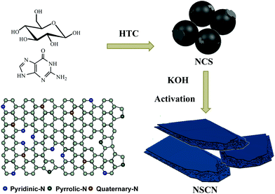 | ||
| Fig. 1 Schematic illustration of the synthesis route toward NSCN through HTC and the subsequent activation process, and the scheme of different types of nitrogen in carbon nanosheets. | ||
TG-DSC was employed to evaluate the activation behavior of NCS. As shown in Fig. 2a, the evident mass loss involves the dehydration reaction of KOH56,57 and the decomposition of NCS with the emission of gaseous products from room temperature to 350 °C. A pronounced weight loss is observed in the activation process of NCS when the temperature is over 350 °C, suggesting the rapid pyrolysis of abundant nitrogen- and oxygen-containing functional groups, which is supported from the observation of the decomposition of guanine (Fig. 2a). The carbon frameworks with good thermal conductivity give rise to the decomposition of guanine ahead of time for NCS, as observed in DSC curves (Fig. 2b). At a temperature of about 600 °C, there is a weight loss of about 59%, indicating that abundant N and O groups can be effectively retained after the pyrolysis process. At this temperature, the nitrogen content is determined to be 11.4 wt% (Table 1). When the temperature is increased to 700 °C and 800 °C, the nitrogen content is decreased to 10.4 wt% and 8.17 wt%, respectively. Meanwhile, the oxygen content also declines with pyrolysis temperature (Table 1). Finally, there is a solid residue of approximately 1 wt% remaining upon heating to 1100 °C.
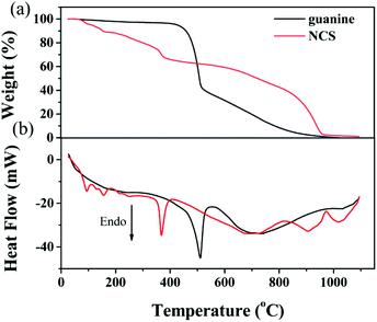 | ||
| Fig. 2 (a) TG and (b) DSC for the activation of NCS. For comparison, TG and DCS of guanine are also included. | ||
| Sample | BET SSA (m2 g−1) | Total pore volume (cm3 g−1) | Pore width (nm) |
I
D/IG![[thin space (1/6-em)]](https://www.rsc.org/images/entities/char_2009.gif) b b |
N (wt%) | O (wt%) | |||
|---|---|---|---|---|---|---|---|---|---|
| Total | Micro | Meso | Ratioa | ||||||
| a The ratio of micropore to mesopore on the SSA. b The intensity ratio of D band to G band. | |||||||||
| PC-600 | 820 | 772 | 47 | 16.42 | 0.47 | 2.29 | 0.65 | — | 14.1 |
| NSCN-600 | 1112 | 893 | 219 | 4.08 | 0.89 | 3.21 | 1.36 | 11.4 | 28.1 |
| NSCN-700 | 1171 | 1082 | 89 | 12.16 | 0.71 | 2.43 | 1.10 | 10.4 | 25.9 |
| NSCN-800 | 1398 | 723 | 675 | 1.07 | 1.39 | 3.91 | 1.01 | 8.17 | 20.8 |
HTC of glucose using guanine as an additive produces rough-surfaced NCS with a particle size of about 5 μm (Fig. 3a). After KOH was added into the carbonation process, a sandwich-like flake with a thickness between a few hundreds of nanometers and a few microns is achieved for NSCN-600 (Fig. 3b). Typically, this sandwich-like structure is made up of two smooth sheets connected by many nanoparticles. With the increase of pyrolysis temperature, NSCN-700 and NSCN-800 exhibit a similar sandwich-like structure (Fig. S1, ESI†). In order to shed light on the influence of guanine, a control experiment was performed for HTC of glucose without any additive, which results in the formation of carbonaceous spheres (CS) with a diameter ranging from 100 to 200 nm (Fig. S2a, ESI†). After KOH activation at 600 °C, PC-600 gives a uniform porous structure (Fig. S2b, ESI†). For the case of NSCN-600, abundant microspores and continuous integrated sheets with plenty of defects are observed from the TEM image (Fig. 3c and its inset). The interface between the double-layer flake structure can generate a large number of defects that may be active sites applicable for lithium ion storage.55 What is more, carbon, nitrogen, and oxygen elements are homogeneously distributed in NSCN-600 sheets (Fig. 3d).
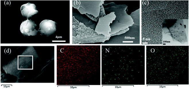 | ||
| Fig. 3 SEM images of (a) NCS and (b) NSCN-600. (c) Typical TEM image and (d) elemental mappings of NSCN-600. | ||
N2 adsorption/desorption isotherms (77 K) are further employed to characterize the porous structure of NSCN. The relevant pore structure parameters derived from the analysis of isotherms are shown in Table 1. As shown in Fig. 4a, PC-600 exhibits a type-I sorption isotherm and has a narrow pore width (Fig. 4b) and a relatively low specific surface area of 820 m2 g−1, indicating the existence of a superabundant micropore (Table 1). By contrast, all NSCN samples show a typical type-I adsorption/desorption isotherm with pronounced H3 hysteresis loops, which indicate the existence of some portion of mesopores in the sandwich-like structure.14 These mesopores may originate from the etch of the carbon framework through the KOH activation.46 In addition, the adsorption at the relative low pressure displays high microporosity, which hence gives rise to larger SSA. The BET surface area is determined to be 1112, 1171, and 1398 m2 g−1 for NSCN-600, NSCN-700, and NSCN-800, respectively (Table 1). Furthermore, abundant micropores and moderate mesopores of the NSCN samples are observed in Fig. 4b. In consideration of the pore volume and the ratio of micropore to mesopore on SSA shown in Table 1, NSCN-600 exhibits a more appropriate pore volume (0.89 cm3 g−1) and ratio (4.08), which could contribute to the enhancement of the rate capability of LIBs because abundant micropores are expected to supply storage sites for Li+ insertion/extraction and moderate mesopores can facilitate charge transfer during charge/discharge cycles. In addition, the electronic conductivity of the powder samples, as measured by using a four-point probe technique, is 3.8 S cm−1 for NSCN-600, 4.1 S cm−1 for NSCN-700 and 4.3 S cm−1 for NSCN-800, which was comparable to commercial activated carbon (Norit AC, 0.3 S cm−1; Supra 50, 4.3 S cm−1).58
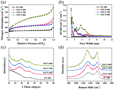 | ||
| Fig. 4 (a) Nitrogen sorption isotherms, (b) corresponding calculated PSD curves, (c) XRD patterns, and (d) Raman spectra of NSCN. | ||
Fig. 4c represents the XRD patterns of NSCN samples. Two broad diffraction peaks can be indexed to (002) and (100) planes of graphite, implying a typical amorphous carbon composed of thin graphitic crystal domains with random distribution.59,60 In addition, the increase of pyrolysis temperature results in a further augmentation of the graphitization degree, which is confirmed by the Raman results (Fig. 4d). Two evident peaks centered at around 1340 and 1586 cm−1 are assigned to the defects or the disordered carbon structure (D band) and the vibration of sp2-hybridized carbon atoms in the graphitic layer (G band),61 respectively. The intensity ratio between D and G bands (ID/IG) is usually used to be an indicator of the disordered degree of carbon materials.55 This ratio of NSCN-600 is much higher than those of NSCN-700 and NSCN-800 (Table 1), illustrating more graphitization obtained at higher treating temperatures62 and also suggesting a more disordered structure with defects of NSCN-600 derived from different contents of different nitrogen types (see below).
To further investigate the chemical compositions and nitrogen bonding configurations of NSCN samples, XPS measurements were conducted. As can be seen from survey spectra in Fig. 5a, all samples reveal predominant peaks of carbon at about 285 eV, oxygen at about 533 eV and nitrogen at about 400 eV without any other impurities.17,63 Fig. S3 (ESI†) shows the high-resolution C 1s spectra of the NSCN samples with the main C–C peak (diamond and graphite type) at 284.8 eV, ethereal carbon (C–O/C–N) peaks at 285.6 eV and carbonyl carbon (C![[double bond, length as m-dash]](https://www.rsc.org/images/entities/char_e001.gif) O/C
O/C![[double bond, length as m-dash]](https://www.rsc.org/images/entities/char_e001.gif) N) peaks centered at 288.2 eV.62,64 These surface functional groups are generally known to enhance the capacity of the engineered carbon materials for the fast reaction with lithium.15 In the case of nitrogen in Fig. 5b–d, it can be assigned to pyridinic N (N-6, 398.6 eV), pyrrolic-N (N-5, 400.1 eV) and quaternary-N (N-Q, 401.0 eV).48 The ratio of different types of N configurations (Fig. 1) varies, which is attributed to the restoration of the conjugated structure during the activation process at different temperatures. Doping nitrogen in carbon frameworks (especially for N-6 and N-5) could generate more active sites and nanopores to facilitate the transport and storage of Li+.65 As clearly shown in Table 1, the nitrogen content of the NSCN samples is dependent on the pyrolysis temperature, i.e., the total amount of N-6 and N-5 decreases with the increase of activation temperature. Hence, NSCN-600 has a total amount of 9.30 wt% including N-5 and N-6, which is higher than those of NSCN-700 (7.53 wt%) and NSCN-800 (4.85 wt%). Therefore, guanine is supposed to be a very promising nitrogen source for the preparation of nitrogen-doping carbon materials.
N) peaks centered at 288.2 eV.62,64 These surface functional groups are generally known to enhance the capacity of the engineered carbon materials for the fast reaction with lithium.15 In the case of nitrogen in Fig. 5b–d, it can be assigned to pyridinic N (N-6, 398.6 eV), pyrrolic-N (N-5, 400.1 eV) and quaternary-N (N-Q, 401.0 eV).48 The ratio of different types of N configurations (Fig. 1) varies, which is attributed to the restoration of the conjugated structure during the activation process at different temperatures. Doping nitrogen in carbon frameworks (especially for N-6 and N-5) could generate more active sites and nanopores to facilitate the transport and storage of Li+.65 As clearly shown in Table 1, the nitrogen content of the NSCN samples is dependent on the pyrolysis temperature, i.e., the total amount of N-6 and N-5 decreases with the increase of activation temperature. Hence, NSCN-600 has a total amount of 9.30 wt% including N-5 and N-6, which is higher than those of NSCN-700 (7.53 wt%) and NSCN-800 (4.85 wt%). Therefore, guanine is supposed to be a very promising nitrogen source for the preparation of nitrogen-doping carbon materials.
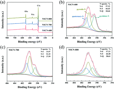 | ||
| Fig. 5 (a) XPS survey spectra of NSCN samples. High-resolution N 1s XPS spectra of (b) NSCN-600, (c) NSCN-700, and (d) NSCN-800. | ||
Electrochemical properties
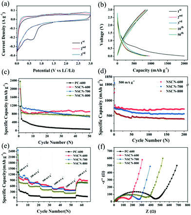
The electrochemical performance of the NSCN samples was evaluated as anode materials for LIBs. Fig. 6a shows the initial few CV curves of NSCN-600 at 0.1 mV s−1. A pronounced broad cathodic peak at around 0.60 V is observed during the first cathode sweep but it disappears in the subsequent two cycles, demonstrating the decomposition of the electrolyte and the initial formation of a solid–electrolyte interface (SEI) layer on the electrode.19 This is responsible for the irreversible loss of a number of Li+ storage sites within the carbon structure.15 The almost overlapped CV curves after the first cycle indicate the excellent reversibility of the Li+ intercalation process. As can be seen from Fig. 6b, the galvanostatic discharge/charge profiles show that the charge and discharge capacity of NSCN-600 at the first cycle is 905 and 2002 mA h g−1, respectively, corresponding to a Coulombic Efficiency (CE) of only 45.2%. A sudden decrease of discharge capacity in the second cycle primarily comes from the formation of a SEI layer on the electrode and the side reactions of an organic electrolyte. It is noteworthy that either charge or discharge profiles overlap well in the following cycles, implying the excellent cycling stability during the lithiation/delithiation process. This is supported by the cycle life shown in Fig. 6c. At a current density of 100 mA g−1, the specific discharge capacity of NSCN-600 has a slight increase from the 10th cycle. After 50 cycles, the discharge capacity is 910 mA h g−1, much higher than the theoretical capacity of graphite (372 mA h g−1) and many other reported carbon materials (Table S1, ESI†). This sharp increase may be derived from the unique porous structure of the sandwich-like NSCN-600, coinciding with the results in previous reports.66,67 In contrast, the sandwich-like NSCN-700 and NSCN-800 also exhibit a higher initial specific discharge capacity of 2357 and 2364 mA h g−1 at a current density of 100 mA g−1. However, a gradual decrease of discharge capacity in subsequent long-term cycles is observed for both samples. Finally the discharge capacity of 665 and 715 mA h g−1 is obtained for NSCN-700 and NSCN-800 at the 50th cycle. This could be ascribed to the inappropriate proportion of the micropore to the mesopore (12.16 for NSCN-700 and 1.07 for NSCN-800) and/or to the limited heteroatom content.NSCN-600 also exhibits excellent high rate capability. At a higher current density of 500 mA g−1, a high specific capacity of 719 mA h g−1 is achieved after 200 discharge/charge cycles (Fig. 6d), which is much higher than that of NSCN-700 and NSCN-800 (565 and 397 mA h g−1). When the current density is increased to 2000 mA g−1, the discharge capacity is 390, 368, and 235 mA h g−1 for NSCN-600, NSCN-700, and NSCN-800, respectively (Fig. 6e). Impressively, after the current density returns back from 2000 to 100 mA g−1, a specific discharge capacity of about 902 mA h g−1 is recovered for NSCN-600, which is higher than that of NSCN-700 (767 mA h g−1). By contrast, PC-600 exhibits much lower discharge capacity at various current densities.
As shown in Fig. 6f, EIS was performed to investigate the charge transfer at the electrode/electrolyte interface. In the high- and middle-frequency region, a compressed semicircle representing the charge transfer resistance on the electrode/electrolyte interface68 is shown in each curve. The semicircle of NSCN-600 is much smaller than that of other samples, indicating that NSCN-600 provides abundant high-speed charge-transfer channels at the electrode/electrolyte interface. The sandwich-like carbon structure with a highly porous structure can effectively improve the structural stability and decrease the agglomeration, and thus leads to fast Li+ transport and sufficient electrode/electrolyte interface, thereby promoting rapid charge transfer. In addition, it is believed that a high-level nitrogen and oxygen-doping in NSCN-600 can further enhance the electronic conductivity and electrochemical reactivity. Furthermore, the designed sandwich-like carbon nanosheets containing a nitrogen-enriched porous structure can improve the durability and electrochemical performance of the electrode in LIBs.
Conclusions
In this work, sandwich-like carbon nanosheets containing a nitrogen-enriched porous structure have been successfully prepared from glucose and guanine by a facile, economical and effective HTC method followed by KOH activation. When assembled into an anode for LIBs, NSCN-600 with a sandwich-like nanostructure shows high lithium storage capacity (910 mA h g−1 at the 50th cycle at a current density of 100 mA g−1), excellent cycling stability (719 mA h g−1 at a current density of 500 mA g−1) and superior rate capability (discharge capacity of 390 mA h g−1 at a current density of 2000 mA g−1). The outstanding electrochemical properties of NSCN-600 can be attributed to the novel sandwich-like nanostructure, appropriate portion of micropore and mesopore and high nitrogen content of pyridinic N and pyrrolic-N (9.3 wt%) in the carbon matrix. Thus, NSCN-600 is considered to be a promising alternative to graphite with great potential in high-performance LIBs. Furthermore, this sandwich-like carbon material with a hierarchical pore structure and high doping nitrogen content could also be applicable for catalysis, supercapacitors, and other fields.Conflicts of interest
There are no conflicts to declare.Acknowledgements
This research was financially supported by the NSFC (51461010, 51361006, 51401059, 51361005, 51371060, U1501242, and 51461011) and the Innovation Project of GUET Graduate Education (2017YJCX114).References
- M. M. Thackeray, C. Wolverton and E. D. Isaacs, Energy Environ. Sci., 2012, 5, 7854–7863 CAS.
- E. Yoo, J. Kim, E. Hosono, H. S. Zhou, T. Kudo and I. Honma, Nano Lett., 2008, 8, 2277–2282 CrossRef CAS PubMed.
- J. M. Kim, V. Guccini, K. Seong, J. Oh, G. Salazar-Alvarez and Y. Piao, Carbon, 2017, 118, 8–17 CrossRef CAS.
- H. Wang and H. Dai, Chem. Soc. Rev., 2013, 42, 3088–3113 RSC.
- V. Etacheri, R. Marom, E. Ran, G. Salitra and D. Aurbach, Energy Environ. Sci., 2011, 4, 3243–3262 CAS.
- S. Boukhalfa, K. Evanoff and G. Yushin, Energy Environ. Sci., 2012, 5, 6872–6879 CAS.
- H. Zhang, G. Zhang, Z. Li, K. Qu, L. Wang, W. Zeng, Q. Zhang and H. Duan, J. Mater. Chem. A, 2016, 4, 10585–10592 CAS.
- X. Zhou, Z. Dai, S. Liu, J. Bao and Y. G. Guo, Adv. Mater., 2014, 26, 3943–3949 CrossRef CAS PubMed.
- L. Shi, W. Wang, A. Wang, K. Yuan, Z. Jin and Y. Yang, J. Power Sources, 2016, 318, 184–191 CrossRef CAS.
- L. Zhao, Y. S. Hu, H. Li, Z. Wang and L. Chen, Adv. Mater., 2011, 23, 1385–1388 CrossRef CAS PubMed.
- C. Xiao, N. Du, X. Shi, H. Zhang and D. Yang, J. Mater. Chem. A, 2014, 2, 20494–20499 CAS.
- G. Wu, C. Shao, S. Qiu, H. Chu, Y. Zou, C. Xiang, H. Zhang, F. Xu and L. Sun, ChemistrySelect, 2017, 2, 10076–10081 CrossRef CAS.
- K. Jost, C. R. Perez, J. K. Mcdonough, V. Presser, H. Min, G. Dion and Y. Gogotsi, Energy Environ. Sci., 2011, 4, 5060–5067 CAS.
- Z. Xie, Z. He, X. Feng, W. Xu, X. Cui, J. Zhang, C. Yan, M. A. Carreon, Z. Liu and Y. Wang, ACS Appl. Mater. Interfaces, 2016, 8, 10324–10333 CAS.
- Z. Li, Z. Xu, X. Tan, H. Wang, C. M. B. Holt, T. Stephenson, B. C. Olsen and D. Mitlin, Energy Environ. Sci., 2013, 6, 871–878 CAS.
- B. Lee, T. Liu, S. K. Kim, H. Chang, K. Eom, L. Xie, S. Chen, H. D. Jang and S. W. Lee, Carbon, 2017, 119, 438–445 CrossRef CAS.
- C. Hu, L. Wang, Y. Zhao, M. Ye, Q. Chen, Z. Feng and L. Qu, Nanoscale, 2014, 6, 8002–8009 RSC.
- Y. Li, Z. Li and P. K. Shen, Adv. Mater., 2013, 25, 2474–2480 CrossRef CAS PubMed.
- L. Qie, W. M. Chen, Z. H. Wang, Q. G. Shao, X. Li, L. X. Yuan, X. L. Hu, W. X. Zhang and Y. H. Huang, Adv. Mater., 2012, 24, 2047–2050 CrossRef PubMed.
- Y. Chen, X. Li, K. Park, J. Song, J. Hong, L. Zhou, Y. W. Mai, H. Huang and J. B. Goodenough, J. Am. Chem. Soc., 2013, 135, 16280–16283 CrossRef CAS PubMed.
- X. Gu, C. Tong, S. Rehman, L. Liu, Y. Hou and S. Zhang, ACS Appl. Mater. Interfaces, 2016, 8, 15991–16001 CAS.
- Z. S. Wu, W. Ren, L. Xu, F. Li and H. M. Cheng, ACS Nano, 2011, 5, 5463–5471 CrossRef CAS PubMed.
- J. P. Paraknowitsch and A. Thomas, Energy Environ. Sci., 2013, 6, 2839–2855 CAS.
- Y. Mao, H. Duan, B. Xu, L. Zhang, Y. Hu, C. Zhao, Z. Wang, L. Chen and Y. Yang, Energy Environ. Sci., 2012, 5, 7950–7955 CAS.
- Z. Guan, H. Liu, B. Xu, X. Hao, Z. Wang and L. Chen, J. Mater. Chem. A, 2015, 3, 7849–7854 CAS.
- W. H. Shin, H. M. Jeong, B. G. Kim, J. K. Kang and J. W. Choi, Nano Lett., 2012, 12, 2283–2288 CrossRef CAS PubMed.
- F. D. Han, Y. J. Bai, R. Liu, B. Yao, Y. X. Qi, N. Lun and J. X. Zhang, Adv. Energy Mater., 2011, 1, 798–801 CrossRef CAS.
- C. Li, X. Yin, L. Chen, Q. Li and T. Wang, J. Phys. Chem. C, 2009, 113, 13438–13442 CAS.
- J. Deng, M. Li and Y. Wang, Green Chem., 2016, 18, 4824–4854 RSC.
- J. Ou, Y. Zhang, L. Chen, Q. Zhao, Y. Meng, Y. Guo and D. Xiao, J. Mater. Chem. A, 2015, 3, 6534–6541 CAS.
- H. Wang, T. Abe, S. Maruyama, Y. Iriyama, Z. Ogumi and K. Yoshikawa, Adv. Mater., 2010, 17, 2857–2860 CrossRef.
- N. Liu, L. Yin, C. Wang, L. Zhang, N. Lun, D. Xiang, Y. Qi and R. Gao, Carbon, 2010, 48, 3579–3591 CrossRef CAS.
- M. M. Titirici and M. Antonietti, Chem. Soc. Rev., 2010, 39, 103–116 RSC.
- Z. Gao, Y. Zhang, N. Song and X. Li, Mater. Res. Lett., 2016, 5, 69–88 CrossRef.
- L. Yu, N. Brun, K. Sakaushi, J. Eckert and M. M. Titirici, Carbon, 2013, 61, 245–253 CrossRef CAS.
- C. Falco, J. M. Sieben, N. Brun, M. Sevilla, T. van der Mauelen, E. Morallón, D. zorla-Amorós and M. M. Titirici, ChemSusChem, 2013, 6, 374–382 CrossRef CAS PubMed.
- R. Demircakan, N. Baccile, M. Antonietti and M. M. Titirici, Chem. Mater., 2009, 21, 484–490 CrossRef CAS.
- M. M. Titirici, M. Antonietti and N. Baccile, Green Chem., 2008, 10, 1204–1212 RSC.
- M. Sevilla and A. B. Fuerte, Chem. – Eur. J., 2009, 15, 4195–4203 CrossRef CAS PubMed.
- C. Falco, N. Baccile and M. M. Titirici, Green Chem., 2011, 13, 3273–3281 RSC.
- F. L. Braghiroli, V. Fierro, M. T. Izquierdo, J. Parmentier, A. Pizzi and A. Celzard, Carbon, 2012, 50, 5411–5420 CrossRef CAS.
- P. Ramakrishnan, S. Baek, Y. Park and J. H. Kim, Carbon, 2017, 115, 249–260 CrossRef CAS.
- L. Yu, C. Falco, J. Weber, R. J. White, J. Y. Howe and M. M. Titirici, Langmuir, 2012, 28, 12373–12383 CrossRef CAS PubMed.
- P. Makowski, C. R. Demir, M. Antonietti, F. Goettmann and M. M. Titirici, Chem. Commun., 2008, 39, 999–1001 RSC.
- J. Zhang, Z. Yang, J. Qiu and H. Lee, J. Mater. Chem. A, 2016, 4, 5802–5809 CAS.
- B. Wang, J. Qiu, H. Feng, E. Sakai and T. Komiyama, Electrochim. Acta, 2016, 190, 229–239 CrossRef CAS.
- H. Chen, M. Zhou, Z. Wang, S. Zhao and S. Guan, Electrochim. Acta, 2014, 148, 187–194 CrossRef CAS.
- J. Zhu, J. Yang, R. Miao, Z. Yao, X. Zhuang and X. Feng, J. Mater. Chem. A, 2016, 4, 2286–2292 CAS.
- Z. Wang, L. Sun, F. Xu, X. Peng, Y. Zou, H. Chu, L. Ouyang and M. Zhu, RSC Adv., 2015, 6, 1422–1427 RSC.
- Y. Liang, L. Cai, L. Chen, X. Lin, R. Fu, M. Zhang and D. Wu, Nanoscale, 2015, 7, 3971–3975 RSC.
- C. Zhang, S. Lin, J. Peng, Y. Hong, Z. Wang and X. Jin, RSC Adv., 2017, 7, 6486–6491 RSC.
- C. Shao, Z. Wang, E. Wang, S. Qiu, H. Chu, Y. Zou, C. Xiang, F. Xu and L. Sun, New J. Chem., 2017, 41, 12901–12909 RSC.
- L. Fan and B. Lu, Small, 2016, 12, 2783–2791 CrossRef CAS PubMed.
- C. Jin, W. Zhang, Z. Zhuang, J. Wang, H. Huang, Y. Gan, Y. Xia, C. Liang, J. Zhang and X. Tao, J. Mater. Chem. A, 2016, 5, 632–640 Search PubMed.
- H. Liu, M. Jia, B. Cao, R. Chen, X. Lv, R. Tang, F. Wu and B. Xu, J. Power Sources, 2016, 319, 195–201 CrossRef CAS.
- D. Lozano-Castelló, J. M. Calo, D. Cazorla-Amorós and A. Linares-Solano, Carbon, 2007, 45, 2529–2536 CrossRef.
- E. Raymundo-Piñero, P. Azaïs, T. Cacciaguerra, D. Cazorla-Amorós, A. Linares-Solano and F. Béguin, Carbon, 2005, 43, 786–795 CrossRef.
- Y. Gong, D. Li, C. Luo, Q. Fu and C. Pan, Green Chem., 2017, 19, 4132–4140 RSC.
- W. Guo, X. Li, J. Xu, H. K. Liu, J. Ma and S. X. Dou, Electrochim. Acta, 2016, 188, 414–420 CrossRef CAS.
- J. Yu, M. Guo, F. Muhammad, A. Wang, G. Yu, H. Ma and G. Zhu, Microporous Mesoporous Mater., 2014, 190, 117–127 CrossRef CAS.
- A. C. Ferrari and J. Robertson, Phys. Rev. B: Condens. Matter, 2001, 64, 75414 CrossRef.
- B. Li, F. Dai, Q. Xiao, L. Yang, J. Shen, C. Zhang and M. Cai, Energy Environ. Sci., 2016, 9, 102–106 CAS.
- Z. Wang, L. Sun, F. Xu, H. Zhou, X. Peng, D. Sun, J. Wang and Y. Du, Int. J. Hydrogen Energy, 2016, 41, 8489–8497 CrossRef CAS.
- D. Cai, S. Wang, P. Lian, X. Zhu, D. Li, W. Yang and H. Wang, Electrochim. Acta, 2013, 90, 492–497 CrossRef CAS.
- S. Hou, X. Cai, H. Wu, X. Yu, M. Peng, K. Yan and D. Zou, Energy Environ. Sci., 2013, 6, 3356–3362 CAS.
- Y. Zhong, X. Zhou, X. Li, S. Zhang, Y. Liu, X. Yu, H. Wang, Q. Li, Y. Fang and J. Li, Solid State Sci., 2016, 57, 16–23 CrossRef CAS.
- J. Liu, P. Lu, S. Liang, J. Liu, W. Wang, M. Lei, S. Tang and Q. Yang, Nano Energy, 2015, 12, 709–724 CrossRef CAS.
- R. Ruffo, S. S. Hong, C. K. Chan, R. A. Huggins and Y. Cui, J. Phys. Chem. C, 2009, 113, 11390–11398 CAS.
Footnote |
| † Electronic supplementary information (ESI) available: SEM images of NSCN-600, NSCN-700, NSCN-800, CS and PC-600; C 1s XPS of NSCN-600, NSCN-700 and NSCN-800. See DOI: 10.1039/c7qi00567a |
| This journal is © the Partner Organisations 2018 |

